Installing a contactless ignition system on Izh Jupiter-5 is a fairly current topic. When setting up a BSZ on Izh Jupiter-5 BSZ, it is necessary to take into account a number of nuances that can significantly affect the operation of the equipment used.
What advantages open up to users who decide to install electronic ignition on the Izh Jupiter are described below.
Most modern motorcycles are not equipped with cams, that is, breakers. Why did the manufacturer consider them unnecessary for currently sold models? The answer is quite simple. This system is not very reliable.
Many parts used in the system are sources of trouble. The most common ones are listed below:
- The ignition gaps change their original position while driving a few days after adjustment;
- A spark occurs every once in a while, since the contacts regularly burn out;
- Capacitors are constantly damaged;
- Low spark power;
- If you add two or three volts to the battery, it is quite difficult to start it. Such ignition is the reason for constant repairs while driving.
Many people mistakenly believe that it is very difficult to implement BSZ Sovek on Izh Jupiter 5. As a rule, it takes more time to purchase the necessary spare parts than to install the BSZ on Izh. Of course, after implantation, performance changes significantly in the best direction.
This is noticeable at idle. The speed of their passage has noticeably increased and the unnatural twitching has disappeared. The characteristic knocking sounds of iron components in the crankcase and accompanying detonations also disappeared. The handling of the Jupiter 5 motorcycle will improve simultaneously with the time it takes to gain speed.
Required Parts
In order for the ignition system to work correctly, a number of auxiliary parts are required. They are listed below:
- Switch for BSZ VAZ cars. You should not choose exclusively from the low price segment. The Astro switch has a lot of positive reviews;
- Hall Sensor. The best option for Jupiter 5 is a similar manufacturer VAZ. By purchasing it in branded packaging, you protect yourself from counterfeits;
- Ignition coil with two terminals. You should choose between the gazelle engine number 406 or Oka with an electronic ignition system;
- A pair of silicone armor wires with rubber caps;
- The modulator is a butterfly-shaped plate made of iron.
Modulator
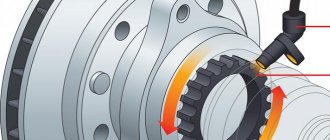
The most difficult stage is the production of the modulator. It is important to maintain the required shape. The more accurately the required dimensions are observed, the lower the likelihood of problems occurring after the system is implemented, that is, there will be no need to adjust it with a file. The ignition timing must match on any cylinder used.
The bolt hole must be located in the middle. Otherwise, the engine operation will not be synchronized. It is also recommended to check the integrity of the crankshaft bearings. If you find defects, you should immediately replace it.
The contact ignition is not able to work normally if the bearings are damaged. The thickness of the part should not exceed one and a half millimeters. If it is thin, it will not be possible to avoid deformation, and if it is thick, it will come into contact with the surface of the hall sensor housing.
To create the plate, it is allowed to use any material except steel. Aluminum and others should not be used as they are not magnetic. The drawing that must be followed can be found in the public domain. The presented diagram will be useful to those people who decide to modernize the vehicle ignition device. Below are methods for installing electrical ignition devices in Jupiter.
It must be turned by a professional turner. He will make a simple disk and draw on it the markings of elementary distances between the corners. Then, in accordance with it, you will cut out the necessary sectors at home. The cost of the modulator is seventy rubles.
It is not advisable to use an ordinary plate, since its width is less than twelve millimeters. This will not be enough to fully accumulate the energy resource in the coil. Of course, it can be installed, but achieving four thousand revolutions per minute will become impossible.
In addition to the above you will need:
- A stud with an applied thread of seven millimeters, pitch 1, as well as a pair of nuts with washers of the corresponding parameters.
The priority material for these components is brass. This is explained by the least magnetization of the plate from the generator rotor. If you use a standard bolt, then difficulties may arise with the implementation of the ignition. The bolt tends to follow the modulator as it is tightened. However, it is necessary to observe the leading indicator, maintain the same position of the rotor and modulator, and tighten the bolt. It is advisable to use a pin, since many are not able to perform all the necessary actions in total; - A set of wires with connectors for ignition without contact from VAZ. This part can be purchased or made with your own hands.
Goodbye contacts, hello BSZ!
So about the sore point. It’s no secret that it’s the 21st century, and we still make full use of the technologies of the last century. The contact ignition system is a rudiment (https://ru.wiktionary.org/wiki/rudiment) of the Izh motorcycle, that is, an underdeveloped residual organ. Advanced users get rid of the contact ignition system, replacing it with a contactless (microprocessor) one, and forget about the vagaries of the motorcycle as if it were a bad dream. What is so good about this microprocessor ignition system? From user reviews, it was found that this ignition system is unpretentious, resistant to temperature and voltage changes, not afraid of water, reliable operation at minimum engine speeds. Easy to maintain, availability of spare parts. Minimum current consumption from the power supply system. Easy to install on a motorcycle. Everything can be done at home. And these are not all the advantages of this device. It’s difficult to name the cons.
What is needed to install BSZ on an IZH Jupiter motorcycle instead of contact ignition?
1) Switch BSZ VAZ, the company does not matter.
2) Braid BSZ 2101-07 popularly used as a commutator bundle
3) Ignition coil with two outputs (Gazelle, Volga, OKA)
4) Hall sensor VAZ, the model does not matter.
5) Platform for Hall sensor
Let's move on to replacement.
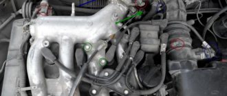
We completely dismantle the old completely unnecessary contact ignition system. We install a new ignition coil, switch, lay the BSZ braid, connect it to the on-board network according to the diagram below. The rest of the work will be lathe; it is necessary to grind out a platform for the hall sensor. I used 1.5mm thick aluminum sheet. The modulator, also known as the breaker, was machined out of 1mm metal. according to the drawing. The principle of operation is simple, the modulator passes through the slot of the Hall sensor, thereby interrupting the magnetic field in it, when the field resumes, a pulse passes through the switch, this is the moment of sparking. To make it easier to install the ignition, you can use an instant diagnostic device (MD-1), it is sold in car dealerships and plugs into the switch connector. The top dead center is set, using a device for setting the ignition timing, we move the piston 2-2.8 mm back (you can use a regular caliper with a depth gauge), then we set the modulator to break, if set with MD-1, then the moment the LED ignites. If the modulator is made symmetrically, then installing the ignition on the second cylinder is not required. If everything is done correctly and there is no spark, swap the generator brushes. On my own behalf, I will say that the system has earned beyond all praise. The video below shows a side effect of such ignition; the engine can also work in the opposite direction.
Attached videos:
System assembly and installation
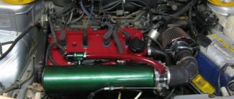
The contacts in the breaker, the capacitor, the ignition bobbins and the armor wires, which are part of the previous ignition device, are probably eliminated. The switch should be installed in the glove compartment on the right, and the ignition coil directly under the tank. There are no gaps for fastening on the reel, which means it can be attached using a thick layer of adhesive tape. The standard bolt is also eliminated along with other parts.
In place of the bolt, install a pin of the specified size and put on a washer. Then, the rotor is tightened with a nut located at its end. The hall sensor is attached to the stator by any means. The basic rule when installing it is to set the optimal cross-sectional distance of the modulator and the ratio of the radius and line of symmetry.
When the hall sensor can be secured, we apply the modulator. It should fit into the hole made in the sensor. In most situations, there is a discrepancy between the sizes, so it is necessary to place washers on the stud. If you manage to maintain the required gap, it is recommended to install an engraver and tighten the modulator with a third-party nut.
Step-by-step instructions for installing and adjusting the ignition
To carry out the option, you need to prepare a special tool, a tester, and a light bulb with 2 wires. A caliper is useful as a depth gauge. To set the gap, it is convenient to use a special feeler gauge.
Setting up SZ on IZ Jupiter 5 consists of the following steps:
- First open the generator cover.
- To make it more convenient to work, remove the right cover from the crankcase.
- Using the generator bolt, turn the crankshaft clockwise. It is necessary to ensure that the breaker contacts open to the greatest distance.
- Unscrew the screw a little and turn the eccentric. Between the contacts you need to set a gap equal to 0.4-0.6 mm. Then tighten the screw perfectly.
- Rotate the crankshaft in the direction of the clock hand. The piston should be installed at TDC.
- It is necessary to turn the crankshaft in the opposite direction, in other words, counterclockwise. At the same time, the piston should not reach TDC; a distance of approximately 3.0-3.5 mm should remain. By loosening the screws, you should establish the beginning of the contact closure. After this fact, the screws must be tightened tightly.
- To determine if the contacts are open, use a test light with wires. One wire must be connected to the breaker hammer terminal, and the other to ground. After turning on the ignition, when the contacts are closed, the light should light up.
- If BSZ is installed on IZ Jupiter
, then there is no need to set the gap.
To determine the moment you need to use a tester. The device should be set to measure voltage. The probes must be connected to the 2nd and 3rd contacts of the DC. While the modulator is not in the DC, the voltage reading on the tester should be 7 V. Just when the modulator is in the DC, the voltage reading should be between 7 and 0 V. Under such circumstances, a spark appears. - The function must be performed on each cylinder. It is better to start adjusting the gap on the left breaker. When the left breaker is adjusted, you can move to the right one.
Final actions
You should put rubber caps on the armor wires, and insert the latter into the candlesticks or coil above. If you skip this step, the motorcycle will stall when riding in rainy weather, as moisture will get into the battery.
By inserting spark plugs into the tip, it will be possible to maintain excellent contact between the battery and the volume of the vehicle. Now you will need a pre-purchased set of wires. The switch, coil and hall sensor are connected by wiring. She needs to be isolated. Of the entire mass, only a common plus is required.
Setting the appropriate options
Setting up the BSZ on Izh Jupiter 5 also requires special attention. The ignition is turned on with the tachometer connected. After thirty seconds, indicators of 3000, 4000, 5000 rpm should appear on the device panel. If they are present, then the switch is working correctly.
In other cases, you should pay attention to previously grounded candles. We insert a screwdriver into the hall connector and then pull it out. A spark should appear on the spark plugs. If it was not possible to cause a spark using the steps described above, then the reason for the incorrect operation is incorrect connections.
The setup looks like this. The dial indicator is unscrewed and the cylinder piston is adjusted. Having connected the voltmeter to the second and third connectors, you need to start rotating the modulator axis. After a jump from 7 to 0.1 volts is detected, the modulator must be secured with a nut. Usually the required advance angle is set.
The test run should be successful if you install the components yourself according to the instructions. Now you can use BSZ.
BSZ how to install on Izh Jupiter 5 Of the entire mass of useful alterations and improvements, contactless electronic ignition will bring the greatest benefit. The point is not at all in a powerful spark, but in ensuring that the mixture ignites on time. As you know, the main bearings on the Jupiter crankshaft axle shaft are put on by hand and without the slightest effort. Among other things, the bearing itself often has a play of the order of several hundredths of a millimeter. Add to this company of unfavorable circumstances a large breaker cam console, add up all these backlashes and radial runouts. Get a nightmare! After some 10,000 km, the spread of ignition timing due to crankshaft chatter will be about 4 mm from the set value. What kind of precise engine operation can we talk about here? In a non-contact system, due to the absence of a mechanical connection between the rotor and the sensor, the play of the crankshaft axle shaft has virtually no effect on the moment the spark appears. Engines improved in this way became faster throughout the entire speed range, and the nature of their operation was softer - thanks to the synchronized ignition of the mixture in both cylinders and the absence of detonation. By the way, running the engine without detonation significantly increases its service life. I installed the BSZ on my Jupiter, although I tinkered with the installation, but it was worth it. I forgot what a misfiring ignition is in general (it’s not even afraid of dampness!), the engine began to run much smoother, softer, the dynamics improved, at speed the engine became much more sensitive to gas, the idle speed was smoother and more stable. It starts even with a fairly weak battery with a “half kick” What we need: a). Switch for contactless electronic ignition of a front-wheel drive VAZ car. Take the switch only in its original packaging from a CAR STORE and with a warranty of at least a year. Average price 350 rub. b). Hall Sensor. Any from the same VAZ, but also in the original packaging. Price approximately 80 rubles. V). The ignition coil is two-terminal, from the Gazelle, but always from the 406 engine. You can take it from the Oka for electronic ignition, there is absolutely no difference between them. (350 rub.) d). Two silicone armored wires with rubber caps. Price from 100 rub. d). Modulator and hall sensor mount They need to be sharpened by a lathe. I don’t recommend using a regular plate as a modulator. Its width is no more than 12 mm, which is not enough to fully accumulate the energy of the coil. Of course, you can set it, but you won’t be able to see more than 4000 revolutions per minute e) We also buy instant diagnostics of MD-1 and emergency ignition of AZ-1 in a car store. Prices for these devices are around 70 rubles for each g) Wiring kit with connectors for contactless ignition VAZ price 80-100 rubles. Well, have you bought everything and are ready to collect? Let's go... The old ignition system (breaker contacts, ignition coils, capacitors, armored wires) is completely abolished. The switch is installed in the right glove compartment, the ignition coil is under the tank. Unfortunately, there are no holes or fastenings for the bracket on the coil, so I couldn’t think of anything better than to attach it to the frame with a thick layer of copper wire. We assemble the modulator and the DC mount, install everything on a standard generator, as shown in the figure: The main thing during installation is to maintain the diameter of the modulator (the gap between the lower partition of the hall sensor and the modulator should be 1-1.5 mm) and the alignment of the mount (the radius of the modulator should pass along the axis of symmetry hall sensor). I also screwed the sensor connector to the side of the generator. After installing the hall sensor, put on the modulator and see if it fits into the sensor slot. If not (and this is 90%), then we place spacer washers on the stud. After the required gap has been maintained, we install the grower and tighten the modulator with the standard bolt of the generator. Next steps: We put rubber caps on the armor wires, and insert the armor wires themselves (they should have special copper tips) into the candlesticks and into the coil. We pull the above-mentioned caps on top. If you don’t do this, you’ll be pushing the motorcycle on foot when riding in the rain. We immediately insert the spark plugs into the tips and ensure reliable contact with the “ground” of the motorcycle. Using wiring, we simply connect the switch, hall sensor, coil and AZ-1 with wires. (AZ will have to be soldered and a switch button attached to its 1st connector so that the constant spark turns on at our discretion). Moreover, we “pack” the wires into a PVC tube or simply wrap them with electrical tape. Of the entire purchased heap, we will need to display only the general “plus” of the system on the “panel”. We “lead” it to the right “Move-Stop” switch, having previously unsoldered the standard wires from it. We connect the second wire from the switch to terminal “1” of the ignition switch (the second wire from the same terminal goes to the signal). Here is the actual connection diagram: Here: 1 battery 2 ignition switch 3 spark plugs 4 ignition coil 5 AZ 6 switch 7 Hall sensor Well, everything seems to be assembled, you can configure it. Checking functionality - we throw both spark plugs onto the cylinders, take a screwdriver (you can also use a manufactured modulator), insert it into the slot of the hall sensor and pull it out. At this moment there should be a spark (on both spark plugs). If after the above steps there is still no spark, check the correct connections. I assure you that when using “not left-handed” components, everything should work as it should. Now the setup. Adjust the piston of one of the cylinders to TDC, move it back 2.8 mm (when using AI-92 gasoline, it is advisable to reduce the angle to 2.5 mm). Next, connect the MD -1 instead of the switch and begin to slowly twist the DC mount around the modulator (clockwise). As soon as you “catch” that the “D” indicator lights up on the instant diagnostics, fix the DC mount in this position. Well, what can I say, screw in the spark plugs, put them on spark plugs, reconnect the switch, pump up the gasoline... Drin-dyn-dyn... Soft rustling of the engine, no detonation, idle 500 rpm and excellent battery charging... Now you have a BSZ. And when you turn on the AZ button, you can now start the motorcycle even without a kick starter, although riding in AZ mode (constant spark) is recommended only if the DH fails and at a speed of no more than 90 km/h
Many owners of Izhmash equipment set the ignition themselves. This process is not difficult if you understand the structure of the system and the principle of operation. The article gives instructions on how to do it on a motorcycle, including the IZH Jupiter 5.
Making ignition elements for IZH Jupiter 5 with your own hands
You can manufacture individual elements and make electronic ignition for Izh Jupiter 5 with your own hands. To do this, you will need to make your own modulator. The quality of its manufacture determines the reliability of the entire plant.
The modulator is made perfectly symmetrical. A fixed curtain should cover 30 degrees of the area when it is rotated. Once again, it must be emphasized that the modulator is the determining element in the motorcycle ignition system. The smooth operation of the engine is determined by this small device. If the modulator is properly manufactured, then its shutter should not, in the open state, block the magnet and magnetic circuit of the Hall sensor.
The closed state must ensure their simultaneous closure for the passage of magnetic flux. The switch must receive clear pulses of a certain size from the Hall sensor; ensuring this condition is the task of the modulator.
In what cases is ignition adjustment necessary?
During the operation of the vehicle, the owner faces many problems. The most serious failure is related to the engine. In order to spend significant funds on major repairs, it is necessary to monitor the technical condition of the motorcycle and carry out preventive work, including adjusting the valves and valves (video author - Hana Rulyu).
If you do not monitor the SZ, then the motorcycle engine may not reveal its full potential and will not work at full capacity. This can lead to a reduction in its service life. An ignition adjustment is necessary if the engine is running poorly, the muffler or carburetor is firing. True, before setting up the SZ, you should make sure that the cause of the malfunction is in it.
It happens that the flywheel bolt, which connects the two halves of the crankshaft, comes loose, begins to play and does not work well. Sometimes he even cuts the key.
Setting up the SZ may be necessary after repairing lock 5. The installation and connection itself are carried out according to the diagram.