The generator stator contains a three-phase winding made in a star configuration (the terminals of the phase windings have a common point). The second ends of the phase windings are connected to a rectifier bridge consisting of six silicon diodes (valves) - three “positive” and three “negative”. The valves are pressed into two horseshoe-shaped aluminum holder plates in accordance with the polarity (positive and negative - on different plates); one of the plates also contains three additional diodes, through which the excitation winding of the generator is powered after starting the engine. The plates are combined into a rectifier unit mounted on the back cover of the generator (under a plastic casing).
The excitation winding is located on the rotor of the VAZ 2110 generator, its leads are soldered to two copper slip rings on the rotor shaft. Power is supplied to the field winding through two carbon brushes. The brush holder is structurally combined with the voltage regulator and is mounted on the back cover of the generator.
The VAZ 2110 voltage regulator is non-separable; if it fails, it is replaced.
To protect the on-board network from voltage surges during operation of the ignition system and reduce interference with radio reception, a capacitor with a capacity of 2.2 μF (±20%) is connected between the terminals of the “positive” and “negative” valves (between the “+” and “ground” of the generator) on the rectifier block.
When the ignition is turned on, voltage is supplied to the generator excitation winding (terminals “D” of the generator and “D+” of the regulator) through the warning lamp in the instrument cluster (the lamp is lit). After starting the engine, the excitation winding is powered by additional diodes of the rectifier unit (the control lamp goes out). If the lamp lights up after starting the engine, this indicates a malfunction of the generator or its circuits.
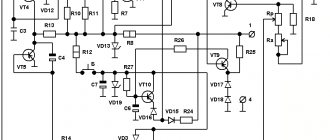
Connection diagram for generator VAZ 2110 94.3701
Electrical diagram of the VAZ 2110 generator: 1 - battery, 2 - generator, 3 - relay and fuse block (mounting block), 4 - ignition switch, 5 - instrument cluster, 6 - battery discharge warning lamp (installed from 1997 until In 1997, an electronic voltmeter with an LED was installed).
Diagnostics of the VAZ 2110 generator
Start the engine, let it run for a few minutes, then, pressing the gas pedal, bring the crankshaft speed to 3000 rpm. Turn on all consumers: high beam headlights, heated rear window, heater fan, windshield wiper, hazard warning lights. Measure the voltage at the battery terminals, which should be above 13 V. If this is not the case, the generator windings are faulty (open or short), the voltage regulator with the brush assembly, or the contact rings of the field winding are oxidized. In order to make sure that the VAZ 2110 voltage regulator is working properly, turn off all consumers except the high beam headlights and measure the voltage again. It should be within 13.2-14.7 V. The removed voltage regulator can be checked by connecting a lamp (1-5 W, 12 V) between the brushes, and a power source (DC only) to the “D+” and “ground” terminals current!), first with a voltage of 12 V, and then 15-16 V. In the first case, the lamp should light, in the second - not. If the lamp lights up in both cases, there is a breakdown in the regulator; if it doesn’t light up, there is a break or broken contact between the brushes and the regulator terminals. In both cases the regulator should be replaced. To check the valves of the VAZ 2110 rectifier unit, disconnect the wires from the battery, generator and from the “D+” terminal of the voltage regulator. Connect the “plus” of the battery through a lamp (1-5 W, 12 V) to the “B+” terminal of the generator, and the “minus” to its body. If the lamp is on, then there is a short circuit in both the block of “positive” and the block of “negative” valves. To check the short circuit in the “positive” valves, connect the “+” battery through a lamp to the “B+” terminal of the generator, and “-” to the terminal of one of the phase windings of the stator. If the lamp is on, one or more positive valves are broken. To check the short circuit in the “negative” valves, connect the “+” battery through a lamp to the output of one of the phase windings of the stator, and “-” to the generator housing. If the lamp is on, one or more negative valves are broken or the stator windings are shorted to the generator housing. To prevent short-circuiting of the windings, remove the generator from the car and, having disconnected the windings from the voltage regulator and rectifier unit, check their short circuit to ground using a lamp or ohmmeter. The generator valves can also be checked with an ohmmeter without connecting the battery and test lamp. The short circuit of additional diodes can be checked by connecting the “+” batteries through a lamp to the “D” terminal of the generator, and “-” to the terminal of one of the stator phase windings. If the lamp is on, one or more additional diodes are broken. A break in the main valves is determined by a sharp decrease in the output current (voltage drop under load). However, this may also be a consequence of a break or short circuit in the generator windings. A break in the additional valves can be determined by the low voltage at plug “D” (below 14 V) at an average generator rotor speed. The serviceability of each diode (main or additional) can only be determined with a removed rectifier unit using an ohmmeter or a test lamp. If the VAZ 2110 generator rectifier unit fails, it is recommended to replace it as an assembly. It is possible to replace individual valves, but the main valves will require repressing them in the holder - an operation that requires care and skill.
VAZ 2110 generator belt, tension check
Checking the tension of the VAZ 2110 generator belt must be carried out periodically. If the tension is weak, the alternator belt may simply slip, especially during wet weather. As a result, poor belt tension can lead to insufficient battery charging. But you should not overtighten the alternator belt; this will lead to rapid wear of the belt itself or its unexpected break. In addition, when the belt is overtightened, the generator bearings are subject to additional stress and wear out quickly. Below is a schematic drawing that will help you understand how to properly tension the VAZ 2110 alternator belt.
- 1 – upper bracket of the generator
- 2 – nut
- 3 – generator adjusting bolt
- 4 – generator
- 5 – bolt for hinge mounting of the generator to the bottom bracket
- 6 – generator belt
- 7 – drive pulley on the crankshaft
To ensure normal deflection of the VAZ-2110 generator belt, which is indicated as “A” in the schematic diagram, it is necessary to loosen the generator nut “2” and the bolt nut “5”. Then, by rotating the adjusting bolt “3”, you can move the generator closer/further from the engine, thereby loosening/tensioning the generator belt. The normal deflection of belt “A” should be from 6 to 10 mm, subject to pressure on the belt with a force of 98 N or 10 kgf.
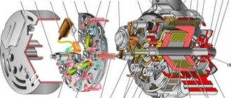
Design of the VAZ 2110 generator
A working generator should deliver from 13 to 14.5 volts to the battery terminals. If this indicator is less when the engine is running and warm, then the generator is faulty. There should be no sudden jumps when consumers are turned on. If the charge is more than 15 volts, this is just as bad; overcharging will quickly damage the battery. When overcharging, water boils away from the electrolyte and the plates crumble. The main reason for the increased charge is the failure of the voltage regulator. Below is a schematic and very detailed image of the VAZ 2110 generator
- 1 – generator pulley
- 2 – washer
- 3 – front cover
- 4 – spacer ring
- 5 – generator rotor
- 6 – generator stator
- 7 – back cover
- 8 – casing
- 9 – rectifier unit with capacitor
- 10 – brush holder with voltage regulator
Very often the voltage regulator fails; replacing it is not difficult, since it is not necessary to completely disassemble the VAZ 2110 generator. But due to the fact that the voltage regulator and current-collecting brushes are a single and non-separable part, the replacement is carried out together with the generator brushes.
Often, owners of “ten” are faced with replacing additional diodes that are located on the rectifier block, in the figure above, numbered “9”. To replace generator diodes, you must have epoxy resin and a soldering iron. Using a soldering iron, you need to carefully unsolder the damaged one and solder a new diode. And the resin is necessary for reliable gluing of the diode body. In this case, the old resin must be cleaned off.
Generator bearing replacement process
General view of the front and rear bearing of the generator
Existing play indicates that the bearing has indeed failed.
So, let's consider the step-by-step process of replacing a product with a VAZ-2112.
- We place the car on a pit or overpass. The main thing is that there is access from below.
- We dismantle the “minus terminal”.
- Remove the generator belt.
Pull the alternator belt through the slot - To further carry out the work, you will need to dismantle the generator itself.
- Disconnect the appropriate wires to the generator.
Disconnect all wires that go to the generator - Loosen the nut that holds the tension bolt.
- Remove the adjusting bolt.
Unscrew and remove the generator adjusting bolt - Remove the lower engine protection.
We dismantle the engine protection - Unscrew the 2 lower mounting bolts.
- We are dismantling the generator.
It comes out through the bottom. We unscrew the fastenings and dismantle the generator - When the generator is in your hands, you can put it on the table. Now, you can proceed directly to the repair.
- Having blocked the rotor from turning, remove the pulley.
- We dismantle the casing.
To do this, you need to pull back the latches. Block the rotor and unscrew the pulley - Remove the front and back covers.
Generator disassembly diagram - Now feel free to move on directly to replacing the bearing.
Using a hammer, knock out the rotor from the cover along with the bearing - The product can be dismantled using a special puller, or simply by knocking it out of its seat.
- Installation is carried out in reverse order.
Replacing bearings
- We clean the load-bearing elements well.
Disassembled generator - Apply sealant to the seat.
Applying sealant - We press in new bearings.
One bearing is pressed in - The most difficult part is to press in the inner bearing.
First we remove it. There is a puller, but if it is not available, then we use a regular key. Removing a bearing without using a puller - We put on a new one.
New bearing ready for use
Next, we assemble the generator and install it back!
>
What bearings are on the VAZ-2112 generator?
The choice of bearing should be taken seriously, since the stable voltage in the on-board network, as well as the wear of the generator itself, depends on this part.
Since there are 2 bearings in the unit - front and rear, each of them has its own markings and dimensions.
So, the front ones are marked - 6302 or 6303, but the rear ones - 6202 or 6203.
Generator front and rear bearings
Since there are many fakes on the automotive spare parts market, especially with regard to bearings, when choosing, you should pay special attention to the production of this product. The wear of many other generator parts will depend on the quality.
Therefore, it is recommended to check the availability of a quality certificate, as well as the presence of markings and holograms.
Original
6303-10B is the original catalog number of the generator bearing for the 10 series of Lada cars produced by AvtoVAZ. The average cost of a product is up to 150 rubles.
Analogs
Not original bearings, strip, and plug. Vologda bearings VBF
In addition to the original, you can buy a substitute product. Of course, now bearings can be selected depending on the size or number, but manufacturers of analogues still decided to produce high-quality products for cars.
| Manufacturer's name | Catalog number | Price |
| F.A.G. | 6303 | 450 |
| Nachi | 6203ZZ | 150 |
| NTN | 6203ZZ | 180 |
| Koyo | 6303C3 | 200 |
| SNR | 6203.ZZ | 400 |
There are several reasons for generator bearing failure:
>
- Wear. Like any part, the generator bearing fails during operation.
- Violation of the rules of operation and maintenance will lead to the product failure.
- External factors such as dirt, salt and road chemicals lead to the part being subject to increased wear.
- Poor quality can cause premature failure.
- Lack of lubrication.
The grease may have dried out over time. The lubricant is almost invisible
Generator bearing VAZ 2110
Another problem with the VAZ 2110 generator is the rotor bearing. More precisely, two rotor bearings, one at each end of the generator rotor shaft. The front bearing is rolled into the front cover of the generator; the entire assembly is not dismountable, so the bearing must be replaced with the entire cover assembled. The situation with the rear bearing is as follows; it is simply pressed onto the shaft. To remove it you will need a special bearing puller. It is advisable to use a vice to install a new bearing. Because the rotor shaft on which you will press the new bearing must be stationary.
Add a comment Cancel reply
You must be logged in to post a comment.
1200 rub. for the photo report
We pay for photo reports on car repairs. Earnings from 10,000 rubles/month.
Write:
The most basic function of the generator is to charge the battery and power the electrical equipment of the engine.
A generator is a mechanism that converts mechanical energy into electrical energy. The generator has a shaft on which a pulley is mounted, through which it receives rotation from the engine crankshaft.
Interactive image of the generator circuit. Works on mouseover
A car generator is used to power electrical consumers, such as the ignition system, on-board computer, car lighting, diagnostic system, and it is also possible to charge a car battery. The power of a passenger car generator is approximately 1 kW. Car generators are quite reliable in operation because they ensure uninterrupted operation of many devices in the car, and therefore the requirements for them are appropriate.
Generator device
The design of a car generator implies the presence of its own rectifier and control circuit. The generating part of the generator, using a stationary winding (stator), generates three-phase alternating current, which is then rectified by a series of six large diodes and the direct current charges the battery. Alternating current is induced by the rotating magnetic field of the winding (around the field winding or rotor). Next, the current is supplied to the electronic circuit through the brushes and slip rings.
Generator structure: 1.Nut. 2. Washer. 3.Pulley 4.Front cover. 5. Distance ring. 6.Rotor. 7.Stator. 8.Back cover. 9.Casing. 10. Gasket. 11.Protective sleeve. 12. Rectifier unit with capacitor. 13.Latch holder with voltage regulator.
The generator is located at the front of the car engine and is started using the crankshaft. The connection diagram and operating principle of a car generator are the same for any car. There are, of course, some differences, but they are usually associated with the quality of the manufactured product, the power and the layout of the components in the motor. All modern cars are equipped with alternating current generator sets, which include not only the generator itself, but also a voltage regulator. The regulator equally distributes the current in the excitation winding, and it is due to this that the power of the generator set itself fluctuates at a time when the voltage at the power output terminals remains unchanged.
The principle of operation of a car generator
Connection diagram for the VAZ 2110-2115 generator
The alternator connection diagram includes the following components:
- Battery.
- Generator.
- Fuse block.
- Ignition.
- Dashboard.
- Rectifier block and additional diodes.
The principle of operation is quite simple: when the ignition is turned on plus through the lock, the ignition goes through the fuse box, light bulb, diode bridge and goes through a resistor to minus. When the light on the dashboard lights up, then the plus goes to the generator (to the excitation winding), then during the process of starting the engine, the pulley begins to rotate, the armature also rotates, due to electromagnetic induction, electromotive force is generated and alternating current appears.
Next, the diode passes plus into the rectifier block through a sine wave into the left arm, and minus into the right arm. Additional diodes on the light bulb cut off the negatives and only positives are obtained, then it goes to the dashboard assembly, and the diode that is there allows only the negative to pass through, as a result the light goes out and the positive then goes through the resistor and goes to the negative.
The principle of operation of a car DC generator can be explained as follows: a small direct current begins to flow through the excitation winding, which is regulated by the control unit and is maintained by it at a level of slightly more than 14 V. Most generators in a car are capable of generating at least 45 amperes. The generator operates at 3000 rpm and above - if you look at the ratio of the size of the fan belts for the pulleys, it will be two or three to one in relation to the engine frequency.
Replacement process detailed instructions
We will look at options with 8- and 16-valve engines, which are present in the VAZ 2112 and 2110 models. Regardless of the number of valves, the same set of tools will be required for replacement. The list includes standard tools that can be found in almost every driver's garage.
Timing belt for VAZ 2110 16 valves
In addition to the timing belt itself and the roller for the VAZ 2110 or 2112, you will need:
- a special key that regulates the degree of tension of the roller;
- spanner set to “17”;
- key to “15”;
- key to “10”;
- installation, as an alternative - a powerful screwdriver.
Replacement on an 8-valve engine
Replacing the VAZ 2110 8 valve timing belt is as follows:
- First of all, we de-energize the battery - for this you need to get the negative wire;
- We unscrew the bolts that hold the timing belt protective casing, and then remove the casing;
- On the passenger side, it is necessary to remove the engine compartment mudguard along with the protective element and the right wheel;
- Our task is to ensure that the marks on the cover and, accordingly, on the pulley match, as indicated in all the diagrams. To do this, you need to twist the part clockwise;
- We go to the gearbox and remove the plug from it;
- We need to check the alignment of the marks in this hole;
- We block the flywheel - for this you can use a mounting tool or a powerful screwdriver;
- Now you can remove the timing generator pulley;
- We got to the nut that holds the timing belt pulley - it needs to be loosened, but not unscrewed;
- Now we have reached the required element of the VAZ 2110 or 2112 timing belt. Now it can be removed. All parts that it covered must be cleaned with detergent. After removing dirt, the area should be wiped with a clean rag;
- Next, a new timing belt and tensioner roller are installed - follow the direction indicated on the arrow. Sometimes it happens that the manufacturer does not indicate the arrows, in which case, you need to place the element so that the inscription is read from left to right;
- To tension, you need to turn the roller counterclockwise.
- The next step is to test the timing belt and its tension. You need to check the element with a cold engine, and the temperature in the garage or box should be within +15-+30C. We start the engine and inspect the timing belt.
If there are no unnecessary sounds or vibrations, then all the elements can be installed back - these are the wheel, casing and mudguard.
Replacement on a 16-valve engine
Despite the fact that there are more valves, replacing the timing belt is no more difficult than on the version with 8 valves. So, replacing the VAZ 2110 16 valve timing belt is performed as follows:
- As in the case of the VAZ 2110 or 2112, where there are 8 valves, we need to dismantle the belt protection. It is held in place by 6 bolts.
- Next, you need to remove the chip from the crankshaft sensor - unscrew the mount and take out the sensor itself. For clarity, you can study the photo.
- If you dismantle the gas distribution mechanism yourself, then you probably noticed the absence of one tooth. This is done so that the sensor can independently find the dead center. This feature can also be used to lock the crankshaft.
- Blocking can be done when a tube of a suitable size is placed in the hole under the sensor. Now the pulley is blocked, as a result, it can be safely dismantled.
- Next, the work scheme is practically no different from removing the 8-valve timing mechanism with your own hands - loosen the roller fastening and remove the faulty or worn belt.
- There are two ways to install a new element: remove the tension roller and then install the belt along with it, or do it by turning the camshaft.
- When the new element is installed, you can return everything to its original position. You should start by fastening the pulley - tighten the bolt and align the gear - the marks on the oil pump will help with this. If they are missing, then you can make a mark yourself.
- The parts must be combined carefully, since the timing gear should not get knocked out.
- Using a special wrench, we must tighten the belt. Not everyone has such a wrench, but as an alternative you can always take a powerful screwdriver and two nails. It is also worth remembering the nut, which must be tightened tightly.
- We check the tension; the rubber should move away from the gears, but there should be no folds.
- All that remains is to turn the crankshaft 2 times and make sure that the marks remain in the same place - the work is completed
Check the gas distribution mechanism every 10 thousand kilometers, and then you will not have to spend money on expensive repairs.
Generator connection diagram for VAZ 2107
The VAZ 2107 charging scheme depends on what type of generator is used. To recharge the battery on cars such as VAZ-2107, VAZ-2104, VAZ-2105, which have a carburetor engine, you will need a G-222 type generator or its equivalent with a maximum output current of 55A. In turn, VAZ-2107 cars with an injection engine use a generator 5142.3771 or its prototype, which is called a high-energy generator, with a maximum output current of 80-90A. It is also possible to install more powerful generators with an output current of up to 100A. Absolutely all types of alternating current generators have built-in rectifier units and voltage regulators; they are usually made in the same housing with brushes or are removable and mounted on the housing itself.
The VAZ 2107 charging circuit has minor differences depending on the year of manufacture of the car. The most important difference is the presence or absence of a charge indicator lamp, which is located on the instrument panel, as well as the method of connecting it and the presence or absence of a voltmeter. Such circuits are mainly used on carburetor cars, while on cars with injection engines the circuit does not change, it is identical to those cars that were manufactured previously.
Generator set designations:
- “Plus” of the power rectifier: “+”, V, 30, V+, WAT.
- “Ground”: “-”, D-, 31, B-, M, E, GRD.
- Excitation winding output: Ш, 67, DF, F, EXC, E, FLD.
- Output for connection to the serviceability lamp: D, D+, 61, L, WL, IND.
- Phase output:
,W,R,STA.
- Output of the stator winding zero point: 0, MP.
- Output of the voltage regulator for connecting it to the on-board network, usually to the “+” of the battery: B, 15, S.
- Voltage regulator output for powering it from the ignition switch: IG.
- Voltage regulator output for connecting it to the on-board computer: FR, F.
Generator circuit VAZ-2107 type 37.3701
- Accumulator battery.
- Generator.
- Voltage regulator.
- Mounting block.
- Ignition switch.
- Voltmeter.
- Battery charge indicator lamp.
When the ignition is turned on, the plus from the lock goes to fuse No. 10, and then goes to the battery charge indicator lamp relay, then goes to the contact and to the coil output. The second terminal of the coil interacts with the central terminal of the starter, where all three windings are connected. If the relay contacts close, then the control lamp lights up. When the engine starts, the generator generates current and an alternating voltage of 7V appears on the windings. Current passes through the relay coil and the armature begins to attract, and the contacts open. Generator No. 15 passes current through fuse No. 9. Similarly, the excitation winding receives power through the brush voltage generator.
Replacing the timing belt on an Accent 16 valve
The procedure is carried out on a pit or a lift. Experts recommend purchasing a kit and immediately replacing both rollers along with the belt. If this is not done, worn parts will negatively affect the newly installed belt, which will affect the service life of the latter.
Work order:
- Open the hood and remove the drive belts (alternator, power steering and air conditioning).
- Unfasten the power steering reservoir and move it so that the device does not interfere with further work.
- Remove the protective cover from the place where the timing belt is located.
- Place the socket wrench onto the bolt in the central part of the crankshaft and press it into the spar.
- Disconnect the low-voltage connectors from the coil.
- Turn the starter clockwise until the shaft bolt comes off. The mount is rotated until the crankshaft pulley marks align. Afterwards you can remove the fasteners, pulleys and plate.
- Unscrew the fasteners of the tensioner roller (to prevent the thread from breaking, the roller must be held).
- This completes the analysis - you can remove the belt and replace the idler roller.
- Place the new belt so that the marks on the shaft pulleys match the marks on the casing.
- Install the tension roller while holding the spring - you can use a long screwdriver; the required belt tension will be determined by itself due to the action of the spring.
- Tighten the tension roller adjustment bolt, then the main bolt to tension the belt.
- Position the crankshaft pulley and tighten the fastener.
- Turn the crankshaft 2 turns and check if the marks match.
- Collect all remaining parts. To tighten the crankshaft bolt, you must use a hammer or wrench - the fasteners are tightened counterclockwise!
Now you know how to change the timing belt yourself. Below are useful tips and instructions for installing and checking tags.
Important Tips:
- The procedure is carried out only on a cold engine.
- After removing the belt, turning the shafts is prohibited!
- If the replacement is carried out after 50 thousand km, the drive belts should also be replaced.
- It’s convenient to change spark plugs, oil filter and oil at the same time - this way you don’t have to disassemble and reassemble the car several times.
Timing marks Hyundai Accent 16 valves
The most problems arise with the correct placement of labels. In fact, to do everything correctly, you must first remove the lower pulley, then loosen the tensioner, dismantle the belt, set the marks and assemble the mechanism. Next, to check, you need to rotate the shafts several times and see if the marks match. As a result of the rotation of the shafts, the belt is tensioned.
Checking tags:
Remove the upper side cover and place a mark on the camshaft pulley.
What should I do if noise appears after replacement?
Sometimes after replacing the belt, noise or whistling may appear in the timing belt area. More often this sound appears when starting the engine when it is cold, and after warming up it disappears. The most likely cause of the noise is:
Wear of timing system components (if the rollers have not been replaced)
Replacing the timing belt on a 16-valve Accent is no different than replacing the timing belt on most other belt-driven passenger cars. During the work, it will be necessary to remove, and in some cases replace, three more drive belts - the generator, the air conditioner and the power steering. Also, when replacing the timing belt, it is recommended to immediately change the mechanism rollers.
Charging diagram for VAZ with injection engines
This scheme is identical to the schemes on other VAZ models. It differs from the previous ones in the method of exciting and monitoring the serviceability of the generator. It can be carried out using a special control lamp and a voltmeter on the instrument panel. Also, through the charge lamp, the generator is initially excited at the moment it starts working. During operation, the generator operates “anonymously,” that is, excitation comes directly from pin 30. When the ignition is turned on, power through fuse No. 10 goes to the charging lamp in the instrument panel. Then it goes through the mounting block to pin 61. Three additional diodes provide power to the voltage regulator, which in turn transmits it to the excitation winding of the generator. In this case, the indicator lamp will light up. It is at that moment when the generator operates on the plates of the rectifier bridge that the voltage will be much higher than that of the battery. In this case, the control lamp will not light up, because the voltage on its side on the additional diodes will be lower than on the side of the stator winding and the diodes will close. If the control lamp lights up while the generator is running, this may mean that additional diodes are broken.
Principle of operation
In order for the generator to supply current to the load, the field winding must be energized. This, in fact, happens when we turn on the ignition. Next, the crankshaft of a running engine causes the armature to rotate. At this time, electricity begins to be generated in the stator winding, which is sent to the on-board network.
In VAZ-2110 cars, the generator produces alternating current, and all consumers are designed for direct current. To convert it, a rectifying diode unit is used.
But that's not all. The fact is that the voltage produced by the generator constantly changes depending on the number of crankshaft revolutions. To stabilize it, a voltage regulator relay is used.
As a result, at the terminals of the device we have a constant electric current of stable voltage.
Checking generator operation
You can check the functionality of the generator in several ways using certain methods, for example: you can check the output current of the generator, the voltage drop on the wire that connects the current output of the generator to the battery, or check the regulated voltage.
To check, you will need a multimeter, a car battery and a lamp with soldered wires, wires for connecting between the generator and the battery, and you can also take a drill with a suitable head, since you may have to twist the rotor by the nut on the pulley.
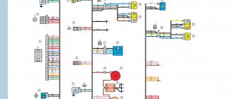
Generator system diagram
Visual diagram of generator circuit connections
1 – battery; 2 – generator; 3 – mounting block; 4 – ignition switch; 5 – battery charge indicator lamp, located in the instrument cluster
- The “minus” of the battery should always be connected to ground, and the “plus” should always be connected to the “B+” terminal of the generator. Failure to turn the battery back on will immediately cause increased current through the generator valves and they will fail.
- It is not allowed to operate the generator with the battery disconnected. This will cause short-term overvoltages to occur at the “B+” terminal of the generator, which can damage the generator voltage regulator and electronic devices in the vehicle’s on-board network.
- It is prohibited to check the functionality of the generator “for spark” even by briefly connecting the “B+” terminal of the generator to “ground”. In this case, a significant current flows through the valves, and they fail. The generator can only be checked using an ammeter and voltmeter.
- The generator valves are not allowed to be checked with a voltage of more than 12 V or with a megger, since it has a voltage too high for the valves and they will be broken during testing (a short circuit will occur).
- It is prohibited to check the vehicle's electrical wiring with a megger or a lamp powered by a voltage of more than 12 V. If such a check is necessary, you must first disconnect the wires from the generator.
- The insulation resistance of the generator stator winding with increased voltage should be checked only on a stand and always with the terminals of the phase windings disconnected from the valves.
- When electrically welding components and parts of the car body, you should disconnect the wires from all terminals of the generator and battery.
Generator type 94.3701 – alternating current, three-phase, with built-in rectifier unit and electronic voltage regulator, right rotation (drive side).
An AAK-5102 generator made in Slovenia can be installed on some vehicles. In terms of its characteristics and installation dimensions, this generator is interchangeable with the 94.3701 generator, but has some differences in the design of components and parts. This chapter describes the 94.3701 generator.
The stator and covers 10 and 11 (Fig. Generator 94.3701) are tightened with four screws. The rotor shaft 19 rotates in bearings 20 and 25, which are installed in the covers. Power is supplied to the rotor winding (excitation winding) through brushes and slip rings 27.
The three-phase alternating current induced in the stator winding is converted into direct current by a rectifier unit attached to the cover 10. The electronic voltage regulator 8 is combined into one unit with a brush holder and is also attached to the cover 10.