Lamborghini Miura
This classic supercar, designed by the talented designer Marcello Gandini, has a very elegant, almost reference appearance. Every element of the interior works for this, including door handles, which you cannot detect with the naked eye.
The fact is that they are hidden in the lower blades of the ventilation holes, and the opening button is located just above. Those. First you have to stick a couple of fingers through to press the button, and then pull the not very comfortable handle. But it's all for the sake of design!
Tesla Model X
Retractable door handles have become something of a trend these days. These can be found on the Range Rover Velar or Tesla Model 3. But with the Tesla Model X crossover, everything is a little different.
If you expect the handles to come out of the body when you approach it with the key, then this will not happen. The thing is, those shiny things aren't pens, they're just big buttons. You will have to open the doors directly at the edge (from the front) or wait until the “falcon wings” at the back rise using an electric drive.
Door latches (Freelander 2)
| Pos. | Spare part no. | Name |
| 1 | – | Internal door lock/unlock button |
| 2 | – | Internal door handle |
| 3 | – | Mechanical door lock release cable (left front door only) |
| 4 | – | Outer door lock cable |
| 5 | – | Lock retainer |
| 6 | – | Emergency mechanical door lock (only for left front door) |
| 7 | – | Door handle lock cover |
| 8 | – | External door handle |
| 9 | – | Door latch |
| 10 | – | Electrical connection to the door control module |
| 11 | – | Inner door lock cable |
Door latches are installed on the rear ends of the doors, and each of them engages with a corresponding latch on the “B” and “C” pillars. Each interior and exterior door handle is connected to its corresponding door latch via a cable. The left front door has a third cable that connects the door latch to the hidden emergency mechanical door lock.
Each door latch is a sealed assembly consisting of the following elements:
- Locking motor.
- Double locking motor (all models except North American, Japanese and Gulf Coast models).
- Door soft closing switch.
Electrical connectors in each door latch provide interface to the door control module, CJB and AJB. The front door control modules are connected to the CJB via a medium-speed CAN bus; The rear door control modules are connected via a local interconnection network bus to the front door control modules. The power supply for the door lock latches and double locking motors comes from the AJB.
The locking and double locking motors control the door latches, using cables to lock and unlock the vehicle. When the vehicle doors are locked, the locking motors disconnect the exterior handle cables from the door latches. When the vehicle is double locked, the double locking motor also disconnects the interior handle cables from the door latches. When the vehicle is subsequently unlocked, the inner and outer handle cables are reconnected to the door latches.
Door unlock button
Evgeniy Boyko Rostov-on-Don
Is it necessary to equip locks in the form of electromagnetic (electromechanical) locks with a device (technical solution) for forced opening of the electromagnetic lock circuit? GOST R 51241-2008 clause 5.2.1.7 UPU must have the ability of mechanical emergency opening in the event of a power failure, fire or other emergency situations. The emergency opening system must be protected from being used for unauthorized entry. Data from a specialized article The absence of an emergency exit button can lead to a situation where people find themselves locked out of the room, for example, if the controller fails. In this case, only forced opening of the electromagnetic lock circuit can save the situation. If electromechanical locks are used in the room, they must have a means of forced unlocking (or a key located in the room in a sealed box). If you agree with me, then what legal act and clause of the act would you justify all this? If you do not agree that “emergency exit buttons” are required, please justify them within the framework of current regulations and normative documents.
Evgeniy Viktorovich, I completely share with you the opinion about the need to equip electromagnetic locks not only from automatic fire protection systems, but also with emergency unlocking devices and manual unlocking devices installed at the doors of emergency exits.
KEO (emergency unlocking button) and URD (door unlocking device) refer to the control device for the evacuation of people from the building, which are necessary to fulfill the requirements of Article 84 of the Federal Law 123-FZ “TRO TPB”. KEO is a manually controlled element of the Anti-panic device, which unlocks an additional blocking mechanism for the emergency exit. (Clause 3.15 GOST R 52750-2007 “Emergency opening devices for evacuation and emergency exit doors”)
A frequent question is about the mounting height of KEO and URD. In buildings and structures accessible to MGN (low mobility groups of the population), KEO URD should be mounted at a height of 0.85 to 1.1 m from the floor and at a distance of at least 0.6 from the side wall of the room or other vertical plane. (Clause 5.4.2, 6.4.2. SP 59.13330.2012 “Accessibility of buildings and structures for people with limited mobility”)
In other buildings and structures, evacuation control devices (ECO and ERD) should be placed in such a way that the height from the floor level to the operational controls meets ergonomic requirements. (clause 13.14.9 SP 5.13130)
Once upon a time, the current NPB-88-2001 clause 12.52 regulated the placement of devices in such a way that the height from the floor level to the operational controls of the specified equipment was 0.8-1.5 m.
Rear door locks with child protection
Rear door latches include child-resistant locks to enhance safety for rear seat occupants. Child resistant locks are operated manually using the emergency access key inside the remote control. When child resistant locks are set to the locked position, the inside door handle cable will become disconnected from the door latch, preventing the rear door from being opened by the inside handle.
For more information on childproof locks, please refer to the Operator's Manual.
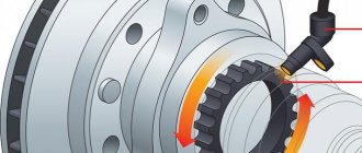
Mechanical Differences
Scheme of direct control of door locks.
All central locks in terms of functioning are reduced to 2 main types:
- mechanical central locking;
- remote door locking.
Mechanical closing of the doors occurs by turning a regular key in the lock; most often this function is located in the driver's door. If you close one, all the others are automatically blocked. The remote control is serviced using a key fob or a button on the ignition key. Of course, the mechanical option is simpler and more reliable. The remote control can sometimes jam for many reasons - from a dead battery and poor-quality mechanism to dead batteries in the key.
Initially, all locks were manufactured with a centralized control unit, however, over time, the appearance of additional functions, such as locking the trunk door or fuel hatch, required decentralization in control.
Today, manufacturers offer the option of a central lock combined with an alarm system. This option is quite practical, since all security systems work synchronously, which increases the level of vehicle safety. In addition, central locking with an alarm system is more convenient to install - you don’t need to go to a car service center several times or disassemble the car yourself.
Door partial closing switch
Each door latch contains a partial closure switch that is rigidly connected to the CJB. If the ignition is in power mode 4 (accessory power) or 6 (ignition) and a door is opened or not fully closed, the associated partial close switch disconnects ground from the CJB. The CJB transmits a message via the medium-speed CAN data bus to the instrument panel informing the driver that the door is not completely closed.
On vehicles with a low-level instrument panel, the door ajar symbol lights up. For more information, refer to the chapter: Instrument panel (413-01 Instrument panel, Description and operating principle).
On vehicles with a high-level instrument cluster, the door ajar symbol illuminates and a message is also displayed in the information center display. For more information, refer to the chapter: Information and Message Center (413-08 Information and Message Center, Description and Operation).
The door lock switch is also integrated into the vehicle's security system and is used as a vehicle intrusion detection device. For more information, refer to the chapter: Anti-theft system - active (419-01A Anti-theft system - active, Description and operation).
Using the door lock button
• To unlock the door, move the door lock button (1) to the “Unlock” position. A red mark (2) will be visible on the button. • To lock the door, move the door lock button (1) to the “Lock” position. If the door is properly closed, the red mark (2) on the door lock button will not be visible.
• To open the door, pull the door handle (3) towards you. • The front door cannot be locked if the ignition key is in the ignition switch and the door is open (if equipped). • The door cannot be locked if the smart key is in the vehicle and any of the doors is open.
CAREFULLY
— Door lock malfunction
If the power door lock fails, the occupant of the vehicle may use one of the following methods to escape:
• Try to open the door lock several times (either using an electric drive or manually), and at the same time pull the door handle towards you. • Use locks and handles of other doors, both front and rear. • Roll down the front door window and use the key to open the door from the outside.
Vehicles equipped with a central door lock switch (if equipped)
The lock is controlled by pressing this switch.
• When you press the front part (1) of the switch key, the locks of all vehicle doors will be locked. • When you press the rear part (2) of the switch key, the locks of all car doors will be unlocked. • If there is a key in the ignition switch or an electronic key in the vehicle and any door is open, pressing the front part (1) of the central locking switch will not lock the doors. • If the smart key is in the vehicle and one of the doors is open, the doors will not lock even if the front part (1) of the central door lock switch is pressed.
FOR YOUR INFORMATION
When doors are locked using the smart key or remote control, they cannot be unlocked from the central door lock switch.
CAREFULLY
— Doors
• While the vehicle is moving, its doors must always be completely closed and their locks locked to prevent accidental opening of the doors. In addition, locking the doors will make it difficult for unauthorized entry into the vehicle when it is stopped or slowed down. • Be careful when opening doors and make sure there are no approaching cars, motorcycles, cyclists or pedestrians that may be in the door opening area. Opening the door when there is an approaching obstacle may result in personal injury or property damage.
CAREFULLY
— Cars with unlocked doors
Leaving your car with the doors unlocked can make it a target for thieves or expose you or others to harm by someone hiding in the car while you're away. When leaving your vehicle unattended, always remove the key from the ignition, set the parking brake, close all windows and lock all doors.
CAREFULLY
— Children left unattended
The interior of a closed vehicle can reach extremely high temperatures, which can result in death or injury to unattended children or animals who are unable to escape from the vehicle.
Moreover, children may begin to play with parts of the car interior that are potentially dangerous to them, or be exposed to other types of dangers, for example, as a result of someone breaking into the car. Never leave children or animals unattended in a vehicle.
Door unlock system with shock sensor (if equipped)
When the airbags deploy due to an impact, all doors will automatically unlock.
Door locking system while the vehicle is moving (if equipped)
All doors are automatically locked when the vehicle speed exceeds 15 km/h or 40 km/h.
Door unlock system when engine stops (if equipped)
All doors will be automatically unlocked:
Without electronic key system
When the key is removed from the ignition.
With electronic key system
When the eNGINe START/SToP (engine start/stop) button is in the off position.
FOR YOUR INFORMATION
Your authorized HYUNDAI dealer can enable or disable some of the following automatic door lock/unlock features:
• Automatic door locking when the vehicle is moving • Automatic door unlocking when the engine is stopped
Controlling door locks from outside the vehicle
• Turn the key against the direction of vehicle movement to unlock the locks, and in the direction of vehicle movement to lock them. • When locking (unlocking) the driver's door with the key, ...
Rear door locking device to prevent children from opening them
A special rear door locking device is designed to prevent children from accidentally opening them while inside the vehicle. This device must be used at all times...
Other on the site:
Electrical diagram of a Skoda Fabia car - 21 Simos control unit, lambda probe, air pressure and temperature sensor in the engine intake pipe, adsorber solenoid valve (engines 1.0 l, 37 kW and 1.4 l, 50 kW exhaust ...
Replacement fuse mounted on a panel in the engine compartment 1. Turn the ignition key and all other switches to the “OFF” position 2. Push down on the fuse panel cover and remove it 3. Check the removed fuse, if it is blown...
Removing the cylinder head assembly with the intake manifold and exhaust manifold PERFORMANCE ORDER 1. Disconnect the negative cable from the battery. 2. Bring the piston of the first cylinder to the TDC position on the compression stroke, then return the crankshaft back a few degrees. For …
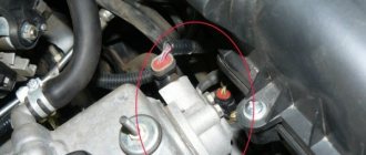
Emergency mechanical door lock
| Pos. | Spare part no. | Name |
| 1 | – | Secret mechanical lock |
| 2 | – | Emergency key |
| 3 | – | Left front door handle |
The remote control has an emergency access key hidden inside the remote control. There is a mechanical door lock in the outer handle of the left front door under a removable plastic cover. The door lock allows you to mechanically unlock and lock the left front door using the emergency access key in the event of a malfunction of the remote central locking function or a power failure to the vehicle.
When using a mechanical lock, the central locking system does not work and, if the vehicle's anti-theft system is activated, an audible alarm will sound when the door is opened. The emergency access key cannot be used to double-lock the vehicle or activate the anti-theft alarm.
Control points for locking and unlocking a Mitsubishi Karisma car
- Repair manuals
- Repair manual for Mitsubishi Karizma 1995-2004.
- Control points for locking and unlocking the vehicle
Locking and unlocking doors from outside the vehicle
| Rice. 1.1. Directions for unlocking and locking the door lock: 1 – initial position of the key; 2 – locking the lock; 3 – unlocking the lock |
To lock the vehicle, turn the key in the front door lock once to the lock position ( ).
To unlock the vehicle, turn the key in the front door lock once to the unlock position.
Locking and unlocking doors from inside the vehicle
To unlock the front door, pull the inside door handle towards you.
| Rice. 1.2. Positions of the door lock button: 1 – locking; 2 – unlocking |
When the door handle is pulled out, the front door opens even if it is pre-locked ( ).
Locking the front doors without a key
Press the inside lock button and close the door.
If the driver's door lock button is set to the lock position and the driver's door is closed while the key is left in the ignition, the doors will automatically unlock.
Child safety latches
| Rice. 1.3. Location of the child safety latch on the rear door: 1 – the latch is engaged; 2 – latch is disabled |
Locking the locks helps prevent the door from opening accidentally, especially when there are small children in the back seat. Door lock latches are installed on each rear door ( ).
If the locking latches are in the locked position, the rear doors cannot be opened from inside the vehicle. To open the rear door in this lock latch position, use the outside door handle.
If the door lock latches are in the latch disengaged position, the rear door locks will not lock.
Centralized door lock control system
Locking or unlocking the driver's or passenger's front door and trunk (or tailgate) using the key or interior lock button simultaneously locks or unlocks all doors, including the trunk (or tailgate).
On vehicles equipped with a remote control door lock system, when the trunk lid (or tailgate) is locked (unlocked), the remaining doors do not lock (unlock).
| Rice. 1.4. Switch for the centralized door lock control system: A – for vehicles with manually operated windows; B – for cars with electric windows; 1 – blocked; 2 – unlocked |
All doors can be individually locked or unlocked independently of each other using the corresponding interior lock button ( ).
↓ Comments ↓
1. Vehicle operation
1.0 Vehicle operation 1.1 Keys 1.2 Vehicle locking and unlocking controls 1.3 Power windows 1.4 Sunroof 1.5 Seats 1.6 Instruments and controls 1.7 Light, headlight and turn signal switch 1.8 Headlight leveling switch 1.9 Wiper and ohm switch reader windshield
2. Maintenance
2.0 Maintenance 2.1 Specifications and Data 2.2 General Information 2.3 Engine Oil 2.4 Changing the Engine Oil 2.5 Changing the Oil Filter 2.6 Automatic Transmission Fluid (ATF) 2.7 Coolant 2.8 Battery 2.9 Brake Fluid
3. Gasoline engines 4G9
3.0 4G9 gasoline engines 3.1 Technical characteristics and data 3.2 Changes in 4G92 engines (model 6B) since 1997 3.3 Basic data for adjustments and monitoring on 4G92 engines (model 6B) 3.4 Basic data for adjustments and monitoring 3.5 Checking and adjusting the drive belt tension generator 3.6 Changes in 4G92-MP1 engines since 2001 3.7 Lubricants 3.8 Checking and adjusting the tension of the drive belt of the power steering pump and air conditioning compressor 3.9 Checking and adjusting the clearances in the valve drive (SOHC)
4. FBQT diesel engines
4.0 FBQT diesel engines 4.1 Technical specifications and data 4.2 Lubricants 4.3 Checking and adjusting the accessory drive belt (vehicles with air conditioning) 4.4 Checking and adjusting valve clearances 4.5 Checking and adjusting fuel injection timing 4.6 Checking and adjusting engine idle speed 4.7 Checking and adjusting the increased speed of the engine crankshaft at idle when the engine warms up 4.8 Checking the compression 4.9 Adjusting the tension of the timing belt
5. F9Q diesel engines
5.0 F9Q diesel engines 5.1 Technical characteristics and data 5.2 Checking and adjusting valve clearances 5.3 Checking engine idle speed 5.4 Checking compression 5.5 Adjusting timing belt tension 5.6 Crankshaft pulley 5.7 Camshaft and camshaft oil seal 5.8 Engine oil pan 5.9 Crankshaft oil seals
6. Cooling system
6.0 Cooling system 6.1 Technical characteristics and data 6.2 General information 6.3 Checking the tightness of the cooling system 6.4 Checking the opening pressure of the radiator cap valve 6.5 Replacing the coolant 6.6 Thermostat 6.7 Water pump 6.8 Cooling system hoses and pipe 6.9 Radiator
7. Multiport injection system (MPI)
7.0 Multiport injection system (MPI) 7.1 Specifications and data 7.2 General information 7.3 Self-diagnosis function 7.4 Engine malfunction warning lamp 7.5 Cleaning the throttle body 7.6 Adjusting the throttle position switch and throttle position sensor (TPS) of vehicles without the system TCL 7.7 Adjusting the fully closed throttle position switch and accelerator pedal position sensor for vehicles with the TCL system 7.8 Adjusting the position of the throttle lever stop screw (Fixed SAS) 7.9 Adjusting the base engine idle speed
8. Direct fuel injection system (GDI)
8.0 Fuel direct injection (GDI) system 8.1 Technical data and characteristics 8.2 General information 8.3 Engine malfunction indicator lamp (“CHECK ENGINE”) 8.4 Relieving pressure in the power system 8.5 Checking the operation of the low pressure fuel pump 8.6 Cleaning the throttle body 8.7 Measurement low fuel pressure between the low and high pressure fuel pumps 8.8 Measuring the fuel pressure in the line between the high pressure fuel pump and the injectors 8.9 Checking the tightness of the supply system
9. Engine electrical equipment
9.0 Engine Electrical Equipment 9.1 Specifications and Data 9.2 General Information 9.3 Checking the Alternator Output Voltage Drop 9.4 Checking the Alternator Output Current 9.5 Checking the Voltage Regulator 9.6 Alternator 9.7 Starter 9.8 Direct Drive Starter 9.9 Reduction Starter
10. Clutch
10.0 Clutch 10.1 Technical characteristics and data 10.2 General information 10.3 Checking and adjusting the clutch pedal 10.4 Bleeding the hydraulic clutch 10.5 Clutch pedal 10.6 Checking the clutch release sensor 10.7 Hydraulic clutch drive for cars with gasoline engines 10.8 Hydraulic clutch drive for cars with diesel engines 1 0.9 Main cylinder hydraulic clutch drive for cars with gasoline engines
11. Manual transmission
11.0 Manual gearbox 11.1 Technical characteristics and data 11.2 General information 11.3 Checking the oil level 11.4 Changing the oil in the gearbox 11.5 Checking the operation of the reverse gear locking mechanism 11.6 Replacing the speedometer drive cable 11.7 Gear shift mechanism 11.8 Gear shift lever 11.9 Disassembling and assembling the shift lever gears
12. Automatic transmission
12.0 Automatic transmission 12.1 Technical characteristics and data 12.2 General information 12.3 Checking the fluid level in the gearbox 12.4 Replacing the fluid 12.5 Replacing the oil filter 12.6 Checking the starter locking mechanism 12.7 Checking the automatic transmission mode switching locking mechanism 12.8 Adjusting the selector cable 12.9 Adjusting the selector switch and cable control mechanism
13. Steering
13.0 Steering 13.1 Technical characteristics and data 13.2 General information 13.3 Checking the steering wheel play 13.4 Checking the torque that must be applied to start rotating the ball joint of the tie rod end 13.5 Checking the force that must be applied to turn the steering wheel on a stationary vehicle 13.6 Checking the self-return of the steering wheel wheels to the center position 13.7 Replacing the fluid 13.8 Bleeding air from the power steering hydraulic system 13.9 Checking the pressure generated by the power steering pump
14. Brake system
14.0 Brake system 14.1 Technical characteristics and data 14.2 General information 14.3 Checking and adjusting the brake pedal 14.4 Checking the brake light switch 14.5 Checking the functionality of the vacuum brake booster 14.6 Checking the functionality of the check valve of the vacuum brake booster 14.7 Checking the functionality of the rear brake pressure regulator 14.8 Checking the brake fluid level sensor 14.9 Bleeding the hydraulic brake drive
15. Front suspension and wheel drive shafts
15.0 Front suspension and wheel drive shafts 15.1 Technical characteristics and data 15.2 General information 15.3 Front wheel hub 15.4 Drive shaft 15.5 Repair of drive shafts 15.6 Checking and adjusting the angles of the front wheels 15.7 Front strut assembly 15.8 Repair of the front suspension strut 15.9 Lower arm of the front suspension
16. Rear suspension
16.0 Rear suspension 16.1 Technical characteristics and data 16.2 General information 16.3 Rear wheel hub 16.4 Checking and adjusting the angles of the rear wheels 16.5 Corrective, upper and lower arms of the rear suspension 16.6 Replacing the bushing of the lower arm 16.7 Trailing arm of the rear suspension 16.8 Rear strut 16.9 Repair of the rear strut
17. Body
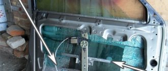
17.0 Body 17.1 Technical data 17.2 General information 17.3 Repair of minor body damage 17.4 Repair of major body damage 17.5 Front fender 17.6 Fuel filler flap 17.7 Replacing the windshield and fixed windows 17.8 Adjusting the door installation position 17.9 Adjustment in the event of malfunctions in the window lift mechanism
18. Air conditioning system
18.0 Air conditioning system system 18.1 Technical characteristics and data 18.2 General information 18.3 Safety measures 18.4 Search and elimination of malfunctions 18.5 Noise arising during the operation of the air conditioner compressor 18.6 Verification of the refrigerant level through the observation window 18.7 Verification of the air conditioning compressor 18.8 Verification Working with tubes, hoses and their connections
19. Vehicle electrical equipment
19.0 Vehicle electrical equipment 19.1 Technical characteristics and data 19.2 General information 19.3 Electrical circuits 19.4 Battery 19.5 Ignition switch and immobilizer 19.6 Identification code (ID) registration method 19.7 Checking the fuel level sensor 19.8 Checking the coolant temperature sensor 19.9 Instrument cluster
20. Electrical circuits
20.0 Electrical circuits