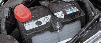
Signs of poor ground contact in KIA Rio 3. We check and fix it ourselves!
During the operation of Kia Rio 3rd and 4th generations, many owners have a very common problem: poor body or engine weight. As a result of high contact resistance, problems may arise with the vehicle's electrical wiring, instability of engine operation, and even problems with starting. There may be several
reasons for a bad “ground” – corrosion of wires or terminals (on the body and battery);
– corrosion of the place where the terminals are attached to the body (rust, paint on bolts and threads);
– break in one of the ground wires.
Broken streamer 918604L200 due to improper installation
Signs of poor body and engine mass
For many, poor body or engine weight begins to manifest itself as strange things when operating your Rio, for example, a suddenly dead battery due to an incomplete charge or an unstable idle. The problem may only appear under certain conditions, such as wet weather or winter. Here are some signs of poor vehicle ground contact:
- Increased fuel consumption
- Uneven engine operation
- Problems with starting the engine, especially in winter when higher starting currents are needed
- Incorrect operation of sensors
- Battery not fully charged
- Malfunction of electrical appliances and failure of fuses
- and others
How to check the quality of the “mass”?
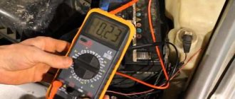
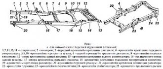
Any check should begin with an external inspection and make sure that the wires are not broken. We check the three main cables: the wire from the battery to the body, the ground wire between the engine and the right “glass”, between the gearbox and the body (located under the engine air filter housing). If there is no external damage, you need to take a multimeter and measure the resistance. We take measurements between the “-” terminal of the battery and the body, engine, in the range of up to 200 Ohms.
Important! Measurements are taken only with the vehicle turned off. Measurements are made only in a de-energized area!
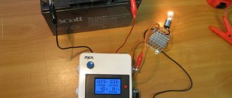
The multimeter readings should be within 1-2 ohms, preferably less. It is important not only resistance at a specific moment, but also that there is good contact at all times, regardless of the weather and time of year. This type of fault must be looked for using more sophisticated equipment, for example, an automotive oscilloscope.
Now we check the connections, the bolts should be well screwed to the body and should not dangle. The fastenings of the terminals to the body must be free of rust, and the terminals themselves must be free of oxides; their condition greatly affects the quality of the contacts.
What to do if the engine “mass” is bad?
If the wires are torn or heavily oxidized, they can simply be replaced; the original wires are quite expensive, so you can choose analogues or buy used braids in good technical condition at a disassembly site, for example, on this site. If the bolts and their mounting holes are rusty, it is enough to replace the terminal mounting bolts and process the threads, removing rust and paint residues from them. With all these procedures, it is necessary to treat all connections and the terminal with a special contact lubricant, which will improve conductivity, reduce resistance and protect against rust.
Rusty earth scythe mounting bolts
Numbers of original wires according to the catalog: Hyundai / KIA 918604L000, “-” battery - body Hyundai / KIA 918604L300, gearbox - body Hyundai / KIA 918604L500 (previously 918604L200), engine - body
The article shows only the main ground cables installed in KIA Rio 2011, 2012, 2013, 2014, 2020, 2020, 2017 model years, but do not forget that many other systems and units are connected to the ground with their own individual wires.
Bad ground on engine symptoms
Subscribe to topic
Notification by e-mail about replies to a topic during your absence from the forum.
Subscribe to this forum
Notification by e-mail about new topics on the forum during your absence from the forum.
Download/Print theme
Download the theme in various formats or view a printable version of the theme.
Let's try to figure out what weak spots for mass are on VAZ 2114 vehicles with an engine capacity of 1.5 and 1.6 liters.
1. Battery and ground.
The negative battery lead has a branching into two more different wires. The one that has significant thickness extends from the negative charge to the metal body of the engine. If the contact is poorly secured, the battery charge is not supplied in full and the starter cannot develop full power. The electronic control unit begins to slow down, because its mass is tied to the engine. Among other things, there is a possibility of poor performance of other spare parts and engine components, such as turbines, turbochargers, various sensors, etc.
At the place where the battery negative is attached to the engine, check how two nuts are tightened, and a contact is secured between them on the engine. Loosen the nut on the outside and tighten the one on the inside, then tighten the one on the outside as well.
A second, thinner battery cable is attached to the body near the battery.
This wire is the source for all energy-consuming components of the car. Check the nuts for tightness on the battery terminal and on the body.
2. Weight of the electronic engine control system.
For vehicles on which 1.5 liter engines were installed, the mass for the electronic control system comes from the engine housing and plugs, which are located on the right side of the head.
For cars with an engine capacity of 1.6 liters, the weight comes from a stud, which is welded and attached to the dashboard frame made of metal with a tunnel on the floor located under the ashtray. As practice shows, this pin is loosely tightened and is painted over at the factory. Over time, the stud becomes loose, which can lead to voltage drops in some sensors when the fan is turned on, and this can cause instability in speed.
Lost ground on the car: what does it mean and how to fix it
“The “mass” has disappeared!” – this is the spell we most often hear when contacting auto electricians with any malfunctions in the electrical equipment of the car. What is useful to know about the “mass” in a car, and how to fix it yourself if it disappears?
Two wires or one?
To connect the payload to a power source, two wires are required - even a schoolchild knows about this (although Nikola Tesla thought otherwise...). The most obvious example, quite possibly the one right next to you right now, is a table lamp plugged into an outlet. The few consumers of electricity on the first cars of the late 19th and early 20th centuries were switched on in approximately the same way. The scheme is simple, reliable and quite viable.
However, as soon as the production of cars became at least somewhat widespread, the commercial thought of industrialists immediately went in the direction of economy and optimization, and the number of wires in the car was immediately halved - the metal mass of the body began to be used as one of the wires - in common parlance the same “mass” "
The extremely simplified, but quite clear picture above on the right shows a modern car electrical circuit - when the “ground” is the negative wire of the on-board network. However, this was not always the case... Until approximately the 50s of the twentieth century, automakers used both minus and plus as “mass”.
Standards in the automotive industry had not yet been established, and from an electrical point of view there was absolutely no difference whether to run a plus or a minus on the body. However, by the middle of the century, observations revealed more noticeable corrosion damage to the bodies of those cars in which the “mass” was precisely a plus! It turned out that in this case, electrochemical corrosion develops more intensively, due to the direction of movement of electrons in the electrical circuit - from plus to minus. As a result, the plus “mass” was universally abandoned in favor of the minus one – especially since this did not require the slightest additional investment in production.
Weight of ECU VAZ 21124
I came across an article by McSystem. Actually, here it is below
In January - about Januarys. Again and in detail about the ECM-ECU masses
One of the rather serious problems affecting the stable operation of engines controlled by the January ECU (7.2, 7.2+, M73, 7.9.7) is the “mass problem” of the ECM. Moreover, the point is not so much in bad (or uncrimped) contacts and their fastenings, but rather in the rather incorrect wiring of the ECM harness itself. And the solution is not in “pulling a fancy cable (KG-25 or 50)” to the ECU. Therefore, this material will be devoted to a technically competent approach to solving this problem. What is described below is a kind of compilation, or an attempt to “chew” what has been published more than once, in particular on ChipTuner.ru, and to convey to readers the specifics of solving this problem. The articles by I.N. turned out to be the most complete and informative. Skrydlova, (aka Aktuator) “About the masses”, “MASS: AN UNEXHAUSTABLE SOURCE OF GLITCHES” “ONCE AGAIN ABOUT THE MASSES” ©Oleg Bratkov. Many years ago, having read and comprehended what was written, I implemented it on my typewriter. I completely agree with the conclusion of the author (aka Aktuator): “All the assurances of AVTOVAZ OJSC about improving the quality of electrical connections in manufactured vehicles are not worth a penny. In most cases, it is possible to achieve normal operation of the engine under the control of the ECM I 7.9.7 and January 7.2 only by carrying out additional, and not accepted by the manufacturer as a warranty, work to change the electrical circuit of the car.”
So, on to the topic! Classic ECM 21124 with ECU January 7.2(+) or M7.9.7 Electrical connection diagram of ECM EURO-2 M7.9.7, January 7.2 LADA 2110 with engine 21124. 21124-1411020-30, 21124-1411020-31.32
Fig. 1 ECM 21124 January 7.2, M7.9.7 Noticed, often described and characteristic problems - unstable idle speed, freezing speed, “jerking” of the engine at start and operation of the cooling fan, unreasonable jumps in the electrical parameters of the ECM during diagnostics. And this is not the entire list. And the whole problem is a rather incorrect wiring of the harness masses, not in relation to the body, but to the ECU. Therefore, in this article you will not see recommendations for tightening the “hoses” of additional mass to the ECU, due to its complete uselessness. This is not a newfangled “razmasovka” or “razminusovka”... Don’t get your hopes up!
The main idea voiced by the authors is that the wiring of the power lines of the ECU and fan and low-current sensor masses is fundamentally incorrect. Rice. 12
Fig.2 Ground connections of the ECM. S6, S7, S8
The sensors must be connected to the ground bus of the ECU board and not have contact with the body! There should be no flow of pulsed and direct currents of the ECU and IM in the sensor mass circuit. And the ECU is securely connected to the body. The rationale is to eliminate the influence of ECU currents (pulse and constant) and fan current on the reliability of sensor readings. Classic approach with data collection and processing systems! But not from AvtoVAZ designers, as usual... Now, in order
Fig. 3 Masses according to AvtoVAZ, or how not to do it
1. The ECU masses are combined into three crimps S6, S7, S8, which are combined with each other and TWO bends are already made from them to the body studs B3, B4. 2. A switched minus fan with a rated current of 12A is connected to S6, and at the peak at start - all 20A! ! ! Which in itself is terrible! 3. All this is connected (screwed) to the ECU bracket, which in turn is very flimsily connected to the body. The engine ECM consists of sensors and actuators (AM). Sensors can be easily divided into analog and discrete. Analogue – mass air flow sensor, air pressure sensor, diesel sensor, DD. The output signal of these sensors is a voltage in a certain small range, usually 0 - 5V. For this group, any (even small) interference has a serious impact on the result. Discrete ones - DC (to some approximation), DF, DS (Speed Sensor) - are less critical to interference, because the output signal has two fixed levels high and low, and intermediate levels are not interesting to the ECU. Actuators - ignition coils, injectors, canister valve, DC heating, IAC, relays and other sources of large pulsed and direct currents along the negative (mass) bus of the ECU. To understand what the developers were up to, let’s look at the diagram in Fig. 3 – this is a fragment of the main ECM diagram in expanded form. It immediately catches your eye - the masses of the most sensitive and responsible sensors, mass air flow sensors and diesel fuel sensors, are wired, although there are separate pins for them, 36 and 35, respectively. For what? Silence in response! S6-S7-S8 are connected by jumpers, which makes the situation even worse.
Fig.4 Equivalent circuit in drain
A little theoretical background. Note - the resistance of the ECU connection lines has very real values and consists of the actual resistance of the wire, the transition resistance of the contact in the connector, terminal, etc. And the dimension of these quantities is milliOhms (1000 mOhm = 1 Ohm). In the diagram this is indicated as an equivalent resistor Rm, Rm1, Rm2. For reference: Resistance of 1 m of copper wire with sections 0.35 mm² - 45 mOhm, 0.5 mm² - 35 mOhm, 0.75 mm² - 25 mOhm. Well, there are no “zero resistance wires”! (Whoever managed to buy them, please remain silent)
When the ECU is operating, the current consumption of the ECU itself consists of the consumption currents of the ECU itself and its IM, especially the coils and injectors. Its pulse component reaches 10A, its constant component is about 1.5-2.5A. This current flows through the “mass terminals” of the ECU, “ECU ground” and “sensor ground,” which is fundamentally wrong. Fig.4 At very real resistances Rm, a voltage drop is formed between the connection point to the body and the negative bus (housing) of the ECU - Ucm1. In addition, the flowing current creates a bias voltage drop Ucm2 between the negative bus (housing) of the ECU and the connection point of the sensors. This tension is the root cause of all problems! It is summed with the useful voltage coming from the sensor and enters the measuring unit of the ECU - ADC (Analog-to-Digital Converter). Umeas = Usensor + Ucm2 And then the program processes the already digitized “false” result. With all the ensuing consequences. That is, the problem is not so much the reliability of connecting the ECU to the body, but the incorrect distribution of masses in the harness.
Engine demining and signs of poor grounding
An electrical circuit needs a good ground to function properly. Many people ask - why is engine demining necessary? The answer is - poor electrical grounding can affect one or more electrical systems, because it forces the current to look for other simpler paths. This can cause all sorts of problems with lights, sensors, modules and other electrical and electronic components, all of the above is also true to answer the common question - what is the purpose of mass in a car.
Causes and symptoms of poor engine grounding
Engine malfunction may be caused by:
- Loose, rusty, or damaged ground terminals or wires
- Weak, damaged or corroded battery ground terminal
- Poorly installed or repaired components
Symptoms of a poor motor ground may include:
- Dim lights
- Flickering lights
- Electrical devices operate erratically
- Faulty fuel pump
- A slipping or burnt A/C compressor clutch
- Intermittent sensor failure
- Throttle or transmission cables are damaged
- Hard start
- Low battery
Often bad grounds are relatively easy to diagnose and correct, usually in a matter of minutes. You can diagnose and repair in your own garage using just a digital multimeter (DMM) and some common tools.
If you don't know where all the engines or transmissions are located in your vehicle, you may want to consult your vehicle's repair manual. You can get a relatively inexpensive copy through Amazon. Haynes manuals come with step-by-step procedures for many maintenance, repair and troubleshooting projects. This way, you will recoup your small investment in a short time.
FINE. So grab your multimeter and let's find those bad grounds in your car.
Corrosion or damage to grounding straps can cause electrical accessories to malfunction.
Electrical ground diagnostics
The following sections are divided between tests. This will make it easier to test the starter and accessory ground paths to identify common electrical system problems.
Here are some important points to keep in mind when troubleshooting your car:
- When testing, make sure the terminals are attached to an unpainted surface. You have to connect to bare metal. Paint, corrosion, greasy surfaces, frayed or broken wires, and loose connections are the main causes of poor automotive finishes.
- Some vehicles use a separate chassis ground wire in addition to the main one (black battery cable) that runs from the negative battery terminal to the chassis. This is for headlights, accessories and other electronic equipment.
You can use the remote starter switch to crank the engine while testing your vehicle. Connect the switch to the battery and the "s" terminal on the starter solenoid or remote starter relay.
Where is the ECU ground located?
The ECU mass is usually arranged like this. The engine control unit housing itself is screwed to a metal bracket, which, in turn, is screwed to the car body. Also, a separate ground wire is removed from the ECU connector, which is connected to the engine via the starter mounting bolt.
Everything is simple and reliable. But in reality, over time, the voltage begins to drop in this section of the circuit, slowly but surely, disrupting the operation of the system.
This article is a logical continuation of the previous article, where we checked the voltage drop in the ground circuit from the engine to the body. I advise you to familiarize yourself with it first, and then continue to implement the modification given below in this article.
In general, last time we found a voltage drop in the ground circuit from the engine to the ECU
And on this page we will solve this problem by laying additional mass from the ECU to the engine and from the generator to the body.
We will look at the mass from the generator in another article very soon (I’ll give a link here), and on this page we will focus on the additional mass of the ECU.
Checking grounding in a car
Electronic modules and many electrical components in the engine, transmission and passenger compartment use the body as an electrical ground. This test checks for unwanted resistance at these points, including the secondary ground between the battery and chassis used by some older models. If necessary, consult your vehicle's repair manual.
- Connect the black lead of your meter to the battery (-) terminal and the red lead of your meter to where the wire connects to the body.
- Have a helper crank the engine for a few seconds.
You should get a voltage drop of 0.2V or less. If the voltage drop is higher, proceed to the next steps.
- Move the red lead of your meter to the terminal on the end of the secondary ground wire. Take voltage drop readings.
If you get a reading higher than 0.2 volts, proceed to the next step.
- Move your meter's red test lead to the next terminal and ground point. Take voltage drop readings at each point.
When you get a reading around 0.2V or lower, the unwanted resistance is between this and the previous test point. Check for corrosion, broken or loose wires.
Also, check the voltage drop on the ground circuits that connect the engine to the chassis.
Search, check and replace transfer grounds if necessary.
Vesta
One of the owners noticed that when the cooling fan was turned on, the engine shuddered slightly. After inspecting the engine compartment, it turned out that the Vesta was missing a wire going from the battery to the engine. The “ground” to the engine comes only from the body, on one side from the bottom of the spar to the gearbox, and on the other hand from the spar to the generator, and from the battery the wire goes to the body. For example, on the 2020 Renault Sandero Stepway the wire from the battery goes directly to the engine.
Required
: wire (article AX632).
Installation procedure
:
- Remove the air filter box and intake (for convenience).
- Stretch the wire from the battery to the thermostat stud (but it’s better to go to the stud on the engine itself, see above).
The on-board computer used to show a voltage of 14.0-14.1 V, now it’s 14.1-14.3 V. I don’t notice any shuddering when the fan is activated.
It’s similar on other LADA models.
Let us remind you that the voltage in the car's electrical system should be 14.2-14.4 Volts.
Checking weight in a car
Transmissions on some vehicle models are equipped with a chassis or protective shield for modules, sensors, and solenoids (relays). You can also test these grounds using your digital multimeter.
- Check the voltage drop between the transmission and the negative terminal of the battery. The voltage drop should be 0.2V or lower.
- Check individual chassis grounding by checking the voltage drop across each ground terminal on the transmission. The voltage drop should be 0.2V or lower.
Clean, repair or replace the transmission ground as necessary. Remove grease, rust and paint from ground terminals or replace damaged ground straps.
General Voltage Drop Values
Choke cables and other equipment can be damaged when high electrical current cannot find the correct path back to ground.