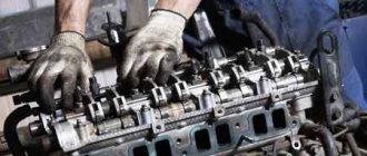
Removing steering column switches Renault Logan
We carry out the work when removing the steering column, instrument panel and when replacing steering column switches. Disconnect the wire terminal from the negative terminal of the battery. We install the front wheels in a position corresponding to the straight-line movement of the car. Remove the steering wheel (see “Removing the steering wheel”).
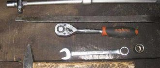
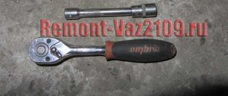
Using a Torx T-20 wrench, unscrew the two self-tapping screws securing the steering column casings.
Remove the upper steering column cover, overcoming the resistance of two clamps.
Remove the lower steering column cover.
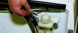
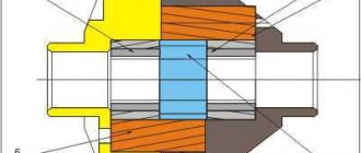
Fastening elements for steering column casings: 1 - plate nuts; 2 — clamps; 3 - self-tapping screws For the electrical connection of the driver's airbag installed on the steering wheel with the electrical equipment of the car, a conventional sliding contact cannot be used to avoid sparking and unintentional deployment of the airbag. Therefore, the car uses a device with a so-called spiral cable, which works on the principle of a tape measure.
In the cylindrical plastic case 2 of the device, made in the housing of the connector of the steering column switches (for clarity, shown on the removed connector of the steering column switches), several turns of metal-plastic tape 4, which is an electrical conductor, are laid spirally
Spiral cable One end of the cable strip is connected to the car electrical wiring harness block through a connector located on the steering column switch connector housing. The other end of the cable is brought out to the protruding lead 3 of the drum 5 of the device and is connected through block 1 to the airbag. The device drum driver fits into the hole in the steering wheel hub. When the wheel rotates, the leash turns the drum, and with it the cable strip, which is located in a cylindrical body either at a larger or smaller radius. From its middle position, the drum with a leash in the device can be rotated in each direction until it stops by three full turns. This prevents the electrical conductor from breaking when the steering wheel is rotated from the neutral position by 2.25 turns in each direction on a car without power steering, and a slightly lower number of revolutions on a car equipped with power steering. Before removing the steering column switch connector from the steering column, for ease of subsequent assembly, it is better to block the device drum from turning. To do this, if necessary, turn the drum at a slight angle, aligning the depression between the two protrusions of the drum with the groove of the housing...
...and insert a wooden wedge.
Using a Torx T-20 wrench, unscrew the connector securing screw a few turns. By pressing the head of the screw along its axis...
...move the connector from the steering column.
We disconnect two blocks of wire harnesses from the steering column switches and one block of wires from the connector on the connector body... ...and remove the connector with the switches as an assembly. We install the connector with the steering column switches in the reverse order. When installing the connector, we combine...
...protrusion in the socket of the connector body...
...with a groove at the end of the steering column pipe. Each steering column switch can be removed individually without removing the connector. To do this, after removing the steering column covers and disconnecting the wiring harness block from the switch...
... use a Phillips screwdriver to unscrew the two screws securing the switch (for clarity, shown on the removed connector of the steering column switches).
Remove the left steering column switch from the connector. Similarly, remove the right steering column switch from the connector. We install the steering column switches in the reverse order. When installing the steering column covers...
...we pass the self-tapping screws for fastening the casings through the holes in the bosses of the housing of the steering column switch connector (for clarity, it is shown on the removed casings and the steering column switch connector).
Fuses and relays VAZ 2110
F1 - 5A - License plate lamps. Instrument lighting lamps. Side light indicator lamp. Trunk light. Left side side light lamps F2 - 7.5A - Left headlight (low beam) F3 - 10A - Left headlight (high beam) F4 - 10A - Right fog lamp F5 - 30A - Door window electric motors F6 - 15A - Portable lamp F7 - 20A — Electric motor of the engine cooling system fan. Sound signal F8 - 20A - Rear window heating element. Relay (contacts) for turning on the heated rear window F9 - 20A - Recirculation valve. Windshield and headlight cleaners and washers. Relay (winding) for turning on the heated rear window F10 - 20A - Reserve F11 - 5A - Side light bulbs on the right side F12 - 7.5A - Right headlight (low beam) F13 - 10A - Right headlight (high beam). Indicator lamp for turning on the high beam. F14 - 10A - Left fog lamp F15 - 20A - Electric seat heating. Trunk lock lock F16 - 10A - Relay-breaker for direction indicators and hazard warning lights (in emergency mode). Hazard warning lamp F17 - 7.5A - Interior lighting lamp. Individual backlight lamp. Ignition switch illumination lamp. Brake light bulbs. Clock (or trip computer) F18 - 25A - Glove box lighting lamp. Heater controller. Cigarette lighter F19 - 10A - Door locking. Relay for monitoring the health of brake light lamps and side lights. Direction indicators with warning lamps. Reversing lamps. Generator excitation winding. On-board control system display unit. Instrument cluster. Clock (or trip computer) F20 - 7.5A - Rear fog lamps
K1 – relay for monitoring the health of light bulbs; K2 – front wiper relay; K3 – repeater and alarm relay; K4 – low beam relay; K5 – high beam relay; K6 – additional relay; K7 – relay for turning on the heated rear window; K8 – backup relay
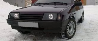
Let's be honest - the VAZ 2110 does not have the most beautiful “native” instrument panel, either on the first cars or on the “improved” ones. Therefore, many owners of this model are trying to make it more modern and somehow decorate it (with LEDs, beautiful lights, etc.).
But, before you decide on some kind of upgrade, it is necessary that you have before your eyes the pinout of the instrument panel for the VAZ 2110, otherwise you can simply get lost in a heap of wires, sensors and buttons. Moreover, it will be useful regardless of whether you completely change the panel, or simply make some additions to the dashboard of your VAZ 2110.
Instrument panel VAZ 2110
Checking and replacing steering column switches on a VAZ 2110 Lada
/ VAZ/ vaz-2110/ Electrical equipment/ Lighting, light and sound alarms/ Checking and replacing steering column switches
7.8.7. Checking and replacing steering column switches
Turn signal and headlight switch type 69.3709
| Turn signal and headlight switch contact numbers |
Windshield wiper and washer switch type 70.3709
| Wiper and washer switch contact numbers |
Steering column switch lever positions
| Bold lines show the initial positions, thin lines - fixed and dotted lines - non-fixed positions of the levers. |
| EXECUTION ORDER | ||||||||||||||||||||||||||||||||||||||||||||||||
Contact closure at different positions of the turn signal and headlight switch levers
* Non-fixed position. Contact closure at different positions of the windshield wiper and washer switch lever
* Non-fixed position CommentsNo comments yet Leave a comment Cancel reply |