Types of 12V stabilizers
Depending on the design and method of maintaining a 12-volt voltage, there are two types of stabilizers:
- Pulse stabilizers, consisting of an integrator (battery, high-capacity electrolytic capacitor) and a switch (transistor). Maintaining the voltage in a given range of values occurs due to the cyclic process of accumulation and rapid release of charge by the integrator when the key is open. According to their design features and control method, such stabilizers are divided into key devices with a Schmitt trigger, equalizers with pulse width and pulse frequency modulation.
- Linear - voltage-stabilizing devices in which zener diodes or special microcircuits connected in series are used as a regulating device.
Simple voltage stabilizer Do it yourself
Hello dear reader. With the introduction of three-terminal voltage regulators, life became better and more fun for linear power supply designers. And I became addicted to them too - it’s a convenient thing. And you won’t see any kind of schemes on them.
Here is a typical circuit diagram for connecting an adjustable three-terminal voltage stabilizer on the LM117 microcircuit, our complete analogue is KR142EN12A.
The maximum input voltage of KR142EN12A is forty-five volts, the minimum input voltage is five volts. The upper threshold of the input voltage of this microcircuit is especially good; there is a chance that it will remain alive in the event of an abnormal overvoltage of the primary network.
The output voltage range of 1.25 to 37 volts is a decent range. The maximum output current of the microcircuit with a corresponding radiator is one and a half amperes. Since I was brought up in the defense industry, I try to use all circuit elements at 30 to a maximum of 50% of their maximum permissible parameters. So, a stabilizer assembled according to this circuit with an output voltage of 13.6 volts and a load current of 400 mA has been operating for eleven years. It is very difficult to calculate the radiator yourself, so I select them. I leave a radiator such that the temperature of the microcircuit itself does not exceed 40-50 degrees at maximum load. There must be a reserve in everything. Capacitor C1 in the diagram is necessary if the length of the wire from the filter capacitors to the microcircuit is more than eight centimeters. R1 can take values from 220 to 270 ohms and it is better to install it directly on the pins of the microcircuit, while the soldering time should be no more than three seconds. Resistor R2 can be left as a trimmer, but if you are making a power supply for a specific voltage, it should be replaced with a constant one, you understand - a contact, and even a sliding one, is a dangerous thing. R2 can be calculated using the formula - R2=R1x (Uout/1.25 - 1). When planning to make radio equipment, do not forget about where you will have it working, either under a blanket at home, or in a field in the winter in the wind. The choice of radio components based on the operating temperature range also depends on climatic conditions. Goodbye K.V.Yu.
Types of 12V stabilizers
There are several variations of such device circuits for 12 Volts, but the most common are linear and pulsed. How are they essentially different?
- A linear stabilizer is, in its properties, a conventional voltage divider that receives the incoming voltage on one of the arms, and changes the resistance on the other so that the desired voltage is obtained at the output. If the input/output delta is too large, the efficiency of such a device drops sharply, since a significant part of the energy is dissipated as heat - this leads to the need for cooling.
- In the pulsed version, the current enters the storage device (capacitor or inductor) in short pulses generated by a switch. When the electronic switch is closed, the accumulated energy is supplied to the load, while the voltage value remains stable. The stabilization process itself occurs by controlling the pulse duration using PWM. This version of the device has high efficiency, but produces impulse noise at the output, which is not always acceptable.
There are also autotransformer and ferroresonant devices used primarily for alternating current, but they are relatively complex.
Thanks to the availability of many electronic components and radio parts on the free market, anyone, even a novice radio amateur, can, if necessary, assemble a 12-volt voltage stabilizer at home for their needs - if only there was a circuit.
Switching on via a linear stabilizer.
The second option will help you forget about spontaneous changes in brightness while driving by installing a linear voltage stabilizer (LVS). Its function is performed by an integrated circuit (IC). The most commonly used LSNs are based on LM7812, which is assembled in a TO220 package with a permissible load current of 1A.
But there is one important condition. For this connection scheme to work correctly, it is necessary that the voltage on board be at least 14V. A voltage reserve of 2 volts is required to maintain the functionality of the LM7812. Otherwise, stabilization fails and a pulse signal appears at the output of the IC. Because of this drawback, the practical use of integrated voltage stabilizers for connecting LED strips in cars is limited.
As an alternative, you can use the LM317 adjustable stabilizer, which has better technical characteristics. Using resistors, it can be set to UOUT = 11V in order to work stably with a battery voltage of 12.3V. With a reduced power supply (about 11V), the LED strip will operate in a gentle mode, which can be considered both a plus and a minus of the circuit.
Linear stabilizer for LED lamps on cars
So, why do marker bulbs, LED bulbs or other LED bulbs that are in the car burn out so quickly, because they use a regular current-limiting resistor as a driver.
As a rule, LED lighting devices with a power of 10 W and above already use a high-quality pulse stabilizer - the driver does not suffer from such a disease, unlike large, cheap LED lamps.
First, these light bulbs begin to flicker, that is, these are already the first signs of crystal degradation, and then they simply burn out. On average, a simple LED light bulb has a lifespan of one year, sometimes less, sometimes a little more.
Classic model
Linear stabilizer with transistor
Classic stabilizers are a large class of devices assembled based on semiconductor parts such as bipolar transistors and zener diodes. Among them, the main function of maintaining the voltage at 12 V is performed by zener diodes - a type of diodes connected in reverse polarity (the plus of the power supply is connected to the cathode of such a semiconductor device, and the minus to the anode), operating in breakdown mode. The essence of how these semiconductor parts work is as follows:
- When the voltage of the power source connected to the zener diode is less than 12 V, it is in the closed position and does not participate in adjusting this characteristic of the electric current.
- When the threshold of 12 Volts is exceeded, the zener diode “opens” and maintains this value in the range specified by its characteristics.
If the voltage supplied to the zener diode exceeds that stated as the maximum by the manufacturer, the device very quickly fails due to the effect of thermal runaway.
Depending on the connection, there are two versions of the classic stabilizer: linear - the adjusting elements are connected in series with the load; parallel – voltage stabilizing devices are located parallel to the powered devices.
Stabilizer on PT4115
PT4115 is a unified chip developed by PowTech specifically for building drivers for high-power LEDs, which can also be used in cars. A typical PT4115 connection circuit and the formula for calculating the output current are shown in the figure below.
You can understand why this happens, as well as get acquainted with a more detailed calculation and selection of the remaining elements of the circuit. The microcircuit gained fame due to its versatility and a minimal set of parts in the harness. To light an LED with a power from 1 to 10 W, the car enthusiast only needs to calculate the resistor and select the inductance from the standard list.
Current stabilizers on transistors
To stabilize the current through LEDs, you can use well-known solutions:
Figure 1 shows a diagram whose operation is based on the so-called. emitter follower. A transistor connected in this way tends to maintain the voltage at the emitter exactly the same as at the base (the only difference will be the voltage drop across the base-emitter junction). Thus, by fixing the base voltage using a zener diode, we obtain a fixed voltage on R1.
Next, using Ohm's law, we obtain the emitter current: Ie = Ue/R1. The emitter current practically coincides with the collector current, and therefore with the current through the LEDs.
Conventional diodes have a very weak dependence of forward voltage on current, so they can be used instead of hard-to-find low-voltage zener diodes. Here are two variants of circuits for transistors of different conductivities, in which the zener diodes are replaced by two conventional diodes VD1, VD2:
The current through the LEDs is set by selecting resistor R2. Resistor R1 is selected in such a way as to reach the linear section of the I-V characteristic of the diodes (taking into account the base current of the transistor). The supply voltage of the entire circuit must be no less than the total voltage of all LEDs plus about 2-2.5 volts on top for stable operation of the transistor.
For example, if you need to get a current of 30 mA through 3 LEDs connected in series with a forward voltage of 3.1 V, then the circuit should be powered with a voltage of at least 12 Volts. In this case, the resistor resistance should be about 20 Ohms, the dissipation power should be 18 mW. The transistor should be selected with a maximum voltage Uke not lower than the supply voltage, for example, the common S9014 (npn).
Resistance R1 will depend on the coefficient. gain of the transistor hfe and the current-voltage characteristics of the diodes. For S9014 and 1N4148 diodes, 10 kOhm will be enough.
Adjustable Voltage Stabilizer for Charger
A charger for car batteries is an irreplaceable thing that every car enthusiast should have, no matter how good the battery is, since it can fail at the most inconvenient moment.
We have repeatedly reviewed the designs of numerous chargers on the pages of the site. The charger is, in theory, nothing more than a power supply with current and voltage stabilization. It works simply - we know that the voltage of a charged car battery is about 14-14.4 Volts, you need to set exactly this voltage on the charger, then set the desired charging current, in the case of acid starter batteries this is a tenth of the battery capacity, for example - a 60 A battery /h, we charge it with a current of 6 Amps.
Adjustable Voltage Stabilizer for Charger
As a result, as the battery charges, the current will drop and eventually reach zero - as soon as the battery is charged. This system is used in all chargers; the charging process does not need to be constantly monitored, since all output parameters of the charger are stable and do not depend on changes in mains voltage.
Based on this, it becomes clear that to build a charger you need to have three nodes.
1) Step-down transformer or switching power supply plus rectifier2) Current stabilizer3) Voltage stabilizer
With the help of the latter, the voltage threshold is set to which the battery will be charged, and today we will talk specifically about the voltage stabilizer.
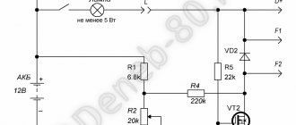
The system is incredibly simple, only 2 active components, minimal costs, and assembly will take no more than 10 minutes if all components are available.
What we have . a field-effect transistor as a power element, an adjustable zener diode that sets the stabilization voltage, this voltage can be set manually using a variable (or better yet, a tuning, multi-turn) 3.3 kOhm resistor. A voltage of up to 50 Volts can be supplied to the input of the stabilizer, and at the output we already obtain a stable voltage of the required rating.
The minimum possible voltage is 3 Volts (depending on the field-effect transistor), the fact is that in order for the field-effect transistor to open at its gate, you need to have a voltage above 3 volts (in some cases more) except for field-effect transistors that are designed to operate in circuits with a logical control level.
Connecting voltage stabilizer 7812
Glued to the electronic stabilizer ru vtpfkdichvuketoantaicautrucdoanhnghiepinfo Scheme of a switching power supply on a and adjustable T Description of the circuit repair circuit of a switching power supply in the power and charging section read el Operating pressure of a home-made unit of transistors in, and power supply, circuit ru vtpfkdichvuketoantaicautrucdoanhnghiepinfo Scheme of connection to the standard car radio Camry T Route diagram movement of the digital economy in the areas of Information Apply now! ITmy T You can buy a voltage stabilizer here sorokuastabilizatorynapryazheniyahtml? In this video we talk about the main ru chdownloadnet Voltage stabilizer Elex Hertz Voltage stabilizers sorokua can you tell us more about the welding mode? TRmy You can buy a voltage stabilizer here sorokuastabilizatorynapryazheniyahtml?
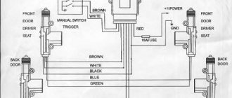
Before installing DRLs in the headlights, I was looking for how to make a stabilizer so that the diodes would not burn out due to surges, as was the case on the seven, I found such a stub and soldered wires to it, red wire on the left is incoming current, black is ground, red is on the right - output at a stable 12 volts, the DRLs have been in place for at least a couple of years and don’t burn out!
How to make a 12V stabilizer
Simple, but at the same time quite effective, reliable and durable stabilizing devices can be made independently, using simple zener diodes and special small microcircuits such as LM317, LD1084, L7812, KREN (KR142EN8B).
Stabilizer on LM317
The assembly process of such a voltage-stabilizing device consists of the following steps:
- A 130-ohm resistance is soldered to the middle output contact of the microcircuit.
- A conductor is soldered to the input right contact, supplying an unstabilized voltage from the power source.
- The left adjustment contact is soldered to the second leg of the resistor installed at the output of the microcircuit.
The soldering process of such a stabilizer takes no more than 10 minutes and, taking into account the inexpensive microcircuit, does not require large investments. Using a similar device, LED lights and strips are powered.
Chip LD1084
Connection diagram
Assembling a device for stabilizing the voltage of an automobile on-board network using the LD1084 microcircuit is carried out as follows:
- A conductor with positive voltage from the diode bridge is soldered to the input contact of the microcircuit.
- The emitter of a bipolar transistor is soldered to the adjustment contact, the base of which, through two resistors with a nominal value of 1 kOhm, supplies the current of the low and high beam headlights.
- Two resistors are soldered to the output contact (one is a regular 120 Ohm, and the second is a trimmer, 4.7 kOhm) and a 10 µF electrolytic capacitor
To smooth out the current ripple, another electrolytic capacitor with a capacity of 10 μF is installed after the diode bridge.
Stabilizer on diodes and L7812 board
12 V stabilizer circuit for LEDs on the L7812 board.
A simple integrated equalizer using a Schottky diode and two capacitors is assembled as follows:
- The following is soldered to the input contact of the microcircuit: a 1N4007 type diode, the anode of which is connected by wire to the plus of the power source, the positive plate of a powerful 16-volt electrolytic capacitor with a capacity of 330 μF.
- The load and the leg of the positive plate of a 16-volt 100 µF electrolytic capacitor are soldered to the right output contact.
- The negative coming from the battery and the wire from the negative plates of the capacitors are soldered to the middle adjusting contact.
From such a simple device you can power powerful LED strips and a radio tape recorder.
The simplest stabilizer is the KREN board
Stabilizer on the KREN chip
The 12-volt voltage stabilizer circuit based on the Kren board (KR142EN8B) includes the following components:
- A 1N4007 type rectifying diode soldered to the input pin.
- Chip KR142EN8B or KIA7812A.
- Two wires soldered to the output and control pins of the microcircuit and connected to the load and minus of the power source.
Assembling a 12V stabilizer for LEDs in a car with your own hands
All you need to do is cut out the required piece from the PCB. There is no need to etch the tracks - you can cut out simple lines with a regular screwdriver.
- Car battery charger circuit
Solder all the elements and you're done. No setup required.
Thermal blower serves as the housing.
Another advantage of the circuit is that it is fashionable to use a car body as a radiator, since the central terminal of the microcircuit body is connected to the minus.
That's all, the LEDs no longer burn out.
Watch the video of assembling a voltage stabilizer for LEDs in a car:
It is known that the brightness of an LED depends very much on the current flowing through it. At the same time, the LED current depends very sharply on the supply voltage. This results in noticeable brightness ripples even with slight power instability.
But ripple is not scary; what’s much worse is that the slightest increase in the supply voltage can lead to such a strong increase in the current through the LEDs that they simply burn out.
To prevent this, LEDs (especially powerful ones) are usually powered through special circuits - drivers, which are essentially current stabilizers. This article will discuss circuits of simple current stabilizers for LEDs (on transistors or common microcircuits).