External generator voltage regulator
Greetings!
I propose to make an external voltage regulator for a car generator.
What are the benefits of an external voltage regulator? The first is that it can be located in a more accessible place than on the generator itself. On some cars, in order to gain access to the generator, it is necessary to disconnect the muffler exhaust pipe, and in order to remove the generator itself, you also need to remove one axle shaft from the gearbox. In addition, if the generator is located next to the exhaust pipe of the muffler, it heats up more. The operating conditions of both the generator itself, the diode bridge, and the voltage regulator are very harsh.
The second advantage is that you can easily adjust the output voltage of the generator if it turns out to be lower (for example, due to a drop on the connecting wires) or higher than that required for recharging the battery.
Briefly about how the voltage regulator works.
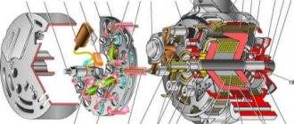
field coil alternators, the output voltage is controlled by varying the current flowing through the field coil. In most cases, the field winding is wound on the rotor. The current in the winding creates a magnetic field. When the rotor begins to rotate, the magnetic field rotating with it induces a current in the stator winding. The greater the current through the field winding, the higher the voltage at the generator output. The field winding leads are connected to slip located on the generator shaft, and the field current is supplied through carbon brushes .
Without regulating the current through the excitation winding, the voltage at the generator output can reach large values (more than 200 V). Naturally, such voltages, to put it mildly, are not needed to recharge a car battery. Typically, a voltage of 13.5 to 14.5 V is maintained in the vehicle’s on-board network when the engine is running (rotating generator rotor). The principle of regulating the output voltage of the generator on a vehicle is based on changing the time the field winding is on. In other words, if the output voltage is outside the permissible parameters, the regulator disconnects the winding from the power circuit. If the output voltage does not exceed the permissible value, then the excitation winding is connected to the power supply.
There are two schemes for connecting the regulator to the excitation winding. The first is when the winding is constantly connected to the + of the source, and the regulator switches the other terminal of the winding with the minus (ground). And the second circuit - the excitation winding is constantly connected to the negative contact of the source. In this case, the regulator switches the second terminal of the winding from the + source. The first circuit is also called circuit A, the second - circuit B. By analogy with switches on field-effect transistors, the first circuit is the lower key, and the second is the upper key.
The diagram of the simplest regulator and its connection to the battery is shown in the figure:
The regulator is connected by contact B+ to the contact of the same name on the generator. The negative contact of the regulator is connected to the generator housing. Or the regulator is connected directly to the battery ( B+ to the positive terminal, and common to the negative terminal of the battery). Contacts F1 and F2 of the regulator are connected to the excitation winding (brush terminals). The divider of resistors R1 , R2 and R3 sets the voltage at which the zener diode VD1 1N4742A with a stabilization voltage of 12 V.
As long as the voltage coming from the resistor R2 is less than 12 V, the zener diode is closed. The voltage at the base of VT1 is not enough to open this transistor. At the gate of field-effect transistor VT2 , thanks to resistor R5 , there is a supply voltage that opens the transistor. Due to this, current flows through the field winding. As soon as the voltage from the divider exceeds 12V, the zener diode VD1 will break through.
at the base of transistor VT1 , which will open it. Now the current from the gate of field-effect transistor VT2 will flow through the open transistor and the gate will not receive anything. Therefore, VT2 will close and disconnect the field winding from the power source. By using variable resistor R2, you can change the response threshold of the regulator, thereby changing the output voltage of the generator.
About the components of the circuit.
Transistor VT1 type BC547 or similar. VT2 IRF1404 . Although this transistor is designed for a current of up to 202 A, it gets hot during prolonged operation. Therefore, it is better to attach a radiator to it. VD1 1N4742A – 12 V zener diode .
The connection between the regulator and the generator on a car is slightly different from the diagram above. On a car, the wire from the charge indicator lamp goes from the dashboard to the generator, so it’s easier not to disconnect this wire from the generator (to connect it to the regulator), but to run a separate wire from the terminals of the additional rectifier. This wire is connected to the contact of the charge indicator lamp.
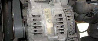
For example, a generator from Delta Autotechnik. In this generator, the regulator is connected to the excitation winding with a lower switch, i.e. one terminal of the winding is connected to the output of the rectifier using additional diodes (the same terminal is connected to the contact to which the charge lamp is connected), and the other is switched to negative by the regulator.
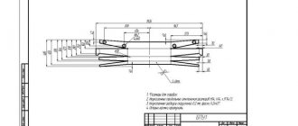
To disconnect the original regulator from the excitation winding, it is necessary to disconnect the brush lead, which is connected to the regulator output (F2 in the figure). For example, an insulating pad made of textolite (see figure).
Pin D+ must be left connected to the pin of the native regulator, because this pin also goes to contact L. In total, 3 wires will go from the car generator to the external regulator (in the diagram below in a dotted rectangle): 2 wires from the brush leads and 1 wire from the contact of the charge indication lamp.
A +12 V and -12 V can be taken directly from the battery.
Discuss on the forum.
See also:
External generator voltage regulator updated: November 23, 2019 by Deneb-80
Replacing the internal regulator in a Lucas generator
Before starting work, mark the contacts and remember the location of the gaskets.
Disconnect the battery and remove the back cover of the generator. In most cases, this will require removing the generator itself (see the section Checking the generator and measuring the current). Disconnect the contacts (there may be two, three or four) and remove the metal tip, remembering the method of attachment.
The regulator itself may have two screws or one screw and several slots. When disassembling, be careful not to lose any screws or gaskets.
Some internal regulators have jumpers connecting the terminals to the housing.
They separate the alternator and battery when the ignition is turned off. You may have to loosen the screw that secures the jumper to move it out of the way. Note the small plastic spacer.
The new regulator may differ from the old one - for example, in the number of connecting wires.
Follow the manufacturer's instructions to avoid mistakes when installing the regulator.
Having completed the installation, assemble the generator, connect the battery, start the engine and carry out a test (see section Checking the battery).
Physical characteristics of operating parameters
The original VAZ 2101 generator maintains the specified parameter at 13 to 14 V. This device is used only over a wide range of vehicle rotor speeds. As an additional line of defense for electricity consumers 2106 or 01, a non-contact type voltage level regulator is used - 121.3702. If necessary, it will replace the RV-380, and the VAZ charging circuit will not be affected.
An additional fuse keeps the voltage between 13.5 and 14.6 V over a wide rotor rotation range. The remaining technical specifications are as follows:
- operating temperature range: from -40 to +80°C;
- Additional resistor resistance: 5.5 Ohm (25 W);
- resistor with thermal compensation function: 19 Ohm (6 W);
- voltage regulation at stage I: 0.7 V;
- voltage regulation at stage II: from 14.2 to 14.5 V.
According to the structure, voltage regulation of the VAZ 2101 is carried out using a variable magnetic field. In the event of a technical malfunction, it is necessary to carry out diagnostics and replacement, if necessary. Experienced drivers do not recommend operating a car if the VAZ 2106 generator does not balance voltage surges.
Troubleshooting
The following mechanical and electrical failures can occur in the generator:
- Bearing wear is diagnosed by a characteristic whistle or grinding noise from the device. The lubricant inside the bearings evaporates over time, causing increased friction.
- The brushes of the VAZ-2101 generator must be replaced in a timely manner to ensure normal operation of the car. If they wear out, a warning light with a picture of the battery lights up on the dashboard.
- An insufficient or excessive battery charge is a clear sign of a failed voltage regulator. The test can be performed with a conventional multimeter. Start the engine, turn on the low beam. Idle speed should be around 800 rpm. It is necessary that the voltage at the battery terminals be ~13.2 V.
- Blinking lights and pulsations are a sign of failure of one or two semiconductor diodes in the rectifier assembly. On the VAZ-2101, the generator is built according to the classical scheme - it produces three phases, then converts it to direct current using a rectifier.
- If the rectifier and voltage regulator are working properly, we can talk about the destruction of one of the windings. In this case, either the generator is replaced or a new rotor or stator is installed (depending on which of the windings is destroyed). Diagnostics is carried out using a tester.
Voltage relay Vp-10AS - installation in a socket
Voltage relay V-protector 10AS, installation in a socket.
The protection device constantly analyzes the voltage in the network and if the voltage goes beyond the established limits, an emergency shutdown of the connected devices occurs. To do this, the user sets the necessary upper and lower voltage limits and the time after which the VOLTAGE RELAY will connect the household appliances included in it, after the voltage has normalized. The switch-on delay is necessary for refrigerators and air conditioners, for which short-term power outages are unacceptable. KEY FEATURES - Fully digital control. — Display board indicating the current voltage value. — Programmable values for the upper and lower voltage cutoff limits. — Indication of the voltage of the last operation. — Reset values to factory settings. — Automatic switching on of the load after voltage normalization. — Programmable turn-on delay. — The smallest one on the market. — Vp-10AS is a unique solution for medium-power consumers: there are no analogues. — There is no need for additional installation work.
CHARACTERISTICS
Operating voltage: 100-400V Voltmeter error: no more than 5 V Maximum load current: Vp-10AS no more than 10A Upper limit shutdown time: 0.02 sec Lower limit shutdown time: no more than 1 sec (120-200V) 0, 02 sec ( Last actuation memory Output indication Reset to factory settings Settable parameters Lower shutdown limit (step 1B): 120-200 V Upper shutdown limit (step 1B): 210-270 V Turn-on delay time (step 5 sec): 5-600 sec
Voltage relay Vp-10AS - installation in a socket - electrical equipment that is used in various fields of activity, and the online electrical store “77 Volt” offers you to buy devices.
A rich list of items, such as the product under the article number Vp-10AS, is presented in our catalog. You can also evaluate the technical characteristics of other products, for example, in our catalog we have in stock Voltage relay with current control VA-50A - installation on a DIN rail. You can consult with our specialists and make the right decision about purchasing the most suitable device. We have created all the conditions for this: product prices start from only 1225.00, the range includes a huge variety of different devices, a convenient payment system and prompt delivery.
We still have many functional and useful devices in stock, including the product under the article number Vp-10AS.