The engine in the VAZ-21213 Niva is equipped with a Solex family carburetor. Many Niva owners complain about the capriciousness of this device. The manufacturer claims that Solex is correctly adjusted at the factory, but this statement is not always true. Problems with the engine power system unit arise not only due to its incorrect configuration, but also due to the negligence of the car owner himself.
Ignoring recommendations on the frequency of replacing air and fuel filters leads to the fact that the most important mechanism in the engine power system refuses to work correctly. The goal to which all carburetor adjustment processes come down is to ensure stable operation of the power unit over the entire speed range. Adjusting the Solex carburetor on the VAZ 21213 Niva is an essential condition for trouble-free operation of the engine.
Step-by-step adjustment of the Solex carburetor on the VAZ 21213
Adjusting the Solex carburetor comes down to part of the adjustment processes in the float chamber and adjusting the idle system. This is quite painstaking work that requires certain knowledge. Correctly setting up Solex in the future will allow you to enjoy an economical, hassle-free and comfortable ride in a VAZ 21213 Niva.
All work should begin with establishing the optimal amount of fuel in the chamber:
- Start the engine for a few minutes; while the engine is running, you must also periodically press the gas pedal;
- After running the engine for five minutes, it must be turned off;
- The fuel supply hose is disconnected;
- The screws securing the carburetor cover are unscrewed;
- In a horizontal position, the upper part of the power system mechanism rises;
- A ruler measures the distance from the surface of the carburetor cover to the fuel level.
The level should be within 25 mm in the chambers, but this may vary since the collector is not horizontal, so you should measure the value in the chambers and average it. If the level exceeds the norm, then use the float tongue to remove some of the gasoline and reassemble the mechanism in the reverse order. Then start the engine again and make observations. Gasoline should not leak from small diffusers, otherwise the appearance of fuel will indicate an overflow. There is no need to press the gas during the adjustment!
Adjusting the starting system
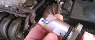
You can adjust the Solex starting system both on an installed carburetor and on a dismantled one. In the first case, the adjustment comes down to determining the number of crankshaft revolutions, but with the carburetor removed, it is possible to adjust the starting system due to the gaps at the edge of the dampers. On the engine power system device removed from the vehicle, adjust the gap between the damper and the chamber wall - the gap should be 1.1 mm. Adjustment work is carried out using a wrench or screwdriver.
More experienced and advanced car owners prefer to adjust the Solex by determining and setting the crankshaft speed. This method is faster, but also requires certain specific knowledge. This technique consists of the following:
- Air filters are dismantled;
- The choke is disconnected, the engine starts;
- Using available tools, the air damper is opened by a third;
- The lever sets 3200 rpm of the crankshaft;
- The air damper should be closed, loosen the lock nut, and use the adjusting screw to reduce the rotation speed to 3000 rpm;
- Tighten the locknut.
Using a gas analyzer, you can also configure the starting system. The device measures the amount of carbon monoxide in gases. If the value is 8%, then there is no need to configure the launch system. If the value is below 8%, then the screw on the diaphragm mechanism cover should be tightened, and if the value is higher than normal, the screw should be loosened and the measurement taken again.
Adjusting idle speed
This procedure is necessary to ensure that the power unit operates stably and that the exhaust gases contain as few harmful substances as possible. In the garage, using your own efforts, all the work can be done using a tachometer. The motor is first brought to operating temperature, after which the adjustment itself is carried out directly. Using the mixture quantity screw, the crankshaft rotation speed is set at 850-900 rpm, after which the quality screw is tightened with a screwdriver until the speed is set at around 800 rpm. A similar procedure must be carried out several times until the engine begins to operate stably, and a minimum amount of vacuum in the tube is observed.
Correct tuning of Solex will allow the car owner to enjoy high-quality, and most importantly, trouble-free engine operation. Experts recommend adjusting the idle speed twice a year. Thus, it is possible to achieve significant fuel savings and the emission of a minimum amount of harmful substances into the atmosphere, plus, a properly adjusted mechanism of the engine power system will significantly save personal funds on the services of service stations.
Video: VAZ 2121 NIVA Valve adjustment
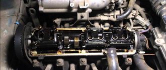
In order to measure the thermal clearances of valves on Niva 2121, you must perform the following procedure:
- Remove the cylinder head cover.
- We turn the crankshaft as it rotates until the marks on the camshaft drive sprocket and the bearing housing align.
- In this case, the mark on the crankshaft pulley should be located opposite the long mark located on the timing cover. Which corresponds to the position of the top dead center in the fourth cylinder (end of the compression stroke) - it is necessary to adjust the inlet valve of the 3rd cylinder and the exhaust valve of the 4th, that is, the 6th and 8th cams. The report is from the camshaft sprocket.
| Crankshaft rotation angle, degrees | No. of adjustable valves (cams) |
| 0 | 8 and 6 |
| 180 | 4 and 7 |
| 360 | 1 and 3 |
| 540 | 5 and 2 |
We rotate the crankshaft 180°, which also corresponds to moving the ignition distributor slider 90°, and adjust the next pair indicated in the table above.
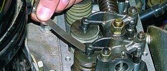
To check and adjust the gaps, do the following:
- Insert the required feeler gauge into the gap between the valve lever and the camshaft cam. The probe should move with little effort. If it does not fit, or moves too freely, we make an adjustment.
- Use a seventeen-size open-end wrench to loosen the locknut, and use a thirteen-size wrench to turn the adjusting bolt and achieve the required clearance. When tightening the lock nut, the gap may become slightly off, so it is worth checking it again.
- After carrying out a full adjustment cycle, turning the crankshaft again, we check and, if necessary, adjust the clearance to the desired level.
Carburetor Niva 21213: diagram, adjustment, tuning, repair
Niva carburetor: we set up and repair it ourselves
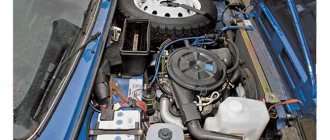
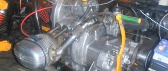
The carburetor on models 2121, 21213 and other cars has basically the same device. Functionally, it is located in the propulsion system, and with its help the fuel is mixed to the state of a combustible mixture. A carburetor, as a rule, consists of several main elements - a float chamber, a so-called jet (with a spray), a diffuser, and a throttle valve. It can have from one to four cameras on different cars, sequential or simultaneous opening of the throttle valves, horizontal, downward or upward movement of the working mixture.
Stages of adjusting the VAZ 21213 carburetor
Improper carburetor operation is the cause of many engine malfunctions. If fuel consumption has increased, there are unstable idle speeds, the engine does not start even when hot, or it starts and immediately stalls - the problem is 100% in the carburetor. In most cases, there is no need to remove it and install a new one - just clean it and make adjustments.
What does carburetor adjustment include?
Adjusting the carburetor on Niva 21213 will allow you to achieve stable operation of this unit even at low speeds, when the crankshaft rotates at a minimum frequency.
As a rule, such work includes adjusting the starting system, idle speed, and the fuel level in the float chamber.
Before you begin the adjustment, you should prepare for this process. You will need a tachometer or multimeter with the appropriate mode, as well as a slotted screwdriver with a width of 3 mm.
Adjusting the VAZ 21213 carburetor is carried out in several stages:
- If the engine is cold, it is necessary to warm it up - the temperature should be at least 85 degrees;
- You need to fully open the carburetor air damper - to do this, press the damper drive handle, which is also called the “choke”, all the way.
- Connect the tachometer to the stopped engine according to the following diagram: “minus” - to ground, “plus” - to terminal “K” on the ignition coil;
- After connecting the device, start the engine, turn on the heater and headlights;
- Take a screwdriver and, by adjusting the fuel mixture supply screw, ensure that the engine runs stably at idle speed. You can do this by ear, but it is better to use a tachometer that is connected to the engine. For a Solex carburetor, 750-800 rpm is optimal;
- Unscrew the screw with a screwdriver until the speed rises to 900, and then tighten it again to 800 rpm.
If adjusting the carburetor on Niva 21213 did not help achieve the desired results, then you will have to remove it and disassemble it, thoroughly cleaning all the parts.
Engine Repair Tags: VAZ 21213
Adjusting the valves of Niva, Chevrolet Niva and classics
The topic of the article is installing a set of death hydraulics and adjusting the valves of Niva, Chevrolet Niva and classics. The previous series talked about the kit itself; this chapter will focus on installing it and adjusting the valves. I would like to thank two people who helped me finalize this article. Seryoga Urashin (Leningrad) and Denis Kosachev (Ryazan).
The horrors of our town
I was prompted to write a separate article by several letters. The essence of which was as follows. We understand that switching to bolts is good, but we don’t have people left who can adjust the valves properly. The nightmare is that this applies to cities with millions of people, where everyone has switched to foreign cars. But in small towns, people still remember how it’s done. I will try to write down step-by-step instructions with pictures and I hope that for someone it will help get rid of wetsuits.
Installation
After removing the hydraulics, carefully remove any remaining oil and coke from the wells. Degrease the internal threads with something decent (gasoline, acetone, white spirit). Mount the screws into the cylinder head (tightening torque is about 7-8 kg). We kindly request. Technologies do not stand still. Use a medium-strength thread locker for this operation. The price list includes a product that I use during assembly, manufactured by Febi (Germany). There is nothing more disgusting than the moment when you start the operation - “adjusting the field valves”, and suddenly you see that the screw is rotating along with the lock nut. I'll tell you a secret, everything will have to be disassembled and reassembled)). After this operation, I recommend taking a short break; there will be enough time for lunch for the thread locker to polymerize. After this you can install everything else. Don't forget a few drops of motor oil or mounting paste on the working surface of the rocker and the soldier's ball.
Adjusting the Niva valves, process
zero position and offset mark
- The first task is to label everything. I will not describe this procedure. I will only say one thing: if you couldn’t do this or have no idea what it is, you definitely don’t need to climb any further. Don't be upset if the mark on the camshaft gear doesn't hit the center. This only happens in AvtoTAZ books and manuals. Or half a tooth forward or half a tooth back. Mark for mark, this is rather an exception to the rule. The photo shows very clearly that there is a clear vertical line on the gear and a dot that corresponds to the mark on the gear on the other side. Be careful with the mark on the camshaft. This is a small dot on the back of the gear near the teeth. When everything is according to the marks, we will call this position ZERO.
- Adjustment of valves. This operation can be complete, or it can be simplified. It all depends on the camshaft you installed. Why do I recommend starting with the 21213 camshaft in almost all articles? Because it can be adjusted simply and quickly in two steps. So, everything is on the marks, in the zero position. We adjust 8, 7, 6, 4 valves. Working tools, open-end wrenches 17 and 13 mm. Using a ratchet wrench, turn the crankshaft clockwise once until the mark on the crankshaft pulley matches. That is, we make a full turn, 360 degrees. We do not pay attention to the distribution mark; it will be vertically below. We adjust 1, 2, 3, 5 valves. Voila, the process is complete. This adjustment is only possible on full-base shafts.
- Fully adjustable. We wanted to install an Estonian shaft, the shaft is not full, and simple adjustment does not work here. We set the timing belt to the zero position and make a vertical line on the camshaft gear (I use an oil marker). We adjust valves 8 and 6. We turn the engine by the crankshaft so that our line points to “three o’clock”, this is the first position. We adjust valves 7 and 4. Turn it further, the dash is at “six o’clock”. We adjust valves 1 and 3. And finally, turn it one more time, the dash at 9 o’clock, 5 and 2 valve. The process is over.
Tool
probe 0.15 mm
There are two ways to adjust according to the type of tool. By probes and by a dial indicator. For semi-professional use, the first option is suitable. The Fiat manual recommended the following clearances at an engine temperature of 20 degrees (that is, normal). Intake valves 0.15 mm. Graduation is slightly more than 0.17-0.20 mm. My personal opinion after 20 years of practice is the following. The set gap very much depends on the manufacturer and valve material . If this is a valve of average quality, then the gaps can be made according to the manual. If there are Kolbenschmidt valves on both the inlet and outlet, then you can do 0.15 in a circle. Now on to the probes. Of course, everything is determined by the word experience, and the first two or three times you can adjust this... “what you can’t say in a fairy tale, you can’t describe with a pen.” Therefore, I remembered one wonderful thing for mechanics, turners and milling operators, which was made in the USSR, for technical control. It was called a plug gauge. That is, it is a calibrated tool, with two “tails”, one passable, the other non-passable. By analogy with this miracle, I offer two tools. The first is a 0.15 mm gap adjustment gauge and a set of gauges that contains a 0.2 mm gauge. Now all the “miracles” of adjustment come down to a simple thing. One should get through, the other shouldn't. This way we get into the required tolerance range.
set of probes, “fan”
Question answer
How often are the Niva valves adjusted? I recommend carrying out the second adjustment, which I call final, after 500-700 km, after installing the kit and the first adjustment. As a rule, 2-3 valves “run away”. According to Soviet books and training manuals, it was recommended to CHECK the gaps once every 12-20 thousand km, that is, about once a year. Operational practice has shown that engines run without adjustment for 50 and 80 thousand km. Therefore, the following recommendation is factual.
A series of articles devoted to hydraulic compensators and bolts:
Part 1. Hydraulic compensators, review article
Part 2. New type hydraulic compensators
Part 3. Replacing hydraulic compensators with bolts. Set “death to hydrikas”
Part 4. Installing the “death to hydraulics” kit and adjusting the gaps
Did you like the article? Share with your friends!
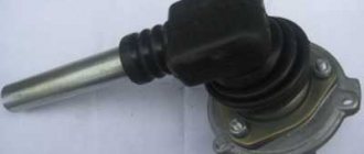
Adjusting the carburetor drive
Performed when replacing the carburetor, as well as when drive parts are worn or replaced
When the gas pedal is fully pressed, the throttle valves should be fully open, and when released, they should be closed.
If this is not the case, disconnect the end of the drive's longitudinal rod from the bracket on the valve cover (see Removing the carburetor from the engine).
Using an “8” wrench, loosen the lock nut of the tip (for clarity, we show the operation with the rod removed).
By unscrewing or twisting the tip, we achieve the correct adjustment.
We also check the distance between the centers of the transverse rod ends, which should be 80 mm.
If the adjustment range is not enough (the dampers do not open completely), bend the gas pedal up.
Adjusting the fuel level in the float chamber
Performed when replacing a needle valve or float. Remove the carburetor cover (see Disassembling the carburetor).
Having placed the carburetor cover horizontally with the floats up, we use a caliper to measure the distance from the cover gasket to the farthest point of each float.
It should be between 34–35 mm for both floats.
The gap is adjusted by bending the tongue or float arms
The bearing surface of the tongue must be perpendicular to the axis of the needle valve and must not have any dents or nicks.
When installing the cover in place, check whether the floats are touching the walls of the float chamber; if necessary, bend the float arms.
How to adjust valve clearances on a Niva 2121 with your own hands - step-by-step instructions
And so, now let's move on to step-by-step instructions for adjusting valve clearances on Niva 2121:
- Remove the cylinder head cover.
- We turn the crankshaft as it rotates until the marks on the camshaft drive sprocket and the bearing housing align.
- In this case, the mark on the crankshaft pulley should be located opposite the long mark located on the timing cover. Which corresponds to the position of the top dead center in the fourth cylinder (end of the compression stroke) - it is necessary to adjust the inlet valve of the 3rd cylinder and the exhaust valve of the 4th, that is, the 6th and 8th cams. The report is from the camshaft sprocket.
- Crankshaft rotation angle, degrees No. of adjustable valves
- We rotate the crankshaft 180°, which also corresponds to moving the ignition distributor slider 90°, and adjust the next pair indicated in the table above.
- To check and adjust the gaps, do the following:
- Insert the required feeler gauge into the gap between the valve lever and the camshaft cam. The probe should move with little effort. If it does not fit, or moves too freely, we make an adjustment.
- Use a seventeen-size open-end wrench to loosen the locknut, and use a thirteen-size wrench to turn the adjusting bolt and achieve the required clearance. When tightening the lock nut, the gap may become slightly off, so it is worth checking it again.
- After carrying out a full adjustment cycle, turning the crankshaft again, we check and, if necessary, adjust the clearance to the desired level.
- Remove the cylinder head cover.
- We turn the crankshaft as it rotates until the marks on the camshaft drive sprocket and the bearing housing align.
- In this case, the mark on the crankshaft pulley should be located opposite the long mark located on the timing cover. Which corresponds to the position of the top dead center in the fourth cylinder (end of the compression stroke) - it is necessary to adjust the inlet valve of the 3rd cylinder and the exhaust valve of the 4th, that is, the 6th and 8th cams. The report is from the camshaft sprocket.
- Angle of rotation of the crankshaft, degrees No. of adjustable valves (cams)
- We rotate the crankshaft 180°, which also corresponds to moving the ignition distributor slider 90°, and adjust the next pair indicated in the table above.
- To check and adjust the gaps, do the following:
- Insert the required feeler gauge into the gap between the valve lever and the camshaft cam. The probe should move with little effort. If it does not fit, or moves too freely, we make an adjustment.
- Use a seventeen-size open-end wrench to loosen the locknut, and use a thirteen-size wrench to turn the adjusting bolt and achieve the required clearance. When tightening the lock nut, the gap may become slightly off, so it is worth checking it again.
- After carrying out a full adjustment cycle, turning the crankshaft again, we check and, if necessary, adjust the clearance to the desired level.