Correctly pumping the brakes on a VAZ-2114: order and sequence of actions
If when you press the brake pedal it fails, and after several presses everything returns to normal, it means there is air in the system .
He needs to be kicked out, that is, pumped up. On the VAZ-2114 hatchback, you need to pump the brakes “diagonally”: start from the rear left wheel, move to the front right, etc. Also, if the rear axle is suspended, then install a screwdriver between the pressure regulator and the bracket. We study the design of the brake system - watch the video.
Examination
The operation of the VAZ-2109, 2110 and other AvtoVAZ models is checked on the move, in closed areas. To do this, accelerate the car to a speed of 40 km/h and sharply press the brake. The rear wheels should lock 1/2 second later than the front wheels.
The wheels are monitored by an assistant located outside the car. If wheel locking occurs noticeably later or does not occur at all, and also if the rear axle is locked simultaneously with the front, the sorcerer adjustment procedure is repeated.
To increase the response time of the rear brakes, the gap between the adjuster and the bracket is increased; to shorten it, it is reduced accordingly.
Source: znanieavto.ru
Preparation for work
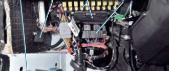
First of all, disconnect the sensor connector and secure this connector next to the tank. Then open the lid and add liquid to the MAX mark. This requires DOT-4 fluid .
Level sensor connector
On any car, including the VAZ-2114, the brakes are pumped with the lid closed. This means we tighten the lid harder, and then roll the car onto an overpass or pit.
If a lift is used, it means that when bleeding the rear cylinders, a spline is placed in the regulator (sorcerer).
Pressure regulator (sorcerer)
The screwdriver here is between the bracket and the rod. When bleeding the front brakes, remove the screwdriver.
Safety precautions: the handbrake must be engaged and the ignition key must be removed.
Video: VAZ 2114 sensors - what they are and what they do
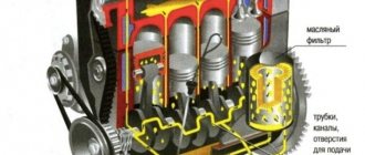
Signaling devices called sensors are installed in order to inform the driver or some control device about changes occurring during the operation of the car or about the state of the corresponding unit or system, as well as to signal in case of failures or emergency conditions in the car. Therefore, the driver must have a good understanding of the operating principle and location of the sensors on the VAZ 2114.
- The oil level has dropped significantly;
- the oil filter is clogged;
- the oil pump has failed;
- oil pressure sensor is faulty;
- The wiring is faulty or the oil pressure has dropped due to leaks.
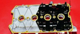
On an eight-valve engine, the sensor is located on the right side below the valve cover in the cylinder head. On a sixteen-valve engine - on the left end of the camshaft bearing housing.
Where is the coolant temperature sensor located on the VAZ 2114
For proper operation, ensuring the collection and transmission of optimally accurate indicators, the DTOZH must be located in direct contact with the measured medium, that is, it must be immersed in the coolant.
Let's look at a temperature sensor using the example of one of the cars in the Lada model range.
The cooling system of VAZ cars is a complex of the following parts:
- heating and cooling radiators;
- fan;
- pump;
- expansion tank;
- coolant temperature sensor.
The measuring device, located between the thermostat and the cylinder head, consists of a resistor and is connected to the control unit by two wires.
Determination of the heating level is based on the resistance value, which increases or decreases depending on the coolant temperature.
Important! The temperature detector on the VAZ 2114 is not located on the radiator, which is typical for other VAZ models, but on the engine block.
Where is the idle speed sensor located on the VAZ 2114
Many drivers and mechanics who are or have been involved in repairing this device know where the sensor is located and note its extremely inconvenient location. IAC VAZ 2114 is destined for a place of permanent registration on the body of the throttle device.
Therefore, you will have to put up with some inconveniences while working with it.
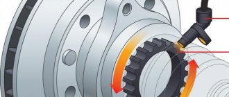
Where is the crankshaft sensor located on the VAZ 2114
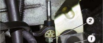
It is not difficult to detect the shaft position sensor on a VAZ 2114. It is located under the hood near the crankshaft pulley and is attached to the oil pump with a bolt.
Sequence and correct procedure for pumping brakes on a VAZ-2114
- We find a fitting on the rear wheel drum (photo 1). It is usually closed with a cap that is removed. Place a hose on the fitting.
Rear brake cylinders
Bleeding the front cylinders
Possible sequence for pumping brakes for a VAZ-2114: rear right wheel, front left, rear left, etc. Each circuit is pumped starting from the rear wheel.
Articles
- 2101-1602591 – rear cylinder fitting;
- 2101-1602591-01 – disc brake fitting;
- 2101-1602592 – fitting cap.
How to bleed the brakes alone?
It seems that one person can bleed the brakes. But then you need to increase the pressure in the tank. The source of air will be the tires. By the way, the limiting value should be considered 2 atmospheres.
The cap with the nipple is screwed onto the neck of the tank. Next, the “extension cord” is assembled. The donor wheel is hung out when bleeding the brakes.
You can open the fittings one by one and drain the liquid. But you also need to monitor the fluid level in the tank.
Topping up is done as follows: disconnect the “extension cord” from the tire, unscrew the cap, etc.
What does the VAZ 2114 brake system consist of?
The brakes of the VAZ 2114 are a vital system of the car. These are not loud words and every driver will agree with this. Also, every driver knows that timely, high-quality repair of the VAZ 2114 brake system is the key to its trouble-free operation.
The brake system on the VAZ 2114 consists of two main parts:
- Wheel mechanisms - directly affect the elements rotating with the wheel and slow down its rotation.
- Drive – a system for transmitting force from the pressed pedal to the wheel mechanisms.
The “fourteenth” has a dual-circuit system with a hydraulic drive. This means that the force created by pressing the pedal creates fluid pressure (hydraulics) throughout the system. This same pressure forces the wheel cylinders to work. The concept of “dual-circuit” means that the pedal force is transmitted along two lines (circuits) independent of each other to pairs of wheels. The contours have a diagonal distribution: the rear right wheel works together with the front left one, and the rear left one works with the front right wheel. If one of the circuits fails, this solution allows you to maintain vehicle stability when braking, especially on slippery roads and when turning.
Important: the main condition for the system to work is its tightness. Therefore, it is extremely dangerous to operate a car with fluid leakage. It is also extremely dangerous for air to enter the system. According to its physical properties, air, when compressed, decreases in volume many times over, unlike liquid, which, when compressed, practically does not change its volume. When braking a car with a leaky system, the pedal may “fail” and the brakes of the VAZ 2114 will not work.
VAZ 2114 brake system diagram
The brake system diagram of the VAZ 2114 has a classic layout, similar to both VAZ models and cars of many world brands.
- Master brake cylinder.
- Metal pipes of the 1st circuit.
- Flexible hose for front mechanisms.
- Liquid reservoir.
- Vacuum brake booster.
- Metal pipes of the 2nd circuit.
- Rear wheel cylinders.
- Brake pressure regulator drive lever.
- Flexible hose for rear mechanisms.
- Pressure regulator.
- Pressure regulator bracket.
- Pedal.
Main brake cylinder VAZ 2114
General view of the brake master cylinder (MBC) under the hood of a car with a fluid reservoir and a vacuum booster.
The master brake cylinder creates pressure in the system, distributes it along the circuits and transmits it to the wheel cylinders. It consists of a two-section housing, inside which a piston moves, driven by a pedal. The fluid pressure created in the hydraulic structure is transmitted through circuits to the wheel mechanisms.
The vacuum booster reduces the force applied to the pedal. This makes the system more efficient. The operation of the vacuum valve directly depends on the operation of the engine. The vacuum booster is connected to the engine intake manifold by a flexible rubber hose. The vacuum (vacuum) in the amplifier is created by creating low pressure in the intake manifold from the movement of the engine pistons during the intake stroke.
Instructions for the last chapter in one video
Yes, as on most cars, bleeding is done crosswise, but I would advise changing the old brake hoses, pads and brake fluid for a brake system that does not fail. It’s better to spend money once and forget about the brakes than to constantly crawl under the car.
Pumping is not difficult, call an assistant and pump them according to the instructions in the manual. Just keep an eye on the brake fluid level when bleeding. After bleeding, drive off with caution. Until the pedal becomes hard and the pads are in place.
Design
The task of the driver and car owner part-time is to constantly monitor the condition of the brake system.
Failure of one of its elements can lead to serious consequences. Therefore, you should know what exactly is included in the braking system.
The components of the vehicle are:
- Brake fluid reservoir mounted on the GTZ;
- Metal pipelines of two circuits;
- Flexible brake hoses for front and rear wheels;
- GTZ (brake master cylinder located in the engine compartment);
- Brake cylinders of front and rear wheels;
- Pressure regulator;
- Brake fluid level sensor;
- Vacuum booster.
Tank with fuel fluid
According to the recommendations of experts, replacement of fuel fluid is carried out once every 3 years, but at least once every 45 thousand kilometers.
List of devices
Sensors are needed to report on the performance of systems, signal the level of cooling liquids and oil, and prevent or anticipate emergency situations.
These small devices, despite their size, play an incredible role in the performance of the machine. Therefore, it will not be superfluous to know which sensors are on your car.
Let us list the main ones present in the VAZ 2114 systems. We include sensors in this list:
Coolant temperature;
Coolant level in the expansion tank;
Mass air flow rate indicator;
Engine idling;
Brake fluid level in the system;
Camshaft position (it is called a phase sensor);
Outside air temperature;
Uneven road surface.
This list is very, very extensive. But even this, the owners of the VAZ 2114 do not want to stop, which is why they are introducing several more different sensors into the system:
- Light devices;
- Reverse;
- A device that signals open doors;
- Brake pad wear indicator, etc.
Reasons for replacement
There are several characteristic malfunctions that must necessarily entail the replacement of the TJ.
- The presence of leaks from the brake cylinders, which lead to the loss of a large amount of fluid.
- The appearance of air pockets in the pipeline and hose system. They arise due to a leak in the brake system elements.
- Scuffs or deformation of flexible hoses installed on wheels. They also require replacement of the hoses themselves.
- Violation of the integrity of the sealing rings in the main brake cylinder, which leads to leakage of the working substance.
- Fluid leaking through the sealing ring of the pusher on the rear wheels.
- Violation of the tightness of the system circuit. This can be felt by a partially collapsed brake pedal.
- Mechanical failure of one of the elements of the braking system. In addition to repairing or replacing them, you will definitely have to change the TZ.
Choice of TZ
To choose the best option for a brake substance, you should take into account the main parameters of its selection so that it meets the requirements of the VAZ 2114 model. After all, this is the car we are talking about.
Index
Requirement
It must be high so that steam bubbles do not form inside the system and block the flow of liquid
Good viscosity ensures efficient pumping of fluid through the system
This criterion is responsible for the ability of a substance to absorb water
The thermal fluid should not only promote braking, but also prevent overheating of the internal surfaces due to the lubricating effect
Neutral to rubber
The composition should not have a destructive effect on the rubber elements used in the system
Corrosion resistance
The liquid should protect metal elements from corrosion and rust.
You should choose the DOT 3 marking
Having chosen the vehicle that is suitable for your car, you should replace it. It’s entirely possible to do the work yourself, but you should first read the instruction manual, consult with specialists, or watch visual video lessons.
Draining and bleeding process
Replacement
To replace the TJ yourself, you will need a certain set of tools and materials. This set includes:
- Brake fluid - 500 millimeters;
- A set of keys;
- Screwdriver Set;
- Transparent flexible hose;
- Container for draining old fluid;
- Dry rags for cleaning surfaces.
To work, you will definitely need the help of one more person, so when pumping, one should be inside the car, and the other outside.
Let's start the procedure.
- Unscrew the cap on the master cylinder reservoir and place it on a prepared surface. The cover is combined with the float of the fuel oil level sensor, so be careful, because a toxic and dangerous substance will remain on it.
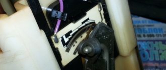
- Unlock the rear brakes using a screwdriver. It is simply inserted between the plate and the piston. Ready.
Inserted a screwdriver
- Clean the right rear brake release valve of any accumulated dirt and dust, then remove the rubber cap that covers the valve.
- Place a flexible transparent hose onto the valve fitting and place its other end in a container to drain the liquid.
- Approximately once every two seconds, press the gas pedal all the way four times in succession. When you press the fifth time, lock the pedal in the clamped position.
- Unscrew the valve at least half a turn. As the brake fluid drains, the pedal will gradually begin to sink.
- As soon as the fluid flow stops, close the valve.
- Simultaneously with the procedure, do not forget to monitor the level of fuel fluid in the tank.
- As you pump out the old substance, add a little new one. This will avoid the formation of air locks inside the system.
- Add fresh fuel fluid into the tank until all the old fluid comes out and new clean substance begins to flow through the hose into the container.
- Having completed the work on the rear right wheel, go to the front left and perform a similar procedure. Due to this movement pattern, you will be able to completely get rid of the old fuel oil in one circuit.
- By analogy, remove the fuel fluid from the second circuit in the same sequence. Having completed draining, close the valves with caps and add new fuel fluid to the required level.
Accuracy comes first
After completing the replacement procedure, you should definitely bleed the brakes. It is strictly not recommended to go out on the road without it, since the brakes may simply not work.
Why bleed the brakes?
Bleeding a vehicle is a preventive measure aimed at ensuring stable operation of the brakes. The point is to remove foreign liquid and excess air.
Air and excess liquid can appear in the system for various reasons. Namely:
- The hoses are damaged and their integrity is compromised;
- Low-quality brake substance is used;
- System elements were replaced or brake fluid was updated;
- The seal of the vehicle is broken.
Leveling up
In fact, you can bleed the brakes on your own, and sometimes there is even no other way out. First, we recommend watching a training video in which you will be able to clearly study all the nuances of the procedure.
Important rule. Do not add new fuel fluid to the system if it does not match the composition of the old substance.
Make sure that everything is good with the vehicle’s tightness, so that the work is not done in vain.
If you have just finished replacing your vehicle, do not rush to let your friend go home. You will also need it at the pumping stage.
Press the pedal to the floor
The brakes need to be bled in a certain sequence:
- Right rear brake.
- Left front brake.
- Left back.
- Right front.
We begin the pumping procedure.
- Check the brake fluid level in the reservoir. Before pumping, it must be as full as possible;
- Clean the outlet valve from any contaminants present there;
- Remove the protective cap from the valve, and before that fill the glass container with the working substance - TJ;
- Take a rubber hose and place it on the valve head;
- Place the other end in a container with TJ. This is a homemade device for pumping, which is not inferior in efficiency to professional equipment at car service stations;
- Approximately five times with a break of 2 seconds, press the brake pedal all the way;
- After making the last press, lock the pedal to the floor;
- Unscrew the valve 75 percent;
- Liquid with bubbles will begin to flow from there;
- As soon as the flow stops, you can close the valve;
- After closing the valve, release the pedal;
- Repeat steps 5-7 at least one more time. More bleeding cycles may be required. Your task is to ensure that there are no air bubbles when the liquid flows out;
- As the fuel fluid flows out, be sure to add it to the tank, maintaining it at the maximum level;
- Having completed pumping, remove the hose, remove all traces of fuel fluid from the fitting and screw on the cap.
Despite the abundance of stages, in practice the work does not take much time. But by replacing and pumping the vehicle yourself, you can significantly save on car service costs.
Brake pressure regulator device for VAZ 2114, VAZ 2115, VAZ 2113, Lada Samara 2
It regulates the pressure in the hydraulic drive of the brake mechanisms of the rear wheels depending on the load on the rear axle of the VAZ 2113, VAZ 2114, VAZ 2115. It is included in both circuits of the brake system and through it the brake fluid flows to both rear brake mechanisms.
Pressure regulator drive: 1 – pressure regulator; 2, 16 – pressure regulator mounting bolts; 3 – bracket for the pressure regulator drive lever; 4 – pin; 5 – pressure regulator drive lever; 6 – axis of the pressure regulator drive lever; 7 – lever spring; 8 – body bracket; 9 – pressure regulator mounting bracket; 10 – elastic lever of the pressure regulator drive; 11 – earring; 12 – earring bracket; 13 – washer; 14 – retaining ring; 15 – bracket finger; A, B, C - holes
The pressure regulator of the VAZ 2114, VAZ 2115, VAZ 2113 is attached to bracket 9 with two bolts 2 and 16. In this case, the front bolt 2 simultaneously secures the fork bracket 3 of the lever 5 of the pressure regulator drive. A double-arm lever 5 is hinged on the pin of this bracket with a pin 4. Its upper arm is connected to an elastic lever 10, the other end of which is pivotally connected to the rear suspension arm bracket through an earring 11. Bracket 3 together with lever 5 can be moved relative to the pressure regulator due to the oval holes for the fastening bolt. This regulates the force with which lever 5 acts on the regulator piston (see chapter “Adjusting the VAZ 2113 pressure regulator drive”).
Pressure regulator: 1 – pressure regulator housing; 2 – piston; 3 – protective cap; 4, 8 – retaining rings; 5 – piston sleeve; 6 – piston spring; 7 – body bushing; 9, 22 – support washers; 10 – sealing rings of the pusher; 11 – support plate; 12 – pusher bushing spring; 13 – valve seat sealing ring; 14 – valve seat; 15 – sealing gasket; 16 – plug; 17 – valve spring; 18 – valve; 19 – pusher bushing; 20 – pusher; 21 – piston head seal; 23 – piston rod seal; 24 – plug; A, D - chambers connected to the main cylinder; B, C - chambers connected to the wheel cylinders of the rear brakes; K, M, N - gaps
The Lada Samara 2 regulator has four chambers: A and D are connected to the main cylinder, B – to the right, and C – to the left wheel cylinders of the rear brakes of the Lada Samara 2. In the initial position of the brake pedal, piston 2 is pressed by lever 5 through a plate spring 7 k pusher 20, which under this force is pressed against the seat 14 of the valve 18. In this case, the valve 18 is pressed away from the seat and a gap H is formed, as well as a gap K between the piston head and the seal 21. Through these gaps, chambers A and D communicate with chambers B and C When you press the brake pedal, fluid through gaps K and H and chambers B and C enters the wheel cylinders of the brake mechanisms of the VAZ 2115. As the fluid pressure increases, the force on the piston increases, tending to push it out of the body. When the force from the liquid pressure exceeds the force from the elastic lever, the piston begins to move out of the body, and after it, under the action of springs 12 and 17, the pusher 20 moves together with the sleeve 19 and rings 10. In this case, the gap M increases, and the gaps H and K decrease . When the gap H is completely selected and the valve 18 isolates chamber D from chamber C, the pusher 20, together with the parts located on it, stops moving after the piston. Now the pressure in chamber C will vary depending on the pressure in chamber B. With a further increase in the force on the brake pedal, the pressure in chambers D, B and A increases, piston 2 continues to move out of the body, and sleeve 19 together with o-rings 10 and plate 11 under increasing pressure in chamber B, it moves towards plug 16. At the same time, the gap M begins to decrease. Due to the decrease in the volume of chamber C, the pressure in it, and therefore in the brake drive, increases and will be practically equal to the pressure in chamber B. When the gap K becomes zero, the pressure in chamber B, and therefore in chamber C, will increase to a lesser extent degree than the pressure in chamber A due to throttling of the liquid between the piston head and seal 21. The relationship between the pressure in chambers B and A is determined by the ratio of the difference in the areas of the head and piston rod to the area of the head. As the vehicle load increases, the elastic lever 10 is loaded more and the force from lever 5 on the piston increases, that is, the moment of contact between the piston head and seal 21 (see Fig. 6.4) is achieved at greater pressure in the master cylinder. Thus, the effectiveness of the rear brakes increases with increasing load. If the brake circuit “right front - left rear brake VAZ 2114” fails, the sealing rings 10, bushing 19, under the pressure of the liquid in chamber B, will move towards the plug 16 until the plate 11 stops in the seat 14. The pressure in the rear brake will be regulated by the part of the regulator, which includes it includes piston 2 with seal 21 and bushing 7. The operation of this part of the regulator, in the event of failure of the said circuit, is similar to the operation with a working system. The nature of the change in pressure at the outlet of the regulator is the same as with a working system. If the brake circuit “left front - right rear brake” fails, the pressure of the brake fluid forces the pusher 20 with the bushing 19 and sealing rings 10 towards the piston, pushing it out of the housing. The M gap increases and the H gap decreases. When valve 18 touches seat 14, the increase in pressure in chamber C stops, that is, the regulator in this case works as a pressure limiter. However, the achieved pressure is sufficient for reliable operation of the rear brake. There is a hole in housing 1, closed by plug 24. Liquid leakage from under the plug when it is squeezed out indicates a leak in rings 10.
Where did the air come from?
Air in the brake system may appear for the following reasons:
- Got in while changing brake fluid (How to change brake fluid?).
- Got it when replacing any brake elements, for example when replacing a brake cylinder (How to replace a rear brake cylinder?).
- Air may also appear due to a leak in the brake system, for example, cracked brake fluid pipes that need to be replaced immediately.
- The rear brake cylinder is leaking.
- The front brake cylinder is leaking.
- A leaky GTZ (brake master cylinder) can also be a problem.
Important: Over time, water gets into the brake fluid, as evidenced by its darkening. In this case, you need to replace the brake fluid. And in general, it is recommended every three years or 45 thousand km. mileage, change the brake fluid, because One way or another, condensation accumulates in it.
Also, prevent brake fluid from getting on the car body, otherwise it will easily wash away the paint to bare metal.
How to bleed the brake system?
Before you start bleeding the brakes, eliminate the cause of the problem.
To bleed the brakes you will need:
- assistant;
- empty plastic bottle;
- new brake fluid "Rosa" or another that is already in use
- special wrench or regular socket wrench “8”;
- hose or vinyl tube of suitable size;
- overpass, inspection hole or jack.
If the rear wheels are suspended, then before bleeding it is necessary to unlock the rear brake pressure regulator (sorcerer) by slipping a screwdriver or washer of a suitable size (see photo).
The brakes need to be pumped diagonally, starting with the one farthest from the master cylinder.
First of all, we bleed the rear right wheel, then the front left one; rear left and front right.
- Open the hood and open the brake fluid reservoir cap.
- If necessary, top up to the MAX mark.
- Next, remove the rubber cap of the rear right wheel bleeder fitting, throw on a spanner or special wrench, tightly put the tube on top and lower the other end into a bottle with already filled liquid so that air does not re-enter the brake system.
- The assistant gets into the car and begins to pump (press) the brake pedal 7-8 times, the last time he pushes it to the floor and holds it.
- In the meantime, you should loosen the fitting about half a turn and brake fluid should come out. Meanwhile, the assistant keeps the pedal pressed and does not release it.
- As soon as the liquid stops flowing into the bottle, the fitting should be screwed back on.
- Next, we repeat the operation of steps 4,5,6 until liquid with bubbles stops flowing into the bottle. By the way, don’t forget to monitor the brake fluid level.
- After the last pumping, finally tighten the fitting and tighten the rubber cap.
- Then we repeat the same with other wheels, not forgetting the diagonal rule: front left, rear left, front right wheel.
- After bleeding the brakes, press the brake pedal and check the progress: if the pedal is soft and falls below its normal operating condition, then you should pay attention to the tightness of the brake elements of the system.
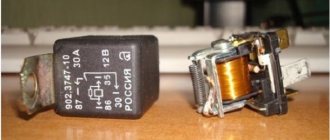
Error P0504 - the cause is the brake pedal position sensor
Owners of LADA cars with an electronic gas pedal may encounter error P0504 (mismatch of brake pedal sensors). Along with it, malfunctions in the engine may appear (stalls, speed fluctuates, does not start, etc.). Most often the cause is the brake pedal position sensor (brake light sensor or frog).
The brake pedal position sensor and brake light switch are mounted in one housing. Most often, the cause of its malfunction is a broken spring. In this case, you can repair the sensor yourself by replacing the spring with a new one. Or replace the sensor with a new one.
How to properly bleed the brakes on a VAZ-2114
Most often, it is necessary to bleed the brakes in different cars, including the VAZ-2114, after the brake fluid has been replaced. Air can also get into the brake system when replacing any unit. If there is air, the system is unable to function normally. A sign of the presence of air in the system is the “pushing” of the pedal when you press it. Moreover, if you press the pedal several times in a row, it returns to its normal position. If you are faced with such a situation, you should find out how to properly bleed the brakes on a VAZ-2114. By following certain rules, you will be able to complete this procedure quickly and without any problems.
HOW TO CHECK
Turn on the ignition and press the brake pedal, the brake lights should light up. After releasing the pedal they should go out. If the lamps do not light up, check the brake pedal sensor and the voltage supply from the battery to the wiring harness block.
(Largus, Vesta, XRAY) Move the rod lock to the right position using a screwdriver. We check the brake pedal sensor using a multimeter in ohmmeter mode. Circuit 3-4 should be closed (resistance value is close to zero), and circuit 1-2 should be open (resistance should tend to infinity). After pressing the rod, circuit 3-4 should open, and circuit 1-2 should close. Before installation, move the rod to the left position.
(Priora, Kalina, Granta, Niva 4x4) Circuit 1-4 should be closed, and circuit 2-3 should be open. After pressing the rod, circuit 2-3 will close, and circuit 1-4 will open.
Thus, the cause of error P0504 may be:
- faulty sensor or its wiring
- Brake pedal sensor is not adjusted
- it is necessary to reprogram the ECM (there is instruction No. 46-15 on this subject for Lada Granta and Kalina 2 with automatic transmission, users of our website can download it)
Preparatory stage
If you decide to bleed the brakes yourself, it is important to know that when bleeding you must use the same brake fluid as the one in the system. No other liquid can be used. You must first check the tightness of the system. To level up you need one more person. You will also need a hose of a suitable diameter for the bleeder fitting, a glass or plastic container (transparent), a wrench and a rag for cleaning the caps.
It is very important to know in what order to remove air from the brake system. This procedure must be carried out diagonally, alternating the rear and front brakes:
- rear right;
- front left;
- rear left;
- front right.
Sequencing
First you need to open the hood of the car and open the cap of the brake fluid reservoir. Make sure it is filled to the maximum. If not, add to about. After this, follow the steps in the following sequence:
- On the rear right wheel, find the cap that covers the fitting. Remove the cap and clean it of dirt.
- Fill a clear glass or plastic container with brake fluid.
- Place one end of the hose onto the fitting and place the other end into a glass or transparent plastic bottle. The hose must be lowered into the liquid.
- Ask your partner to sit behind the wheel and gently press the brake pedal 7 times with breaks of 2 seconds. After this, he must press the pedal again and leave it in this position (pressed all the way).
- While an assistant holds the pedal, use a wrench to unscrew the fitting 2-3 turns.
After all these steps, you will see that brake fluid will flow into a transparent container through the hose. Watch how it drains.
There will be visible air bubbles in it that need to be removed. Drain the liquid until the bubbles disappear. Then screw the fitting back on. Only after this can your assistant release the pedal. When the liquid flows into the container, monitor its level in the tank. If necessary, add brake fluid. If during pumping it completely leaks out, you will have to start the whole procedure from the beginning.
Repeat similar steps for each wheel in the above sequence. This mechanism of action is suitable not only for the VAZ-2114, but also for models 2113, 2115.
Many car owners are wondering: is it possible to carry out pumping alone? Yes it is possible. Only in this case, the pressure should be produced not by pressing the pedal, but by using a powerful compressor for these purposes. It should create a pressure of 2 atmospheres.
Car owners have to carry out pumping in different situations. Air can enter when replacing copper pipes at the rear or other components of the brake system, when hoses are damaged, when replacing brake fluid, or if the seal in the unit is broken. Regardless of the reason, after air enters the GTZ (brake master cylinder), bleeding must be carried out. Otherwise, the brake simply will not work.