Hi all! In this text we will talk about such easy tuning of the intake system as installing a throttle valve of increased diameter: https://motorring.ru/product/89
What does this give us? It allows the engine to pass the greatest amount of air. And the easier it is for him to do this, the greater the output power will be. Let me remind you that the diameter of the stock damper on VAZ 2108-2115 cars is 46 mm. Accordingly, when installing a throttle with a diameter of 52-56 mm on a car, in theory, the power should increase, which we will check later.
What size should I install the damper then?
By installing a throttle with a diameter of 56 mm on the “stock” motor, we will give the motor the opportunity to process air even more easily, compared to 52 and 54 mm, and even more so 46 mm. After all, with the same pressure on the gas pedal, much more air enters through 56 mm than through 46. But comfort in the cabin will be lost, a jerk will appear at the bottom, and you will also need to work more carefully with the accelerator pedal. In general, without a habit, it will be difficult at first.
52 mm is “neither two nor one and a half”. The effect will be practically unnoticeable! Since the difference with the “stock” one is only 8 mm. Money down the drain, so to speak. It's best to set it to 54 mm, which is what I did. Some kind of golden mean. But this is all theory. Let's move on to practice.
Advantages and disadvantages of an electronic pedal
When this device was created, there was no talk about driver convenience. It simply made it possible to increase the environmental friendliness of the car and free up space from cables and other mechanics, which made it possible to simplify the design. But a lot of time has passed, and now the electronic version can be found in almost all cars. During this period, all the advantages and disadvantages were revealed.
- Environmental friendliness - electronic engine management reduces the amount of exhaust gases, as speed is strictly controlled.
- Smooth operation - the electronic control unit does not allow the engine speed to change too sharply.
- Greater efficiency - again, due to strict speed control, fuel consumption is reduced.
- Easy engine starting in any season. A “cold start” in winter is easy and simple, without manual shamanism with the throttle, which can end in flooding the spark plugs.
Read more: Exhaust sound after removing catalyst
But there are also disadvantages:
- Impossibility of repair. If any unit breaks down - the pedal itself, the ECU, or the damper control unit, the entire unit will have to be replaced.
- The delay in response is also an advantage. But some drivers don’t like the fact that some time passes from the moment they press the pedal until the speed increases. Although this doesn't bother most people. This problem is often solved simply by adjustment.
- Gentle pressure - almost no resistance is felt. Some people don’t like this, especially those who are used to “feeling the car.”
The disadvantages are not very significant. The most serious is the first, but we must take into account that in general this device is much more reliable than a mechanical one with a cable. Therefore, it breaks much less often.
Practice. Effect
Unfortunately, I myself forgot to measure the acceleration “before and after”. But on the well-known YouTube site I found a video of one guy who was just doing this procedure. At first he had a completely stock VAZ-2112 coupe. Acceleration from zero to 100 km/h was around 11.9 seconds. Then he installed a larger throttle (56mm) and it turned out that the acceleration from 0 to 100 took one second less than before, namely 10.9 seconds.
So, let's figure out what are the advantages of this tuning. Firstly, there are no difficulties during installation; it is installed in place of the standard one without any modifications. Secondly, the response to the gas pedal has become more responsive. Thirdly, low price. Fourthly, this tuning does not require any sports brains or tuning.
Disadvantages of a large throttle:
- I personally had troubles with XX (idling speed);
- twitching appeared at the “bottoms” (low revs);
- the car begins to respond more sharply to small movements of the accelerator pedal, as a result, comfort in the cabin disappears and fuel consumption increases.
Conclusion: this spare part is needed by those who “chase power.” Who cares about horses under the hood rather than comfort? Such tuning will not appeal to a careful driver who is used to driving quietly and calmly.
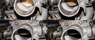
Gasoline is used as fuel in the internal combustion engines of VAZ-2109, VAZ-2110 and other models produced or produced by the Volzhsky Automobile Plant. However, in the cylinders it does not burn on its own, but in a mixture with air. The throttle valve is needed to prepare the air-fuel mixture in the required proportions. It is located behind the air filter in front of the intake manifold.
Basically, the throttle valve is an air valve that regulates the amount of air entering the engine. The principle of its operation is to change the cross-section of the air channel. When it is fully open, air flows freely into the intake manifold. To determine the opening angle, a throttle position sensor is used, which is connected to the engine control unit. Based on the signals transmitted by the sensor, the control unit issues a command to increase the amount of fuel injected, the working mixture is enriched, and the engine operates at maximum speed.
Throttle valve device
The design of the throttle body is not as simple as it might seem at first glance. Among other things, it is also part of the engine cooling system. It has channels for coolant circulation. It is also equipped with pipes, one of which is connected to the engine crankcase ventilation system, and the second to the gasoline vapor recovery system.
Idle speed control
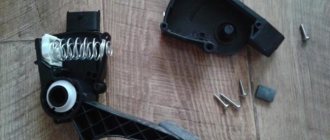
The idle air control is an electromechanical device whose task is to maintain a certain crankshaft speed when the throttle valve is fully closed. For example, while the engine is warming up or the load changes, when additional equipment is turned on. The design of the idle speed controller is as follows: inside the housing there is a stepper electric motor, to which a spring-loaded conical needle is connected. When the engine is idling, the needle, moving back and forth, adjusts the cross-sectional area of the bypass air channel through which air passes when the damper is fully closed.
The throttle valve can have two types of drive:
- mechanical, like VAZ-2109, VAZ-2110, VAZ-2114;
- electric, which is used on most modern cars.
Mechanical drive
For the VAZ-2109, VAZ-2110 and other outdated models of the Volzhsky Automobile Plant, the throttle valve is connected to the gas pedal via a steel cable. The mechanical drive has a very simple design and low cost, so it is still used on many inexpensive cars.
Electric
If the throttle valve is equipped with an electric drive, then there is no direct connection between it and the gas pedal. The principle of operation of an electric damper does not change, but its design is much more complex. Simplified, such a node works as follows. The force of pressing the gas pedal is recorded by a special sensor, which transmits this information to the engine control unit, the throttle opening angle is determined by the throttle position sensor, and also transmits the corresponding signals to the control unit. The controller constantly compares these values and sends commands to the electric motor to increase or decrease the damper opening angle.
The main distinguishing feature of the electric throttle valve is the absence of an idle speed control. When the engine is idling, the throttle valve does not close completely; its opening angle is set by the control unit in accordance with the operating parameters of the power unit. The electronic throttle, unlike the mechanical one, has not one position sensor, but two. If one sensor, also known as the throttle potentiometer, fails, the throttle assembly will still work.
Electronic module of the throttle pipe ECM of Lada family cars
Articles [1, 2] have already discussed the principles of operation of the electronic accelerator drive of cars of the Volzhsky Automobile Plant. In this material, the author introduces readers to the design and functioning of the electronic module of the throttle pipe of the electronic engine control system (ECM) of Lada family cars and the diagnosis of its malfunctions.
Design and principle of operation of the electronic throttle body module
The control system includes an electronic accelerator (gas) pedal and a throttle pipe with an electromechanical damper drive, as well as a mass air flow sensor.
The ECM is equipped with electronic control units (ECU) of type M74 and M17.9.7, implemented on an elemental base and software, which made it possible to increase the efficiency of the engine and improve its starting in all operating modes, including at air temperatures below -20 °C.
By introducing changes to the ECM design, it was possible to reduce fuel consumption by an average of 5% and reduce the emission of harmful exhaust gases, which ensured compliance with the environmental standard up to Euro-4.
The electronic throttle body module is designed to dose air into the engine intake pipe. The flow of air into the engine is controlled by a throttle valve, which is mechanically connected via a 2-speed gearbox to an electric motor. The module also includes a magnetic resonance type throttle position sensor.
The entire throttle body electronic module system is controlled by the accelerator pedal, which is mechanically linked to two potentiometers. The signal generated by this system is sent to the contacts of the ECU, which processes it and then the generated signal is supplied to the throttle pipe module to control it.
In Fig. 1 shows the location of the throttle pipe module, and Fig. 2 appearance of the electronic accelerator pedal on a Lada Samara car.
Rice. 1. Location of the throttle pipe module on a Lada Samara car
Rice. 2. Appearance of the electronic accelerator on the Lada Samara car
When visually comparing the designs of a throttle pipe with a mechanical damper drive and an electronic throttle pipe module, it can be noted that the module lacks many mechanisms and components, such as a cooling system and an idle air control.
In the design of the electronic module of the throttle pipe, these mechanisms and components are simply not needed. The design of the throttle pipe, made of aluminum alloys, has been replaced by elements made of composite materials. They do not change their parameters over a wide temperature range, and the function of the idle air regulator is performed directly by the electronic throttle pipe module itself.
The types of electronic pipes used in VAZ cars depend on the type of controller with which its electrical parameters are matched. Thus, in cars with an engine 11183 and an ECU of the M74 type, the pipe 211161148010-00 is used, with engines 21126, 11194 and the ECU M17.9.7 - the pipe 21126-1148010-00, and with the engine 21214 and the ECU M17.9.7 - the pipe 21126-11 48010- 00.
It should be noted that the type of mass air flow sensor also depends on the type of controller with which the electrical parameters are matched.
The main feature of the ECMs under consideration is the use of a frequency-type mass air flow sensor (MAF). It generates a digital signal that is fed directly to the ECU contacts. As air flow increases, the frequency of the output signal increases.
The controller is an electronic control unit (ECU), which does not require constant connection to the on-board network (battery), since all the necessary operational information is stored in the controller’s non-volatile memory.
The ECU goes into operating mode when the on-board voltage is supplied from the ignition switch. All circuits of the ECM and the controller are protected by fuses, in addition, all power circuits of the controller (drivers) are equipped with built-in protection against short circuits to ground or plus of the on-board network.
To synchronize the operation of the entire vehicle ECM system, and in particular the controller with the mechanical part of the engine, it is implemented using a variety of sensors and actuators.
The ECU includes modern microcontrollers, the computing capabilities of which make it possible to solve complex ECM control algorithms. Microcontrollers, in turn, are equipped with built-in Flash memory and RAM; the controller also includes ADC chips, a driver for controlling the operation of the throttle module engine, etc.
The controller generates the supply voltage for the accelerator pedal sensors, throttle position (3.3 V), air flow (5 V), and supply voltage for the oxygen sensor heater.
After turning on the ignition, the controller turns on an indicator located in the instrument cluster, which informs the driver about the serviceability or detection of any malfunction of the ECM.
External diagnostic equipment is connected to the socket for information communication with the controller via a bidirectional K-line.
The manufacturer has moved the diagnostic socket on cars of the Lada Samara family to a more accessible place - on the upper part of the gearbox handle tunnel; the location of the controller itself, which is located directly behind the partition of the diagnostic socket, is also available. When making repairs, please note that these controllers are not interchangeable.
In Fig. 3 and 4 show the external views of the M-74 and M17.9.7 controllers, and in Fig. 5 - location of the diagnostic socket on Lada Samara cars.
Rice. 3. Appearance of the M-74 controller (installed on Lada Samara cars)
Rice. 4. Appearance of the M17.9.7 controller (installed on Lada Priora cars)
Fig. 5. Location of the diagnostic socket on Lada Samara cars
Tables 1 and 2 show the purpose of the terminals of the M17.9.7 and M-74 controllers.
Table 1. Pin assignments of the M17.9.7 controller
| Pin no. | Output name |
| X2 | |
| 1 | Crankshaft position sensor input B |
| 2 | Oxygen sensor input 2 |
| 3 | Throttle position sensor input 1 |
| 4 | Oxygen sensor 1 ground |
| 5 | "Ground" of the coolant temperature sensor |
| 6 | Oxygen sensor 2 ground |
| 7 | "Ground" of throttle position sensors |
| 8-12 | Not used |
| 13 | Crankshaft position sensor input A |
| 14 | Not used |
| 15 | Coolant sensor input |
| 16-19 | Not used |
| 20 | Throttle sensor input 2 |
| 21-22 | Not used |
| 23 | Supply voltage 3.3 V throttle position sensor |
| 24-26 | Not used |
| 27 | Intake temperature sensor input |
| 28, 29 | Not used |
| 30 | Oxygen sensor input 1 |
| 31 | Camshaft position sensor input 1 |
| 32 | Vehicle speed sensor input |
| 33 | Air flow sensor input (frequency) |
| 34 | Not used |
| 35 | Canister purge valve inlet |
| 36 | Not used |
| 37 | Knock sensor input - terminal “1” |
| 38 | Knock sensor input - terminal “2” |
| 39 | Oxygen sensor 2 heater output |
| 40, 41 | Not used |
| 42 | Injector output of cylinder 2 |
| 43 | Injector output of cylinder 3 |
| 44 | Injector output of cylinder 1 |
| 45 | Injector output of cylinder 4 |
| 46 | Oxygen sensor 1 heater output |
| 47 | Electronic mass output |
| 48, 49 | Not used |
| 50 | "Mass" of output electronic stages |
| 51 | Throttle valve actuator output - terminal "1" |
| 52 | Throttle valve actuator output - terminal "2" |
| 53 | Ignition coil output on spark plug “2” |
| Pin no. | Output name |
| 54 | Ignition coil output on spark plug “3” |
| 55 | Ignition coil output on spark plug “4” |
| 56 | Ignition coil output on spark plug “1” |
| X1 | |
| 1, 2 | Not used |
| 3 | "Mass" of analog sensors |
| 4 | "Mass" of analog sensors |
| 5 | "Ground" of the accelerator pedal sensor 1 |
| 6 | "Ground" of the accelerator pedal sensor 1 |
| 7 | Refrigerant pressure sensor input (2nd level) |
| 8-10 | Not used |
| 11 | Accelerator pedal sensor 2 |
| 12-14 | Not used |
| 15 | Main relay output |
| 16 | Ignition switch terminal 15 input |
| 17 | Refrigerant pressure sensor input (level 1-3) |
| 18-20 | Not used |
| 21 | Accelerator sensor input 1 |
| 22-25 | Not used |
| 26 | Power supply 3.3 V accelerator pedal sensor 2 |
| 27 | Input/output K-line |
| 28 | Tachometer input |
| 29 | Fuel consumption signal input |
| 30-34 | Not used |
| 35 | Brake pedal switch input 1 |
| 36 | Clutch pedal input |
| 37 | Power supply 5 V air flow sensor |
| 38 | Power supply 3.3 V accelerator pedal sensor 1 |
| 39 | Not used |
| 40 | Warning lamp output |
| 41 | Fan relay output 1 |
| 42 | Fuel pump relay output |
| 43-46 | Not used |
| 47 | Brake pedal switch input 2 |
| 48-50 | Not used |
| 51 | Starter relay output |
| 52 | Fan relay output 2 |
| 53 | "Mass" of output electronic stages |
| 54 | "Mass" of output electronic stages |
| 55 | Input + battery after main relay |
| 56 | Input + battery after main relay |
Table 2. Pin assignments of the M-74 controller
| Pin no. | Output name |
| X2 | |
| A1 | A/C clutch relay output |
| A2 | Accelerator pedal sensor input 2 |
| A3 | Accelerator pedal sensor input 1 |
| A4 | Power supply for accelerator pedal sensors 1 |
| IN 1 | Additional starter relay output |
| AT 2 | Refrigerant pressure sensor input (1st, 3rd level) |
| AT 3 | Clutch pedal input |
| AT 4 | Power supply for accelerator pedal sensor 2 |
| C1 | Fan relay output 2 |
| C2 | Digital brake pedal input inverse |
| C3 | Brake pedal digital input direct |
| C4 | "Ground" of the accelerator pedal sensor 1 |
| D1 | Fan relay output 1 |
| D2 | Input/output K-line |
| D3 | Input request to turn on the air conditioner |
| D4 | "Ground" of accelerator pedal sensor 2 |
| E1 | Main relay output |
| E2 | Fuel level signal output |
| E3 | Vehicle speed sensor input |
| E4 | "Mass" of output electronic stages |
| F1 | Diagnostic lamp output |
| F2 | Ignition switch terminal 15 input |
| F3 | Refrigerant pressure sensor input (2nd level) |
| F4 | Tachometer signal output |
| G1 | Fuel pump relay output |
| G2 | "Mass" of power stages |
| G3 | "Mass" of power stages |
| G4 | "Mass" of power stages |
| H1 | Input + battery after main relay |
| H2 | Input + battery after main relay |
| H3 | Not used |
| H4 | Not used |
| X1 | |
| A1 | Crankshaft position sensor input A |
| A2 | Not used |
| A3 | Knock sensor input terminal “1” |
| A4 | Not used |
| IN 1 | Crankshaft position sensor input B |
| AT 2 | Not used |
| AT 3 | Knock sensor input terminal “2” |
| Pin no. | Output name |
| AT 4 | Main relay input |
| C1 | Not used |
| C2 | Air temperature sensor input |
| C3 | Mass air flow sensor input |
| C4 | Oxygen sensor 1 heater output |
| D1 | Oxygen sensor 2 ground |
| D2 | Not used |
| D3 | Coolant temperature sensor input |
| D4 | Not used |
| E1 | "Ground" of throttle position sensors 1, 2 |
| E2 | Not used |
| E3 | Not used |
| E4 | Canister purge valve output |
| F1 | "Ground" of the mass air flow sensor |
| F2 | Vehicle speed sensor input |
| F3 | Not used |
| F4 | Injector output of cylinder 1 |
| G1 | Coolant sensor ground |
| G2 | Not used |
| G3 | Not used |
| G4 | Injector output of cylinder 2 |
| H1 | "Mass" of output electronic stages |
| H2 | Oxygen sensor 1 ground |
| H3 | Not used |
| H4 | Injector output of cylinder 3 |
| J1 | Ignition switch terminal 15 input |
| J2 | Throttle sensor input 2 |
| J3 | Oxygen sensor input 2 |
| J4 | Injector output of cylinder 4 |
| K1 | Air flow sensor power supply |
| K2 | Throttle sensor input 1 |
| K3 | Oxygen sensor input 2 |
| K4 | Oxygen sensor 2 heater output |
| L1 | Ignition coil output 1-4 cylinders |
| L2 | Not used |
| L3 | Not used |
| L4 | Throttle Actuator Output 1 |
| M1 | Ignition coil output 2-3 cylinders |
| M2 | Not used |
| M3 | Not used |
| M4 | Throttle Actuator Output 2 |
Diagnostics of possible malfunctions of the electronic module of the throttle pipe and recommendations for their elimination
If a malfunction occurs in the ECM system, the standard self-diagnosis system signals the driver by turning on the warning light.
A malfunction can be indicated in several modes:
— intermittent lighting of the warning light indicates the presence of a malfunction that can lead to serious damage to the ECM components;
— a constant glow of the warning light after starting the engine indicates that some kind of ECM malfunction has been detected.
Once the fault has been corrected, the warning light turns off.
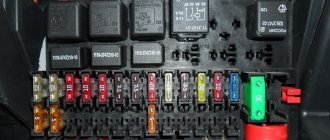
As noted earlier, the ECM contains numerous sensors, switches, relays, electric motors, electrical harnesses and fuses that protect one or another circuit from a short circuit to ground or the on-board voltage bus. All these elements can cause a malfunction.
Article [3] addresses in more detail the issues of diagnosing many of the main sensors and actuators of the ECM; below we will analyze in more detail the diagnosis of possible malfunctions of the electronic module of the throttle pipe and provide recommendations for their elimination.
For diagnostics and repairs, you must have a multimeter and a specialized diagnostic tool for reading ECM error codes. It is also possible to use a PC-based diagnostic device with a specialized program installed that reads and decrypts error codes.
At the beginning of troubleshooting work, it is necessary to check the presence of supply voltage, the quality of the connection of the battery terminals, and the integrity of the fuses.
It should be noted that when carrying out work on the vehicle’s electrical system, it is necessary to disconnect the terminals from the battery; also, all work is carried out at an ambient and engine temperature of at least +10°C, otherwise the engine will operate in emergency mode.
Difficulty starting the engine (error code P1640, P0601, P0606, P2105)
Often the cause of the malfunction is the ECU. This malfunction is typical for cars manufactured at the beginning of 2011.
When replacing the ECU or its hard reset with initialization using diagnostic equipment, as well as when replacing the ECU, the throttle position must first be set to zero.
To do this, when you turn on the ignition switch for the first time, keep the key in the “ignition on” position for at least 40 seconds, after which the engine is started.
Also, when replacing an ECU, you must strictly comply with the type and firmware of the software indicated on the nameplate of the controller being replaced.
The accelerator pedal is missing or malfunctioning (error code P2138, P2122, P2123, P2127, P2128)
When checking the serviceability of the accelerator pedal, it is necessary to disconnect the harness from it and, with the ignition on, check for the presence of +5 V voltage between pins 2-4 and 5-6 of the harness connector. If there is no power, check the corresponding power circuits.
Finally, the resistance of the accelerator sensors is measured in different modes of pressing the pedal; it should be within 600...2500 Ohms.
The engine does not develop the required power or stalls, the warning light is constantly on (error code P2135, P0122, P0222, P0223)
The operation of the throttle position sensor should be checked by temporarily replacing it with a known good one, as well as the corresponding connections.
The engine does not idle normally, the engine response to pressing or releasing the accelerator pedal is slow
Error code P1578, P2176, P1545 - check the adaptation of the minimum throttle position using diagnostic equipment.
Error code P1559 - check the position of the throttle valve with the electric drive de-energized using diagnostic equipment and visual inspection.
Error code P1558 - check the operation of the return spring by the time the damper returns to the limp home position.
Error code P2103, P2102, P2100 - these throttle actuator fault codes can occur due to a short circuit of the throttle module circuits to ground or on-board power supply, as well as when the throttle actuator power supply circuit is broken. Check the appropriate connections and electrical harnesses.
Throttle Actuator Control Monitoring
This check is carried out using a diagnostic tool.
Error Code P1335 (Check Throttle Position) - Throttle position is out of range.
Error code P1336 (checking the position mismatch of the throttle position sensors) - measure the voltage on the throttle position sensors (+3.3 V).
Error codes related to on-board voltage:
P-0560 - the voltage value in the circuits of terminals “30” and “15” differs from the norm;
P-0562 - voltage value is less than the lower threshold level;
P-0563 - voltage value above the upper threshold level;
R-1602 - loss of supply voltage.
If errors occur in the operation of the ECM system power supply, it is necessary to check the corresponding connections, the integrity of the harnesses, fuses, as well as the operation of the battery and generator.
Literature
1. D. Sosnin, M. Mitin. "Electronic accelerator drive of a modern car." Repair and Service, 2008, No. 12;
2. N. Pchelintsev “Operation of the electronic throttle pipe module for Euro-3 and Euro-4 engine control systems,” Repair and Service, 2009, No. 8;
3. N. Pchelintsev “Diagnostics of ECM of LADA KALINA cars”, Repair and Service, 2011, No. 1.
Author: Nikolay Pchelintsev (Tambov)
Source: Repair and service
Throttle position sensor
This sensor is a potentiometer. When you press the gas pedal, the position of the damper and the voltage supplied to the controller changes. When closed, the voltage is 0.7V, when fully open it is 4V. In accordance with these data, the sensor controls the fuel supply.
If a malfunction of the position sensor occurs, the controller will not be able to correctly determine the position of the damper. This results in the following malfunctions:
- in all engine operating modes, the speed begins to fluctuate; at idle, the speed will be increased;
- when you switch off the gear (neutral) while driving, the engine may stall;
- Sometimes the CHECK light may come on.
To check the functionality of the position sensor, you can use a multimeter. With the ignition on, the probes are connected to connectors B and C. Changing the position of the damper should lead to a change in voltage.
» alt=»»>
Why is it necessary to modernize the throttle valve on VAZ-2109, 2110, 2115
Spare parts stores sell throttle assemblies with valves of increased diameter (52, 54 and 56 mm) for VAZ-2109, 2110 or 2115 cars. According to the sellers, by installing such a valve instead of the standard 46 mm one, the car owner will receive significant advantages: the car becomes more responsive to the gas pedal, problems with idle speed disappear, the car's dynamics improve, and this is especially noticeable if you replace the standard air filter with a zero-resistance filter. The main argument that they try to convince car owners is that the engine requires more air to operate efficiently, for which it is necessary to replace the standard throttle assembly with an improved one. They even give figures: the diameter of the VAZ-2109 or VAZ-2110 receiver is 53 mm, and a damper with a diameter of 46 mm allegedly “strangles” the engine.
Examples of current prices
Considering that the throttle valve regulates the quality of engine operation, most car owners resort to completely replacing the unit with a new one. This is facilitated by both constant availability on the market and low price. Popular positions include:
- DAAZ 56mm (empty configuration, standard case) – RUB 1,243 .
- Tolyatti sport 2114-1148010-12 (52 mm, reinforced cable return spring) – RUB 1,684 .
- Tolyatti sport 2114-1148010-16 for 56 mm – 1,890 rubles .
- LLC VIE, VAZ 2110-2172 for 56mm (ready-to-install kit) – RUB 1,940 .
- DELPHI, VAZ 21116-1148010 – 6,316 rubles .
- PRO-SPORT 03534-St – 11,500 rub .
Throttle valve malfunctions VAZ 2114
The mechanism itself is not a complex structure and is designed for the entire service life of the engine. However, some design features of the motor and a number of external negative factors, over time, create obstacles to its normal operation. In most cases, problems with the damper are the result of simple contamination. The reasons for the appearance may be the following:
- untimely replacement of the air filter, resulting in the entry of dusty, unpurified air;
- the presence of defects and cracks in the air system and its elements (for example, a defective air filter, a torn pipe), the result is the same - contamination of the air flow;
- the appearance of carbon deposits and oil residues on the inner walls of the throttle assembly and valve.
The result of the above reasons is the incorrect operation of the unit; the damper may not fully open or close, which directly negatively affects the operation of the engine. Although the filtration and air flow purification process can be controlled, it will not be possible to completely get rid of carbon deposits. Therefore, automakers recommend periodic cleaning of the unit from contamination every 25 thousand kilometers. We believe that this recommendation is completely justified in the conditions of Russian reality, the quality of fuel and the condition of the road surface.
Troubleshooting
Before taking any action, you need to check the VAZ 2114 throttle valve for possible problems.
In order to accurately diagnose a malfunction or incorrect operation of the throttle, there are characteristic signs inherent to it. These are:
- Instability of engine speed at idle, their unreasonable increase;
- Periodically stalling engine;
- Jerking while moving;
- The discrepancy between the effort when squeezing the gas pedal and the final result (the proper reaction from the engine does not occur, power does not increase, the car does not pick up speed or does it late).
- Noticeable increase in fuel consumption in standard driving mode.
Please note that the causes of problems can be caused by: - A malfunction of the TPS sensor, as a result of which fuel is supplied to the system in the wrong amount. — Malfunction of the idle speed controller. Therefore, sometimes it is advisable to check these important elements of the system.
Cleaning the throttle valve of a VAZ 2114
There are two cleaning methods: - Without removing the unit; — And accordingly with its dismantling.
Which method should I choose? It all depends on the degree of pollution. If the mileage has been up to 25 thousand since cleaning or replacing the throttle. Then, most likely, it is possible to limit ourselves to superficial cleaning and prevention without removing the part. In other cases, it is recommended to completely dismantle the unit for deep, thorough processing, cleaning and gaining access to hard-to-reach places.
We will describe in detail the process of complete removal after which the first option will not be difficult to complete. So, let's begin:
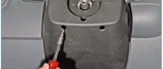
- To begin, unscrew the cap of the expansion tank with antifreeze. This is necessary in order to “relieve” the pressure and avoid antifreeze leaking out of the hoses.
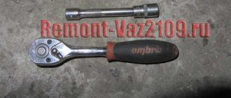
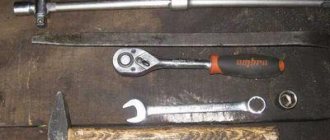
- Next, we need to unscrew and loosen all the clamps that tighten the hoses attached to the throttle block. The same applies to the air pipe. To carry out the work we will need a 13mm wrench or socket.
- After removing the clamps, disconnect the hoses themselves. We disconnect the pipe from only one side and, for convenience, move it to the side.
- Now remove the throttle cable from the throttle drive selector.
- Turn off the power to the sensors.
- Take the 13mm head, unscrew the two bolts and remove the throttle assembly. Remove the old gasket.
- To treat contamination, you can use carburetor cleaner and a clean rag or rag. If the degree of contamination is very high, then you can use a toothbrush with hard bristles.
- Just before cleaning, disconnect the idle air control. Apply the product to the contaminated surface. Using progressive movements, remove carbon deposits from the metal surface. If you are not satisfied with the result, repeat the operation again until complete cleansing. It is very important to clean or blow out the channels that are in the product. A large amount of dirt accumulates there. It is most convenient to carry out purging using compressed air. To do this, you can use a regular car pump.
- If the sensor socket and the sensor are clogged, be sure to clean them too.
- Do not forget to carefully clean the junction of the throttle assembly and its internal cavity. To do this, apply some cleaning product to a rag. Distribute evenly on the inner walls of the parts. Take a brush and clean the problem areas. After finishing the treatment, wipe the cleaned areas with a damp cloth and remove any remaining dirt.
- After washing the unit, it is recommended to clean and blow out the disconnected pipes.
- We expect a short amount of time.
- We install a new gasket at the junction of the throttle assembly.
- We attach and secure the knot in place.
- We connect the IAC sensor.
- We pull the hoses onto the fittings of the cooling system and connections to the adsorber.
- We put on the throttle body pipe.
- We fix the cable on the drive.
- Tighten the clamps of all attached elements.
- We connect the sensor chips.
- Close the cap of the expansion tank with coolant.
- We start the car and test its operation.
The non-removal method is somewhat similar to the one we described earlier. The only difference is that we will only remove the air duct pipe and nothing else. The work steps are as follows: — Remove the pipe; — We repeat point number 10 of the previous method. — We connect and secure everything in the reverse order, not forgetting to replace the old gasket with a new one.
Keep in mind that this method is most suitable for preventative, light, superficial cleaning. If malfunctions or incorrect operation of the engine occur, use only the removal method. Now we know how to clean the throttle valve on a VAZ 2114 using two different methods, quickly and without much difficulty.
Instructions for dismantling the mechanism
Replacing the throttle valve on a VAZ-2114 does not require any special professional skills, so even a novice driver can carry out all the work. To carry out the work, you need to arm yourself with all the necessary equipment: a 13mm socket wrench, screwdrivers, cleaning agent.
The procedure for removing the remote control is as follows:
- The plastic cover is removed from the top of the motor, and the hoses that provide ventilation are detached.
- It is also advisable to make sure that lubricant residues are in the air pipe; this will indicate that the mechanism really needs urgent cleaning.
- Then you need to remove the cap that covers the expansion tank to reduce pressure in the system, remove the clamps with fasteners and disconnect all supply hoses.
The final step in the throttle body removal process is to remove the hose that vents the fuel tank, disconnect the cable, and release the two bolts. When the mechanism is dismantled, based on a visual inspection, a conclusion can be made about its level of contamination. Then proceed to complete or partial cleaning of the throttle valve.