Design and operating principle
When an electric current passes through the coil, an electromagnetic field is created, under the influence of which the armature moves inside the core. When the power is cut off, the field disappears and the armature begins to move freely along the core.
The ignition relay includes the following components:
- Electromagnet;
- Anchor;
- Return spring;
- Contacts;
- A pair of windings.
The electromagnet, in turn, includes two coils in its design.
Coil type
Peculiarities
It is connected to the ignition relay housing, as well as the control output
The retractor coil is connected to the motor contact as well as the control terminal
Device location
The operating principle of the node is based on the following:
- When voltage is applied to the control contact, electric current begins to flow through the coils. This leads to the appearance of an electromagnetic field, under the influence of which the armature moves, compressing the return spring;
- The armature also moves the bendix, then the rod, which closes the contacts connecting the battery with the starter motor;
- When the contacts are closed, a plus is supplied at the output of the retractor coil, which moves to the motor output. So the current stops passing through it - the magnetic field disappears, but the armature remains in the retracted position due to the influence of the magnetic field from the holding coil;
- The armature returns to its original position after the engine is started and the power is turned off, which occurs under the action of the return spring;
- In this case, the contacts open, the bendix is disengaged;
- The contacts of the retractor relay are bolts that are installed in the textolite cover, as well as plates (can be round or rectangular). They close the bolts when the armature moves.
Coil type
Peculiarities
Device location
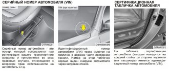
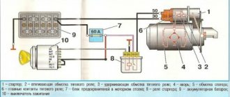
Ignition switch consumers. This article will be useful to those who want to upgrade the ignition switch (for example, start the engine with a button) or are experiencing problems with the lock. Only the electrical part of the lock is described. We will consider the ignition switch in the VAZ-2114 version. It, unlike the VAZ-2108 lock, works in conjunction with the ignition relay.
0 - all consumers are turned off (used extremely rarely) 1 - ignition on 2 - starter on 3 - parking (key removed from the lock) Voltage from the battery is always supplied to contacts 7 (pink) and 8 (brown) of the lock. These wires are connected in parallel and connected in the mounting block. The division into two wires was apparently done for reliability, or it may have developed historically - these wires can be replaced with one wire.
Load of wires and contacts of the lock
The brown and blue-black wires power the ignition relay, power window relay coils and heated seat relays, carburetor electronics, on-board computer and instrument panel, lamp monitoring relays, reverse lamps, front wiper, and also provide a signal to the ECU, immobilizer and on-board computer .
The black wire (pin 2) powers the “dimensions”, the engine compartment lamp, the relay coils for the fog lights and high beams, the license plate illumination, the on-board computer, the button and instrument panel illumination.
The blue wire (pin 4) is the most loaded. It powers the heater fan, rear fog lights, rear window and headlight wipers, relay coils for headlight wipers and heated rear window, low and high beams, and glove compartment lighting. This wire is disconnected when the starter is turned on (position 2 of the lock).
Pink connects the black, blue and red wires, therefore the load on it is summed up.
The armature is also moved by the bendix, and later by the rod, which closes the contacts that the battery closes with the starter motor. When the contacts close to the terminal of the retracting winding, which goes to the motor terminal, a plus is applied and the current stops passing through it - the magnetic field disappears, but the armature still remains in the retracted state under the influence of the magnetic field of the holding winding.
The armature returns to its original position after starting the engine and turning off the power by the action of the return spring, opening the contacts and disengaging the bendix. The contacts of the pull-in relay are bolts that are fixed in a textolite cover and rectangular or round plates that close the bolts when the armature moves.
Coil type
Peculiarities
Fuses and relays VAZ 2108, 2109, 21099
Welcome! Starter activation relay - many will think at this point that we are talking about a retractor relay, in fact this is not so, in total the starter has two relays, one that turns it on and the second one that extends the bendix and pushes its gear onto the crankshaft pulley (the second is the same solenoid relay), if the first one fails (Happens occasionally mainly due to overloads on it or due to faulty wiring), you will not be able to start the starter and therefore the car will not start, if If the second one fails, the situation will be slightly different, but specifically the car may also not start and the clicking will occur when the key is turned, but this can still be said acceptable, but if this relay fails completely and does not return the bendix to its reverse position, then the following will happen, when you turn the key, the starter will begin to turn the engine of the car and eventually it will start, but when you return the key after the engine has started in the reverse position, the bendix at the starter will not turn back (the solenoid relay does not work) and In a very short time the starter will become unusable.
Note! To change the relay that is responsible only for turning on the starter, you need to stock up on: Only one “8” wrench, more for you and you don’t need to take anything, but maybe one more wrench so that, just in case, the minus terminal with Reset the battery!
1. If you carefully read the above text, you will immediately guess how to remove this relay, but we will still instruct you, find this relay in your car (the location is shown in the photo above), you see a block of wires connected to it, then disconnect it, and after it is removed and set aside, take a wrench in your hands and unscrew the relay mounting nut with it and then remove it, by the way, if the work is done in the rain or in very wet weather, or if you are simply afraid of a short circuit in the wiring (B In this case, the entire wiring will burn out and will need to be replaced), then protect yourself by disconnecting the wire from the minus terminal on the battery to do this; if you don’t understand how to do this, then study “this article”, it says everything in the first paragraph.
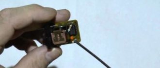
Note! To check whether the relay is working or not (We don’t recommend just taking a new relay, always inspect everything), you can use 2 different methods, the first is that you have to remove the cover from the mounting block and take it out from there a relay with exactly the same markings as yours, the relay goes to turn on the starter, after removing these two relays, change these two relays and try to start the car, if it doesn’t start, it means the problem is not in the relay and you need to find the problem either in the starter itself or in the ignition switch, The second method assumes that you will find a jumper wire (Indicated by a blue arrow, the wire can also be used) and bring its conclusions to the wire block, specifically to its contacts “30” and “87” (These are the lower and upper contacts of the block, take a closer look to the relay they are marked on it, or for clarity, look at the photo they are indicated by a reddish arrow, although there is a block from a completely different car, but it is actually the same and on it you can understand where these two contacts are located) if the car starts immediately (Don’t forget the jumper when it will start to start immediately, remove it) then it’s all in the relay, if not, then look further (When you do the 2nd method, do not forget to turn the key in the ignition until all the devices light up)!
Most electrical circuits are protected by fuses. Electric motors of gear motors (windshield wipers, rear window wipers (VAZ-2108, -2109), headlights - if installed) are protected by automatic reusable bimetallic fuses. The power supply circuit of the injection system (engine 2111) is protected by a fuse-link made of wire with a conductor of reduced cross-section (1 mm2).
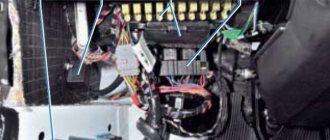
The relay and fuse box in the VAZ 2108-09-099 (carburetor, injector) is located under the hood, in the compartment in front of the windshield on the left side.
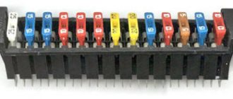
Fuse mounting block 2114-3722010-18
| Relay/fuse no. | Decoding |
| K1 | Headlight wiper relay |
| K2 | Relay-breaker for direction indicators and hazard warning lights |
| K3 | Windshield wiper relay |
| K4 | Lamp health monitoring relay |
| K5 | Power window relay |
| K6 | Horn relay |
| K7 | Relay for turning on electric rear window heating |
| K8 | High beam relay |
| K9 | Low beam relay |
| F1-F16 | Fuses |
Fuse mounting block 2114-3722010-60
| Relay/fuse no. | Decoding |
| K1 | Headlight wiper relay |
| K2 | Relay-breaker for direction indicators and hazard warning lights |
| K3 | Windshield wiper relay |
| K4 | Relay for monitoring the health of brake lamps and side lights |
| K5 | Power window relay |
| K6 | Horn relay |
| K7 | Relay for turning on electric rear window heating |
| K8 | High beam relay |
| K9 | Low beam relay |
| F1-F16 | Fuses |
| F1-F20 | Spare fuses |
Fuse mounting block 17.3722
| Relay/fuse no. | Decoding |
| 1 (K6) | Headlight wiper relay |
| 2 (K1) | Rear window washer timing relay |
| 3 (K2) | Relay-breaker for direction indicators and hazard warning lights |
| 4 (K3) | Wiper relay |
| 5 | Contact jumpers in place of the lamp health monitoring relay |
| 6 (K10) | Heated rear window relay |
| 7 | Spare fuse |
| 8 (K5) | High beam relay |
| 9 (K11) | Low beam relay |
| 10 | Fuse |
| 11 (K9) | Engine cooling fan motor relay |
| 12 (K8) | Horn relay |
Decoding the fuses of the mounting block for VAZ 2109, 2108, 21099
F1-F16 - mounting block 2114-3722010-60, 2114-3722010-18.
Numbers from 1 to 16 - old-style mounting block 17.3722
| Fuse N | Decoding |
| 1 (8 A), F9 (7.5 A) | Right fog lamp |
| 2 (8 A), F8 (7.5 A) | Left fog lamp |
| 3 (8 A), F1 (10 A) | Headlight cleaners (at the moment of switching on). Relay for turning on headlight cleaners (contacts). Headlight washer activation valve |
| 4 (16 A), F7 (30 A) | Headlight cleaners (in operating mode). Relay for turning on headlight cleaners (winding). Heater fan motor - heater fuse Window washer motor. Rear window wiper motor. Rear window washer timing relay. Valves for turning on the windshield and rear windows. Relay (winding) for turning on the electric fan of the engine cooling system. Relay (coil) for turning on the heated rear window. Rear window heating indicator lamp. Glove compartment lamp |
| 5 (8 A), F16 (15 A) | Direction indicators and relay-interrupter for direction indicators and hazard warning lights (in turn indication mode). Turn signal indicator lamp. Rear lights (reversing lamps). Gearmotor and windshield wiper activation relay. Generator excitation winding (when starting the engine). Brake fluid level warning lamp. Oil pressure warning lamp. Carburetor air damper warning lamp. Parking brake warning lamp. "STOP" light display lamp. Coolant temperature gauge. Fuel level indicator with reserve warning lamp. Voltmeter |
| 6 (8 A), F3 (10 A) | Rear lights (brake lamps). Interior lighting |
| 6 (8 A), F6 (30 A) | Power windows for front doors. Power window relay |
| 7 (8 A), F10 (7.5 A) | License plate lights. Engine compartment lamp. Instrument lighting lamps. Indicator lamp for external lighting. Heater lever illumination display. Cigarette lighter lamp |
| 8 (16 A), F5 (20 A) | The electric motor of the engine cooling system fan, and its activation relay (contacts). Sound signal and relay for its activation |
| 9 (8 A), F10 (7.5 A) | Left headlight (side light). Left rear light (side light) |
| 10 (8 A), F11 (7.5 A) | Right headlight (side marker). Right rear light (side light) |
| 11 (8 A), F2 (10 A) | Direction indicators and hazard warning relay-breaker (in hazard warning mode). Hazard warning lamp |
| 12 (16 A), F4 (20 A) | Rear window heating element. Relay (contacts) for turning on the heated rear window. Plug socket for portable lamp. Cigarette lighter |
| 13 (8 A), F15 (7.5 A) | Right headlight (high beam) |
| 14 (8 A), F14 (7.5) | Left headlight (high beam). Indicator lamp for high beam headlights |
| 15 (8 A), F13 (7.5 A) | Left headlight (low beam) |
| 16 (8 A), F12 (7.5 A) | Right headlight (low beam) |
Diagram of the mounting fuse block for VAZ 2109, 2108, 21099 (block 17.3722)
(the outer number in the designation of the wire tip is the number of the block, and the inner number is the conventional number of the plug)
| Relay/fuse no. | Decoding |
| K1 | Rear window washer timing relay |
| K2 | Relay-breaker for direction indicators and hazard warning lights |
| K3 | Wiper relay |
| K4 | Lamp health monitoring relay (contact jumpers are shown inside, which are installed instead of the relay) |
| K5 | High beam relay |
| K6 | Relay for turning on headlight cleaners |
| K7 | Power window relay |
| K8 | Horn relay |
| K9 | Engine cooling fan motor relay |
| K10 | Heated rear window relay |
| K11 | Low beam relay |
Diagram of the mounting fuse block for VAZ 2109, 2108, 21099 (2114-3722010-60)
| Relay/fuse no. | Decoding |
| K1 | Headlight wiper relay |
| K2 | Relay-breaker for direction indicators and hazard warning lights |
| K3 | Windshield wiper relay |
| K4 | Lamp health monitoring relay |
| K5 | Power window relay |
| K6 | Horn relay |
| K7 | Heated rear window relay |
| K8 | High beam relay |
| K9 | Low beam relay |
| F1-F20 | Fuses |
- Ignition switch wires 2108, 2109, 21099
- Pinout of the ignition switch VAZ-2109
- Ignition switch diagram for VAZ 2109 (carburetor, injector): photo Ignition switch diagram
- Types of the castle
- headlight cleaner relay (K6);
- rear window washer relay (K1);
- turn signal and hazard warning relay (K2);
- windshield wiper relay (K3);
- contact jumpers;
- rear window heating relay (K10);
- spare fuse;
- headlight high beam relay (K5);
- low beam headlight relay (K11);
- fuse;
- radiator cooling fan relay (K9);
- horn relay (K8);
- K1 – rear window washer relay;
- K2 – turn signal and hazard warning relay;
- K3 – windshield wiper relay;
- K4 – lamp serviceability relay;
- K5 – high beam headlight relay;
- K6 – headlight cleaner relay;
- K7 – power window relay;
- K8 – sound signal relay;
- K9 – Cooling system fan relay;
- K10 – rear window heating relay;
- K11 – Low beam headlight relay.
- K1 – headlight cleaner relay;
- K2 – turn signal and hazard warning relay;
- K3 – windshield wiper relay;
- K4 – lamp serviceability relay;
- K5 – power window relay;
- K6 – sound signal relay;
- K7 – rear window heating relay;
- K8 – high beam headlight relay;
- K9 – low beam relay;
- F1-F20 – fuses.
VAZ 2109 starter relay diagram
Do you hear clicks or are there no traces of them? The driver releases the key and joy: the fan picks up speed. We take the sword and install it in the chuck of a hand drill: let's try to make a thread in the sleeve.
The owner turns the key to the third position, but again there is silence: the starter does not turn at all. The starter relay is located under the hood on the front panel. The VAZ-2108 and VAZ-2109 cars use a single-wire electrical system with a rated operating voltage of 12 V. This is truly a masterpiece of futurism! Plug connector for connecting to the lamp for individual interior lighting; I. It is pressed into the cover 14. Dear visitor, you have entered the site as an unregistered user. A small problem is enough for the starter shaft to become slightly misaligned: the narrow gap disappears completely. Answer 1: Change the bridge and charging relay, which comes with the brushes. These consumers are connected directly to the generator-battery line.
Starting currents are not protected by specific fuses. Yes, here it is: right on the frame, looking at you with four contacts to the left of the vacuum seal. Relay for turning on headlight cleaners contacts. Remember the starter connection diagram; a similar plan will be useful to you more than once when you do your own car repairs. It's time to change the solenoid relay.
He turns the ignition key, and the STOP lights and oil pressure gauge come on, but the battery light doesn’t want to light up. Question: what about the battery charge indicator lamp? Headlight high beam relay; KB. Site information is collected online or sent by visitors. Relay for low beam headlights. Proceed to unscrew the lower bolt of the device and remove the remaining fasteners from the starter.
For those who are not yet in the subject, here is a photo. A marksman is like a girl: the object is fragile. Such consumers include: emergency alarm, sound signal, brake light lamps in the rear lights, 16-pin socket for a portable lamp, interior lamp. Carry out the following actions at low speeds. Volts with wires and using this diagram, you can independently find and fix minor problems in electrical equipment.
Approximately at the level of the mounting block connector, somewhere under the hood. Relay-breaker for direction indicators and hazard warning lights; KZ. The supply voltage is supplied to most consumers through the ignition switch. How can you get it out yourself? The rotation of the rear end of the armature shaft occurs in a cermet bushing. This operation can be performed several times. In the instrument panel wiring harness, the second ends of the white wires are brought together to one point, which is connected to the instrument lighting switch. Before examining specific cases, watch a video about repairing starters in a specialized service center. While you are enjoying the smell of iron, your significant other will buy a magazine where they will read an article about the history of the VAZ 2109 brand and regret that they purchased a non-domestic unit at a lower price. And we encountered the following difficulty: the starter does not turn when you turn the key, but at the same time you hear clicks, which means the retractor relay is working.
Rear window cleaner motor. Get ready for a shopping trip. The installation dimensions of the above starters are almost the same - the only differences are in the design of the drive and the collector assembly.
Diagram of the contactless ignition system for VAZ 2108, VAZ 2109, VAZ 21099 Fig. Excessive force or slight misalignment can break it. Where is the starter relay for the BAZ 2110? The front end is placed in a bushing that is pressed into the clutch housing.
Decoding the fuses of the mounting block for VAZ 2109, 2108, 21099.
- 1 (8 A) F9 (7.5 A) – Right fog lamp;
- 2 (8 A) F8 (7.5 A) – Left fog lamp;
- 3 (8 A) F1 (10 A) – Headlight washers, relay and washer valve;
- 4 (16 A) F7 (30 A) – Headlight cleaners, headlight cleaner relay, heater fuse, front and rear window washer motor, radiator cooling fan relay, glove compartment light, rear window heating relay;
- 5 (8 A) F16 (15 A) – Oil pressure lamp, turn and hazard indicators, rear lights, windshield wiper switch gear, brake fluid level lamp, parking brake lamp, “STOP” lamp, temperature and fuel level indicator.
- 6 (8 A) F3 (10 A) – Tail lights and interior lighting.
- 6 (8 A) F6 (30 A) – Window regulators and power window relays.
- 7 (8 A) F10 (7.5 A) – Rear state lighting. numbers, dashboard lighting, cigarette lighter lighting, heater lever lighting.
- 8 (16 A) F5 (20 A) – Horn, engine cooling fan motor and its relay.
- 9 (8 A) F10 (7.5 A) – Dimensions of the left headlight and left rear light.
- 10 (8 A) F11 (7.5 A) – Dimensions of the right headlight and right rear light./li{amp}gt;
- 11 (8 A) F2 (10 A) – Hazard alarm and its lamp.
- 12 (16 A) F4 (20 A) – Cigarette lighter, heated rear window and its activation relay.
- 13 (8 A) F15 (7.5 A) – High beam of the right headlight.
- 14 (8 A) F14 (7.5) – High beam of the left headlight and lamp for turning them on.
- 15 (8 A) F13 (7.5 A) – Low beam of the left headlight.
- 16 (8 A) F12 (7.5 A) – Low beam of the right headlight.
- Ш1-Ш4 – connects to the dashboard harness;
- Ш9 – connects to the rear harness.
Connection numbers in the engine compartment:
- Ш5, Ш6 – the front harness is connected;
- Ш7, Ш8 – the wiring harness of the left mudguard is connected;
- Ш11 – the wiring harness of the air supply box is connected.
If the car shows signs of malfunction, there are signs of breakdown of elements of the ignition system, do not rush to immediately blame the starter or module for everything. Often the culprit may be an element that is insignificant in size and cost - the relay.
Dismantling works
To check the relay you need:
- Arm yourself with an ohmmeter or a multimeter more suitable for a motorist, which has all the necessary modes;
- Check resistance indicators;
- We check the holding coil by connecting one terminal of the tester to the relay connection terminal, and the second to ground, that is, the housing;
- Next, the pull-in winding is checked. Here the terminals are connected to the starter motor field winding connection bolt and the control wire connection bolt;
- If there is no resistance, there is only one output - failure.
Checking with a multimeter
There is no point in repairing the ignition switch. The element can only be replaced. Plus, it costs pennies.
To replace, you will need to perform a few simple steps. You don't have to be a car repairman here.
- Disconnect the battery by removing the negative terminal.
- Using a slotted screwdriver, unscrew the four screws on the steering column housing. This will allow you to easily remove the element.
- Using a Phillips screwdriver, unscrew another screw that holds the bottom of the casing in place.
- Remove the steering column protective cover.
- At the bottom there is a block of the harness with wires where the ignition relay is connected.
- To replace the relay, you simply need to disconnect the device from the block and install a new element in its place.
- Check the performance of the car with a new transmission.
As you can see, there is nothing difficult about checking and replacing the device. It does not fail very often, but it is worth monitoring the condition of the ignition relay.
Dismantling works
Checking with a multimeter
Dismantling works
Ш9 - block connecting to the rear wiring harness;
Ш1-Ш4 - blocks connecting to the instrument panel wiring harness.
Ш5 and Ш6 — blocks for connecting the front wiring harness;
Ш7 and Ш8 — blocks for connecting the wiring harness of the left mudguard;
Ш11 - block for connecting the wiring harness of the air supply box.
In more recent VAZ models, the stove is powered directly through the ignition switch.
The power supply circuit of the injection system (engine 2111) is protected by a fuse-link made of wire with a conductor of reduced cross-section (1 mm2). The battery charging, ignition (carburetor engines), engine starting, and the “generator - ignition switch - mounting block” circuits are not protected.
Powerful consumers (starter, headlights, cooling system fan motor, electric fuel pump, etc.) are connected via a relay.
Fuse mounting block 2114-3722010-60
Fuse mounting block 17.3722
Decoding the fuses of the mounting block for VAZ 2109, 2108, 21099
F1-F16 - mounting block 2114-3722010-60, 2114-3722010-18.
If some devices on your VAZ 2110 or VAZ 2112 car have stopped working, fuses or relays may be to blame. At the very least, the first thing you need to do is check them, and then draw some conclusions regarding the malfunctions.
Correct diagnosis of many electrical problems will allow you to accurately determine the cause of the inoperability of a particular unit. To find out what the fuses and relays of the VAZ 2110 - 2112 are responsible for and how to find the right one, read this article.
As in many other cars, in the VAZ-2112 and VAZ-2110, when the engine is turned off, the devices are powered directly from the battery. When the engine is running, voltage is supplied to the devices from the generator, which simultaneously charges the battery. If the current exceeds the permissible value or a short circuit occurs, the circuit fuse will blow. Powerful electrical appliances are connected via relays.
The fuse and relay box is located on the left, lower part of the instrument panel. It is accessible by pressing the button and folding the lid down. To remove fuses, there are special non-conductive pliers in the upper left part of the mounting block.
1 - K5 - high beam relay. If the high beam in two headlights does not work, check this relay. If one of the high beam headlights does not work, check fuses F3 and F13, as well as the lamps and the high beam switch.
2 - K4 - low beam relay. If the low beam in both headlights does not work, check this relay. If only one low beam headlight does not work, check fuses F2 and F12, as well as the lamps themselves and the light switch.
3 - K1 - lamp health control relay.
4 - non-conductive tweezers for removing fuses.
5 - power window relay. If your power windows stop working, check this relay. It could also be in fuse F5, or in the window lift drive system itself. To get to the mechanism, you need to remove the door trim. Check the electric motor, the appearance of the gears and the absence of binding of the mechanism.
6 - K3 - turn signal and hazard warning relay. If your turn signals or hazard lights do not work, check this relay and fuse F16, as well as the turn signal lamps themselves and their switch.
7 - starter relay. If the car does not start and the starter does not turn, check this relay. It could also be a dead battery, as well as the starter mechanism itself.
8 - backup fuses.
9 - fog light relay. If the fog lights do not work, check this relay and fuses F4 and F14. Also check their connection diagram, the serviceability of the wiring and connectors, as well as the lamps in the headlights and the power button.
10 - K2 - windshield wiper and washer relay. If your windshield wipers or windshield washer do not work, check this relay. Also check the wiper motor, washer pump and washer fluid level in the washer reservoir.
11 - K7 - rear window heating relay. If the heating does not work and the rear window fogs up, check this relay and fuses F8 and F9. Also check the connection contacts to the terminal points of the heating elements (at the edges of the glass at the rear pillars). If everything is in order, but the heating does not work, the issue may be in the wiring (the wires are frayed or something else).
12 - K6 - add. relay, ignition relay. If your ignition does not turn on or is having problems with it, check this relay. This relay protects the ignition switch contacts from burning. Also check the ignition switch itself and the contact group.
13 - row of fuses F1-F10
14 - row of fuses F11-F20
Circuit breakers
Now let's see which fuses are responsible for what in the same mounting block. I will also give the main reasons for troubleshooting.
F1 (5 A) - license plate lighting lamps, instrument panel lighting, side indicator lamp on the panel, trunk lamp, left side lights. If any of the listed lamps do not work, check this fuse, as well as the lamps themselves and their contacts. If everything is in order, check the headlights switch.
F2 (7.5 A) - low beam in the left headlight. If both low beam headlights do not work, also check relay K4 and the lamps themselves. It could also be the light switch and its contacts.
F3 (10 A) - high beam in the left headlight. If both high beam headlights do not work, check relay K5, the lamps themselves and the high beam switch.
F4 (10 A) - front fog light on the right side. If both fog lights do not work, check relay 9 and the headlight bulbs themselves, as well as the switch and its contacts.
F5 (30 A) - window motors. If the power windows do not work, check this fuse and relay 5. In winter, check if the windows are frozen, warm them up and clear them of ice if necessary. It could also be the window lift motor, its mechanism and gears; in order to get to it, you need to remove the trim of the desired door.
Mounting block with fuses for VAZ 2109 (diagram)
Fuse blocks installed on old and updated versions of VAZ 2109 cars serve to combine all electrical wiring.
The main task of the power supply is to prevent breakdowns of electrical equipment installed in the car.
The entire line of VAZ 2109 cars can be divided into two branches - those produced before 1998 and those produced after 1998.
Older cars are equipped with fuse blocks whose marking is 17.3722. This power supply consists of a housing and an engineering board. Wire contacts, fuses and relays are soldered to the board.
Newer versions of nines, the production of which began in 1998, here the power supply is marked 2114-3722010-60. Here we are already seeing fuses.
The required mounting block is also located the same everywhere - in the engine compartment opposite the driver's seat, almost under the windshield.
Location
Are there any differences between the old and new versions of the power supply? Of course. They are as follows:
- The parts of the mounting block are marked differently;
- The fuse ratings are different;
- The new power supply does not have a relay for the cooling system fan motor and a time relay for the rear window washer device.
What does the VAZ 2109 ignition relay consist of?
When an electric current passes through the coil, an electromagnetic field is created there, and under its action the armature moves inside the core. When the power is turned off, the field disappears and the armature moves freely in the core. The VAZ 2109 ignition relay consists of an electromagnet, which is wound from an armature, a return spring, contacts and two windings.
The electromagnet consists of two coils: holding and retracting. The retractor is connected to the electric motor contact and the control terminal, and the retainer is connected to the relay body and the control terminal. When voltage is applied to the relay control contact, an electric current flows through the coils, creating an electromagnetic field there, and under its action the armature moves and compresses the return spring.
Where is the VAZ 2109 starter relay located - Car lover's blog
The fuse mounting block is a box with installed fuse links and protective parts. This is necessary to insure against voltage drops in the on-board network caused by short circuits or damage to devices. Our editors have collected information about locating the VAZ 2114 starter relay and other important inserts to make the search as easy as possible.
On the fourteenth model with an 8-valve engine, two power supplies are installed. The first is located inside the engine compartment. More specifically, the block is located under the windshield on the right side in the direction of travel of the car. Externally, the device looks like a black box with a plastic lid.
The indoor unit is located in the cabin, under the feet of the front passenger on the left. The side part of the instrument panel is made in the form of an inspection hatch that provides access to the protective elements.
Starter protection is designed to protect the circuit of the corresponding unit from overload or short circuit. In appearance, it is a standard four-pin device suspended on a bolt inside the engine compartment.
In this case, the injector or carburetor is designed in the same way - the block is suspended independently. The exact location of the element is impossible to describe. Thanks to the “special” approach of the designers, the hitch may differ depending on the year of manufacture. Therefore, it is best to start your search from the starter terminals and move along the wires to the device itself.
The starter retractor is an electromechanical device installed directly inside the unit housing. The part is responsible for the clutch of the engine flywheel with the electric motor gear.
The search is carried out by visual inspection. The retractor is located in the same housing as the main unit and has two large contacts coming from the ignition switch and the battery.
The starter interlock device is a separate unit that prevents the rotation of the electric motor armature after starting the power unit of the machine. Thanks to a well-thought-out design, after turning the ignition key, a group of contacts is closed, passing current to the starter. After the motor spins up and the circuit opens, the diode closes and the excited windings are de-energized.
The exact location of the block differs depending on the year of manufacture. The type of power plant also affects the installation.
The main relay is designed to start the vehicle's power plant. This unit is powered through the ignition switch and supplies voltage to the injectors, spark plugs, ignition module and fuel pump. Thus, if the unit breaks down, all the necessary electrics are de-energized and the car will not start.
On the VAZ 2114 the block is located near the ECU under the dashboard on the passenger side. There is also a fuel pump protection element nearby.
The ignition relay, by definition, is another name for the GR. The insert is located inside the cabin on the right side of the dashboard. To access the insert, it is necessary to dismantle the protective plastic plate where the bolt is installed.
The intended purpose of the device is to close the circuit that triggers the start of the power plant.
This unit is responsible for charging the battery and the amount of charge supplied. The part is located on the back wall of the generator itself. To prevent getting wet, the element is covered with a plastic cover. Externally, the device is a black tablet with two graphite brushes.
Another name is voltage regulator. This was deliberately thought out, since the design performs two functions at once - protective and regulating.
The fuel pump fuse together with the corresponding element is located inside the cabin unit at the feet of the front passenger. The panel itself is equipped with three inserts, the first of which is the necessary element. The corresponding fuse is located nearby. In the corresponding photos you can see the exact position of the part against the general background.
The price of this unit starts from 100 rubles. A fuse can be bought for 10-15 rubles.
This element is necessary for thermal regulation of the machine engine. When driving at low speed, the motor overheats, which requires forced activation of the cooling fan. The detail is responsible for exactly this.
The insert is also located inside the passenger compartment at the feet of the front passenger. According to the factory instructions, the required part is installed first on the left. However, the exact location and order may vary depending on the year of manufacture.
The windshield wiper or wiper protection is located under the hood inside the main unit. The part is responsible for the operation of the breaker and the supply of power to the mechanism drive. According to the standard instructions, the insert is marked K3.
Heater relay
In fact, this is an independent element of the electrical network, responsible for the operation of the stove fan. On standard designs, the regulator can set three positions - minimum, medium and maximum airflow.
The exact location is determined by the tidy - exactly in the center of the panel, under the heater.
Turns relay
An element included in the instruments of the main unit near the left front pillar of the car. The insert is responsible for sending a signal to the turn signal switches and an emergency signal. In the event of a failure, the lamps may light continuously or not light up.
The rear fog light protector is designed to protect the circuit from overload or short circuit. Usually displayed inside the cabin near the light switch. The location of the insert on each car may differ, since the VAZ 2114 does not have lights in the factory configuration. This circumstance provokes buyers to install the equipment themselves or order installation when purchasing from an authorized dealer.
Author of the material: Borisov Maxim
VAZ 2109 starter repair
The most unpleasant surprise is when the car breaks down before it can start. Only the starter can be to blame for this. There is no need for diagnostics here and tricks won’t work here. A starter malfunction is visible to the naked eye and cannot be interpreted in two ways. Only dismantling and repair.
The VAZ 2109 is not a spaceship, but it’s hard to remove the starter with bare hands, and experience won’t hurt either. The car is quite reliable and easy to operate, but, as a rule, almost all nines have an impressive mileage.
Since the starter is the most loaded unit in the starting system, it fails quite often. If used incorrectly, even more so. Therefore, repairing the VAZ 2109 starter is not a tragedy, but rather a pattern.
- Starter device
- Removing the starter
- VAZ 2109 starter repair
- Solenoid relay
- Starter brushes
Starter device
Without removing the starter from the car, we are unlikely to be able to carry out a proper repair of the VAZ 2109 starter, so it must first be dismantled. But before that, let’s briefly touch on the design of the starter so that it is clear what we are talking about.
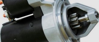
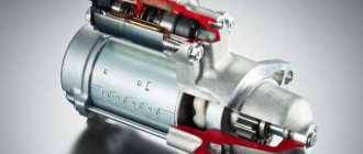
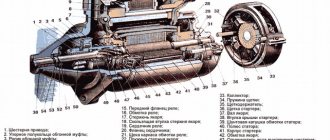
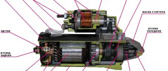
The starter is an ordinary powerful traction electric motor, consisting of the engine itself and a retractor relay - a device that is responsible for engaging the starter teeth with the teeth of the car engine flywheel. The figure shows its general structure, and we will get to know it in more detail after disassembling it:
- Manifold cover.
- Engine housing.
- Drive cover.
- Bendix.
- Electric motor shaft.
- Solenoid relay.
- Terminals.
- Armature winding output.
This is a general design of the starter, but it is already clear how the unit works - when you turn the ignition key, voltage is supplied to the starter terminals, the solenoid relay is activated, which engages the starter Bendix gear and the engine flywheel, the electric motor turns over the internal combustion engine, it starts, and after that gear retractor and bendix mechanism move the gear into place. That's it in a nutshell. Now let's start dismantling.
Removing the starter
We will be able to detect and eliminate the cause of the malfunction only when we remove and disassemble the starter. For removal we will need the usual tools and a set of sockets. We carry out the process in this order:
- Disconnect the negative terminal from the battery and disconnect the block with the wire from the connector on the solenoid relay housing.
- Using a 13 key, remove the wires from the starter terminals.
- Remove the crankcase protection and unscrew the starter housing from the cylinder block.
- With a slight movement, remove the starter and place it on the operating table.
VAZ 2109 starter repair
As a rule, the main malfunctions of the starter are breakdowns of the retractor relay, wear of the bushings and wear of the electric motor brushes. In rare cases, the winding may short out due to overheating, but then the characteristic smell will immediately alert you to such a problem.
First, let's arm ourselves with a regular tester and check the starter windings and the functionality of the solenoid relay. Everything is clear with the windings - if they do not ring, either rewind or change the starter. With a retractor relay it is more difficult.
Solenoid relay
We supply 12 volts to the positive terminal of the relay, while the negative terminal can simply be pressed against the body. If the relay works, everything is fine. If not, it’s most likely due to oxidized contacts or a worn mechanical part. Then the relay levers and racks must be lubricated and the contacts cleaned.
We check the resistance on the windings of the solenoid relay. On the pull-in winding, the ohmmeter should show 0.55 Ohm, on the holding winding - 0.73-0.79 Ohm. To rewind relay windings, you need special equipment and a special wire. This is done only in specialized workshops. We will also not rewind the windings, and in case of a break we will simply replace the solenoid relay.
Starter brushes
Very often, the cause of starter failure can be wear of the brushes. There is only one way to check this - remove the brushes and measure their wear. The length of the brush should not be less than 10-11 mm, if less, replace them with new ones.
If we have already removed the starter, then it makes sense to look at the condition of the armature bushings of the electric motor. They are sold as a repair kit and are replaced by pressing with special mandrels. But this requires complete disassembly of the starter and the entire electric motor. This should be resorted to only if all the basic actions that we have performed have not produced any results.
This happens extremely rarely. The VAZ 2109 starter is a fairly reliable unit and, with timely maintenance and normal operation, can serve for a very long time.