gear ratios of rows and main pairs
| Gearbox calculator allows you to calculate the dependence of vehicle speed on engine operating speed in each gear, taking into account a number of parameters: gear ratio of the gearbox row, main pair (gearbox), wheel size. The calculation is carried out for two different gearbox configurations to conduct a comparative analysis. This allows you to choose the right tuning range and GP for the gearbox. The results of the PPC calculation are displayed in tabular and graphical form. The graphs allow you to perform a visual analysis, estimate the “length” of each gear, and the “gap” between them (how much the engine speed drops when switching to a higher gear) Fill in the columns of the wheel parameters: width and height of the tire profile (look for the marking on the sidewall of the tire) and the diameter of the rim. Please note : the R marking on a tire means its design is radial, for example, R14 is a radial tire with a diameter of 14 inches. Enter the gear ratio of the main pair and each gear in the appropriate columns of the gearbox calculator (the fractional separator is a dot). If there is no sixth gear, enter zero. Click the
Graphs of the dependence of vehicle speed on engine operating speed in each gear. |
www.kartuning.ru
Selection of gear ratios of the gearbox.
To determine the gear ratios of the gearbox, first determine the gear ratio in the first, lowest gear.
The first gear ratio must meet the following requirements:
— ensure overcoming increased road resistance to traffic;
- do not cause slipping of the driving wheels of the vehicle when transmitting maximum engine torque.
To overcome increased road resistance by a car and ensure maximum traction force on the drive wheels, the maximum tangential force will be determined by the following equality:
; (14)
FROM this equality, the gearbox ratio in first gear will be equal to:
; (15)
where: G
– vehicle gravity, N;
MKR MAX
– maximum torque determined by the external speed characteristic of the engine, N∙m;
ηTR 1
– transmission efficiency in first gear. (
ηTR 1
= 0.88 – 0.94).
The found gear ratio of the first stage of the gearbox should exclude complete slipping of the drive wheels, which can occur at the maximum tangential traction force of the vehicle.
To do this, it is necessary that the maximum tangential traction force supplied to the drive wheels be less than or equal to the maximum traction force of the drive wheels with the road, that is:
; (16)
Let us express the required value:
; (17)
where: φ
– the coefficient of adhesion of the driving wheels to the road is assumed to be within 0.5...0.7.
Thus, the gear ratio of the first stage of the gearbox must lie within the limits that ensure that the vehicle overcomes maximum road resistance and does not slip the drive wheels.
Knowing the gear ratio of the 1st stage of the gearbox, we move on to determining the gear ratios in intermediate gears.
If we proceed from the condition of maintaining a constant interval of changes in engine speeds when accelerating in various gears, which determines the greatest performance and efficiency of the car, we obtain a series of gear ratios that obey the law of geometric progression:
, (18)
where:
; ; (19)
where: z
– number of gears;
q
is the denominator of a geometric progression.
; (20)
In the special case when the top gear is direct iKZ
=1;
; (21)
If there is an acceleration gear in a three-shaft gearbox (with direct drive), the acceleration gear is not used in the calculation, and its gear ratio is taken from the prototype.
When calculating a two-shaft gearbox, for iKZ
the prototype gear ratio that was used to calculate the final drive (i.e., the gear at which maximum speed is achieved) is adopted. Moreover, if the gearbox of a prototype car has an even higher gear, then its gear ratio is also taken from the prototype.
Knowing the gear ratios of the gearbox and main gear, determine the transmission gear ratios:
; (22)
5. Construction of a universal dynamic characteristic of a car.
The dynamic characteristic of a car is the graphically expressed dependence of the dynamic factor on the speed of the car in different gears.
The universal dynamic characteristics of a car is its main technical document.
The dynamic factor is the ratio of the excess tangential force to the vehicle's gravity:
; (23)
The magnitude of the dynamic factor depends on the nature of the engine torque curve, transmission gear ratio, vehicle speed and its weight.
First, the dynamic characteristics of an empty car without cargo and without a trailer are constructed.
The empty weight of the vehicle is determined as follows:
; (24)
where: TVOD
– driver’s weight.
To construct dynamic factor curves for gears, the corrected value of TPOR
.
The value of the vehicle's dynamic factor is calculated in the following sequence:
1. Set by a number of crankshaft rotation speed values (20, 40, 60, 80,100, 120 from pMAX
), see 1 point.
2.For the selected frequencies, the vehicle speeds in each gear are calculated using the formula:
; km/h (25)
3. Determine the magnitude of the tangential traction force Pk
on transfers;
4. Calculate the value of the air resistance force Rw
for V corresponding to the initial values of n in each gear.
5. The data obtained is entered into a table and the value of the dynamic factor D
by programs
Table No. 2 Calculated values of the dynamic characteristics of the car.
| Broadcast | V, km/h | p, min-1 | MKR, Nm | RK, N | RW, N | D |
A general view of the dynamic characteristics is presented below in Fig. 2.
After constructing the dynamic characteristics of an empty car, additional constructions are made to obtain a universal dynamic characteristic.
|
Speed calculation based on gearbox ratios
There is a calculator that is simple and clear.
You choose wheels or your own, you put in the transmission, you also choose from those offered or your own. At the bottom, you enter the engine speed and see in which gear and at what speed you will go.
The gearbox calculator allows you to calculate the dependence of the vehicle speed on the engine operating speed in each gear, taking into account a number of parameters: gear ratio of the gearbox row, the main pair (gearbox), wheel size. The calculation is carried out for two different gearbox configurations to conduct a comparative analysis. This allows you to choose the right tuning range and GP for the gearbox.
The results of the PPC calculation are displayed in tabular and graphical form. The graphs allow you to perform a visual analysis, estimate the “length” of each gear, and the “gap” between them (how much the engine speed drops when switching to a higher gear)
Fill in the columns of the wheel parameters: width and height of the tire profile (look for the marking on the sidewall of the tire) and the diameter of the rim. Please note : the R marking on a tire means its design is radial, for example, R14 is a radial tire with a diameter of 14 inches. Enter the gear ratio of the main pair and each gear in the appropriate columns of the gearbox calculator (the fractional separator is a dot). If there is no sixth gear, enter zero.
Click the
"Calculate checkpoint" .
Any movable connection that transmits force and changes the direction of movement has its own technical characteristics. The main criterion that determines the change in angular velocity and direction of movement is the gear ratio. Inextricably linked with it is a change in force—the gear ratio. It is calculated for each transmission: belt, chain, gear when designing mechanisms and machines.
Before you find out the gear ratio, you need to count the number of teeth on the gears. Then divide their number on the driven wheel by the same indicator on the drive gear. A number greater than 1 means an overdrive gear, increasing the number of revolutions and speed. If less than 1, then the transmission is downshifting, increasing power and impact force.
General definition
A clear example of changing the number of revolutions is most easily observed on a simple bicycle. A man pedals slowly. The wheel rotates much faster. The change in the number of revolutions occurs due to 2 sprockets connected in a chain. When the large one, which rotates with the pedals, makes one revolution, the small one, standing on the rear hub, rotates several times.
Torque transmissions
The mechanisms use several types of gears that change torque. They have their own characteristics, positive qualities and disadvantages. Most common transmissions:
Belt drive is the simplest to implement. It is used when creating homemade machines, in machine tools to change the speed of rotation of the working unit, in cars.
The belt is tensioned between 2 pulleys and transmits rotation from the driver to the driven. Performance is poor because the belt slides on a smooth surface. Thanks to this, the belt assembly is the safest way to transmit rotation. When overloaded, the belt slips and the driven shaft stops.
The transmitted number of revolutions depends on the diameter of the pulleys and the coefficient of adhesion. The direction of rotation does not change.
The transitional design is a belt gear drive.
There are protrusions on the belt and teeth on the gear. This type of belt is located under the hood of the car and connects the sprockets on the axles of the crankshaft and carburetor. When overloaded, the belt breaks, since it is the cheapest part of the unit.
The chain consists of sprockets and a chain with rollers. The transmitted speed, force and direction of rotation do not change. Chain drives are widely used in transport mechanisms and on conveyors.
Gear Characteristics
In a gear drive, the driving and driven parts interact directly through the meshing of teeth. The basic rule for the operation of such a node is that the modules must be identical. Otherwise, the mechanism will jam. It follows that the diameters increase in direct proportion to the number of teeth. Some values can be replaced by others in calculations.
Modulus is the size between identical points of two adjacent teeth.
For example, between axes or points on an involute along the center line. The module size consists of the width of the tooth and the gap between them. It is better to measure the module at the point of intersection of the base line and the axis of the tooth. The smaller the radius, the more the gap between the teeth along the outer diameter is distorted; it increases towards the top from the nominal size. Ideal involute shapes can practically only be found on a rack. Theoretically, on a wheel with a maximally infinite radius.
The part with fewer teeth is called a gear. Usually it is leading, transmitting torque from the engine.
The gear wheel has a larger diameter and is driven in a pair. It is connected to the working unit. For example, it transmits rotation at the required speed to the wheels of a car or the spindle of a machine tool.
Typically, gearing reduces the number of revolutions and increases power. If in a pair there is a part with a larger diameter, the drive gear, at the output, the gear has a greater number of revolutions and rotates faster, but the power of the mechanism decreases. Such gears are called downshifts.
Why do we need a parasite?
When the gear and wheel interact, several quantities change at once:
- number of revolutions;
- power;
- direction of rotation.
Only in planetary units with teeth cut along the inner diameter of the ring, the direction of rotation is maintained. With external gearing, two identical gears are placed in a row. Their interaction does not change anything except the direction of movement. In this case, both gear parts are called gears, the wheel is not. The second, intermediate, is called “parasitic”, since it does not participate in the calculations and only changes its sign.
Types of gear connections
Gearing can have different tooth shapes on parts. This depends on the initial load and the location of the axes of the mating parts. There are types of gear movable joints:
The most common and easiest to perform is spur gearing. The outer surface of the tooth is cylindrical. The arrangement of the gear and wheel axes is parallel. The tooth is located at right angles to the end of the part.
When it is not possible to increase the width of the wheel, but a large force must be transmitted, the tooth is cut at an angle and thereby increases the contact area. The calculation of the gear ratio does not change. The unit becomes more compact and powerful.
The disadvantage of helical gearing is the additional load on the bearings. The force from the pressure of the leading part acts perpendicular to the contact plane. In addition to the radial force, an axial force appears.
The chevron connection allows you to compensate for the stress along the axis and further increase the power. The wheel and gear have 2 rows of oblique teeth directed in different directions. The transmission number is calculated similarly to a spur gear according to the ratio of the number of teeth and diameters. Chevron gearing is difficult to implement. It is installed only on mechanisms with a very heavy load.
In a bevel gear drive, the axes are located at an angle. The working element is cut along a conical plane. The gear ratio of such pairs can be equal to 1, when it is only necessary to change the plane of action of the force. To increase power, a semicircular tooth is cut. The transmitted number of revolutions is calculated only by tooth; the diameter is mainly used when calculating the dimensions of the unit.
The helical gear has a tooth cut at an angle of 45⁰. This allows the axes of the working elements to be positioned perpendicularly in different planes.
A worm gear does not have a gear; it is replaced by a worm. The axes of the parts do not intersect. They are located perpendicularly in space, but in different planes. The gear ratio of a pair is determined by the number of thread starts on the worm.
In addition to those listed, other types of gears are also produced, but they are extremely rare and are not standard.
Multi-stage gearboxes
How to choose the right gear ratio. The engine usually produces several thousand revolutions per minute. At the output - the wheels of the car and the spindle of the machine, such a rotation speed will lead to an accident. The power of the actuating mechanism is not enough for the working tool to cut metal and the wheels to move the car. One pair of gears will not be able to provide the required reduction, or the driven part must be of enormous size.
A multi-stage knot with several pairs of gears is created. The gear ratio is calculated as the product of the numbers of each pair.
Uр – gear ratio;
Before choosing the gear ratio, you need to decide on the number of pairs, the direction of rotation of the output shaft, and do the calculation in reverse order, based on the maximum permissible wheel dimensions.
In a multi-stage gearbox, all the gear parts located between the drive gear at the input to the gearbox and the driven ring gear on the output shaft are called intermediate. Each individual pair has its own gear, gear and wheel.
Gearbox and gearbox
Any gearbox with gears is a gearbox, but the reverse is not true.
The gearbox is a gearbox with a movable shaft on which gears of different sizes are located. Shifting along the axis, it includes first one or another pair of parts in the work. The change occurs due to the alternate connection of various gears and wheels. They differ in diameter and transmitted number of revolutions. This makes it possible to change not only the speed, but also the power.
Car transmission
In the machine, the translational movement of the piston is converted into rotational movement of the crankshaft. The transmission is a complex mechanism with a large number of different components interacting with each other. Its purpose is to transmit rotation from the engine to the wheels and regulate the number of revolutions - the speed and power of the car.
The transmission includes several gearboxes. This is, first of all:
- gearbox - speeds;
- differential.
The gearbox in the kinematic diagram is located immediately behind the crankshaft and changes the speed and direction of rotation.
By switching - moving the shaft, the gears on the shaft are connected alternately to different wheels. When the reverse gear is engaged, the direction of rotation changes through the parasite, and as a result the car moves backwards.
The differential is a bevel gear with two output shafts located in the same axis opposite each other. They look in different directions. The gear ratio of the gearbox - differential is small, within 2 units. It changes the position of the axis of rotation and direction. Due to the arrangement of bevel gears opposite each other, when engaged with one gear, they rotate in one direction relative to the position of the vehicle's axle, and transmit torque directly to the wheels. The differential changes the speed and direction of rotation of the driven tips, and behind them the wheels.
How to calculate gear ratio
The gear and wheel have a different number of teeth with the same module and proportional diameters. The gear ratio shows how many revolutions the driving part will make to turn the driven part a full circle. Gears have a rigid connection. The transmitted number of revolutions in them does not change. This negatively affects the operation of the unit under conditions of overload and dust. The tooth cannot slip like a belt on a pulley and breaks.
Calculation without resistance
When calculating the gear ratio, the number of teeth on each part or their radii are used.
Where u12 is the gear and wheel gear ratio;
Z2 and Z1 are the number of teeth of the driven wheel and drive gear, respectively.
The “+” sign is placed if the direction of rotation does not change. This applies to planetary gearboxes and gears with teeth cut along the inner diameter of the wheel. If there are parasites - intermediate parts located between the drive gear and the ring gear, the direction of rotation changes, as with an external connection. In these cases, “–” is placed in the formula.
When two parts are externally connected by means of a parasite located between them, the gear ratio is calculated as the ratio of the number of teeth of the wheel and gear with the “+” sign. The parasite does not participate in the calculations, it only changes the direction, and accordingly the sign in front of the formula.
Typically, the clockwise direction of movement is considered positive. The sign plays a big role in the calculations of multi-stage gearboxes. The gear ratio of each gear is determined separately according to the order in which they are located in the kinematic chain. The sign immediately shows the direction of rotation of the output shaft and the working unit, without additional diagramming.
Calculation of the gear ratio of a gearbox with several gears - multi-stage, is defined as the product of gear ratios and is calculated by the formula:
The method of calculating the gear ratio allows you to design a gearbox with predetermined output values of the number of revolutions and theoretically find the gear ratio.
The gearing is rigid. The parts cannot slide relative to each other, as in a belt drive, and change the ratio of the number of rotations. Therefore, the output speed does not change and does not depend on overload. The calculation of the angular speed and the number of revolutions turns out to be correct.
Gear efficiency
To actually calculate the gear ratio, additional factors must be taken into account. The formula is valid for angular velocity; as for the moment of force and power, they are much less in a real gearbox. Their value is reduced by the resistance of transmission moments:
- friction of contacting surfaces;
- bending and twisting of parts under the influence of force and resistance to deformation;
- losses on keys and splines;
- friction in bearings.
Each type of connection, bearing and assembly has its own correction factors. They are included in the formula. Designers do not make calculations for the bending of each key and bearing. The directory contains all the necessary coefficients. If necessary, they can be calculated. The formulas are no different from simplicity. They use elements of higher mathematics. The calculations are based on the ability and properties of chromium-nickel steels, their ductility, tensile strength, bending, fracture and other parameters, including the dimensions of the part.
As for bearings, the technical reference book from which they are selected contains all the data for calculating their operating condition.
When calculating power, the main indicator of gearing is the contact patch, it is indicated as a percentage and its size is of great importance. Only drawn teeth can have an ideal shape and touch throughout the entire involute. In practice, they are manufactured with an error of several hundredths of a mm. When the unit operates under load, spots appear on the involute in places where the parts interact with each other. The more area on the tooth surface they occupy, the better the force is transmitted during rotation.
All coefficients are combined together and the result is the gearbox efficiency value. The efficiency is expressed as a percentage. It is determined by the ratio of power on the input and output shafts. The more gears, connections and bearings, the less efficiency.
Gear ratio
The value of the gear ratio is the same as the gear ratio. The magnitude of the angular velocity and moment of force changes in proportion to the diameter, and according to the number of teeth, but has the opposite meaning.
The greater the number of teeth, the lower the angular velocity and the impact force - power.
With a schematic representation of the magnitude of force and displacement, the gear and wheel can be represented as a lever with a support at the point of contact of the teeth and sides equal to the diameters of the mating parts. When shifted by 1 tooth, their extreme points travel the same distance. But the rotation angle and torque on each part are different.
For example, a 10-tooth gear rotates 36°. At the same time, the part with 30 teeth moves by 12°. The angular velocity of a part with a smaller diameter is much greater, 3 times. At the same time, the path that a point travels on the outer diameter has an inversely proportional relationship. On the gear, the movement of the outer diameter is less. The moment of force increases inversely with the displacement ratio.
The torque increases with the radius of the part. It is directly proportional to the size of the impact arm - the length of the imaginary lever.
The gear ratio shows how much the moment of force has changed when it is transmitted through the gearing. The digital value matches the transmitted speed.
The gear ratio is calculated using the formula:
where U12 is the gear ratio relative to the wheel;
ω1 and ω2 – angular velocities of the leading and driven element of the connection;
The ratio of angular speeds can be calculated through the number of teeth. In this case, the direction of rotation is not taken into account and all numbers with a positive sign are not taken into account.
The gear drive has the highest efficiency and the least protection against overload - the force application element breaks, and you have to make a new expensive part with complex manufacturing technology.
If you find an error, please select a piece of text and press Ctrl+Enter.
morflot.su
How to calculate gear ratio
The gear and wheel have a different number of teeth with the same module and proportional diameters. The gear ratio shows how many revolutions the driving part will make to turn the driven part a full circle. Gears have a rigid connection. The transmitted number of revolutions in them does not change. This negatively affects the operation of the unit under conditions of overload and dust. The tooth cannot slip like a belt on a pulley and breaks.
Calculation without resistance
When calculating the gear ratio, the number of teeth on each part or their radii are used.
Where u12 is the gear and wheel gear ratio;
Z2 and Z1 are the number of teeth of the driven wheel and drive gear, respectively.
The “+” sign is placed if the direction of rotation does not change. This applies to planetary gearboxes and gears with teeth cut along the inner diameter of the wheel. If there are parasites - intermediate parts located between the drive gear and the ring gear, the direction of rotation changes, as with an external connection. In these cases, “–” is placed in the formula.
When two parts are externally connected by means of a parasite located between them, the gear ratio is calculated as the ratio of the number of teeth of the wheel and gear with the “+” sign. The parasite does not participate in the calculations, it only changes the direction, and accordingly the sign in front of the formula.
Typically, the clockwise direction of movement is considered positive. The sign plays a big role in the calculations of multi-stage gearboxes. The gear ratio of each gear is determined separately according to the order in which they are located in the kinematic chain. The sign immediately shows the direction of rotation of the output shaft and the working unit, without additional diagramming.
Calculation of the gear ratio of a gearbox with several gears - multi-stage, is defined as the product of gear ratios and is calculated by the formula:
The method of calculating the gear ratio allows you to design a gearbox with predetermined output values of the number of revolutions and theoretically find the gear ratio.
The gearing is rigid. The parts cannot slide relative to each other, as in a belt drive, and change the ratio of the number of rotations. Therefore, the output speed does not change and does not depend on overload. The calculation of the angular speed and the number of revolutions turns out to be correct.
Gear efficiency
To actually calculate the gear ratio, additional factors must be taken into account. The formula is valid for angular velocity; as for the moment of force and power, they are much less in a real gearbox. Their value is reduced by the resistance of transmission moments:
- friction of contacting surfaces;
- bending and twisting of parts under the influence of force and resistance to deformation;
- losses on keys and splines;
- friction in bearings.
Each type of connection, bearing and assembly has its own correction factors. They are included in the formula. Designers do not make calculations for the bending of each key and bearing. The directory contains all the necessary coefficients. If necessary, they can be calculated. The formulas are no different from simplicity. They use elements of higher mathematics. The calculations are based on the ability and properties of chromium-nickel steels, their ductility, tensile strength, bending, fracture and other parameters, including the dimensions of the part.
As for bearings, the technical reference book from which they are selected contains all the data for calculating their operating condition.
When calculating power, the main indicator of gearing is the contact patch, it is indicated as a percentage and its size is of great importance. Only drawn teeth can have an ideal shape and touch throughout the entire involute. In practice, they are manufactured with an error of several hundredths of a mm. When the unit operates under load, spots appear on the involute in places where the parts interact with each other. The more area on the tooth surface they occupy, the better the force is transmitted during rotation.
All coefficients are combined together and the result is the gearbox efficiency value. The efficiency is expressed as a percentage. It is determined by the ratio of power on the input and output shafts. The more gears, connections and bearings, the less efficiency.
Online calculations :: SS20 Sport Club
Initial data
Rim diameter Wheel width Engine speed Main pair
3.53.73.94.14.34.54.74.95.1
First gear
2.92 (5th row)2.92 (6th row) 2.92 (7th row)3.42 (8th row)3.42 (10th row)3.63 (std.)3.63 (11th row)3.16 (12 - row)3.17 (15th row)3.17 (18th row)3.17 (20th row)3.17 (102nd row)2.92 (103rd row)2.92 (104th row)2.92 (200- 1st row)3.0 (026th row)3.0 (711th row)2.67 (745th row)2.67 (74th row)
Second gear
1.81 (5th row)1.81 (6th row)2.05 (7th row)2.05 (8th row)2.05 (10th row)2.22 (11th row)1.95 (std.)1.95 (12 - row)1.81 (15th row)2.11 (18th row)1.9 (20th row)1.95 (102nd row)1.95 (103rd row)1.95 (104th row)2.22 (200- 1st row)2.53 (026th row) 2.53 (711th row) 1.93 (745th row)1.93 (74th row)
Third gear
1.28 (5th row)1.28 (6th row)1.56 (7th row)1.36 (std.)1.36 (8th row)1.36 (10th row)1.54 (11th row)1.36 (12 1st row)1.28 (15th row)1.48 (18th row)1.26 (20th row)1.36 (102nd row)1.36 (103rd row)1.36 (104th row)1.76 (200- 1st row)2.06 (026th row)2.06 (711th row)2.06 (45th row)1.56 (74th row)
Fourth gear
0.94 (std.)0.97 (5th row)1.06 (6th row)1.31 (7th row)0.97 (8th row)0.97 (10th row)1.17 (11th row)1.03 (12 - row)0.94 (15th row)1.13 (18th row)0.94 (20th row)0.94 (102nd row)0.94 (103rd row)1.03 (104th row)1.39 (200- 1st row)1.74 (026th row)1.74 (711th row)1.37 (745th row)1.37 (74th row)
Fifth gear
0.78 (std.)0.78 (5th row)0.94 (6th row)1.13 (7th row)0.78 (8th row)0.78 (10th row)0.89 (11th row)0.78 (12 - row)0.73 (15th row)0.89 (18th row)0.73 (20th row)0.73 (102nd row)0.69 (103rd row)0.73 (104th row)1.17 (200- 1st row)1.48 (026th row)1.48 (711th row)1.2 (745th row)0.79 (74th row)
Sixth gear
no0.69 (std.)0.94 (7th row)0.78 (18th row)0.94 (200th row)
Calculate
ss20club.ru
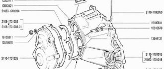
Preliminary calculation of gearbox shafts.
We will carry out preliminary calculations for torsion based on reduced permissible stresses.
Drive shaft:
The diameter of the output end at the permissible stress, taking into account the influence of shaft bending from belt tension, [τ 0 ]=25 MPa
We take the nearest larger value from the standard series d b2 = 28 mm. The diameter of the shaft under the bearings is taken d p2 = 35 mm. We will make the gear as one piece with the shaft.
Driven shaft:
The permissible stress is accepted [τ 0 ]=20 MPa
Taking into account the standard row d b3 = 50 mm. The diameter of the shaft under the bearings is assumed to be d p3 = 55 mm, under the gear wheel d k3 = 60 mm.
The diameters of the remaining sections of the shafts are determined based on design considerations when configuring the gearbox.
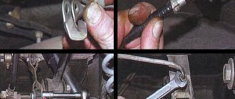
Manual transmission calculation - DRIVE2
Hi all. After writing an article on calculating a diesel transmission for my car, I receive a bunch of personal letters asking me to also calculate manual transmissions of other designations. In general, it’s not difficult for me, but it takes time, and you don’t always have time. In my article, everything seems to be clear and transparent, but no one wants to delve into it themselves. Therefore, in this article I will try to show how to make such a calculation yourself as quickly and simply as possible, using a special TABLE.
manual transmission calculation
You only need to enter data in the green field, the rest will be calculated automatically. It’s clear that you can’t do without the ETKA catalog data, so we’ll assume that it exists and is installed. For example, I will take the calculation of a 5-speed. Manual transmission EHV, which was installed on the 1.8T. First, we look for the data of the main pair of our box:
Full size
EHV 37/10
There we see the value “37/10”, and enter it into the table in the line “main pair”. Next, we look for the values for each gear of our EHV box
Full size
EHV
and similarly enter into the table according to the transfer, we get the following calculation:
EHV calculation
Next, go to THIS site to calculate the speed in different gears, and enter the values from the red column of our table on the site:
The table shows the speed in km/h at different speeds. If this data is not enough, then you can study the orange “Total” column
This column shows the total gear ratio for each gear of a particular gearbox. This will help you understand which box is generally longer or shorter. We compare these values of two different boxes, the smaller, the longer. That's all the calculations, it seems clear. If you have any comments or additions, I will be happy to add them to the article.
www.drive2.ru
Chain transmission. Design calculation in Excel.
If your computer does not have MS Excel, then in this case it can be fully replaced with the OOo Calc program from the Open Office package, which can be downloaded and installed for free.
We will do the calculation for a transmission with two sprockets, without special tensioning devices. You can see the roller chain transmission diagram in the figure located just below. Let's get started - turn on Excel and open a new file. Next, the process of creating a calculation program will be described in detail.
In cells with a light turquoise fill we will write the original data and data selected by the user from tables or refined (accepted) calculated data. In cells with a light yellow fill we read the calculation results. Cells with a pale green fill contain source data that is less susceptible to change. Blue font is the initial data, red font is the results of calculations, black font is intermediate and non-main results.
I remind you once again that in the notes to all cells of column D we place explanations of how and where all values in the file table are taken from or by what formulas are calculated.
Initial data (block 1):
1. the transmission efficiency (this is the efficiency of the chain transmission and the efficiency of two pairs of rolling bearings)
to cell D2: 0,921
2. We write down the preliminary value of the gear ratio u'
to cell D3: 3,150
The chain drive should be designed with gear ratios preferably no more than 7, in special cases no more than 10.
3.
the rotation speed of the small drive sprocket shaft
n1
in rpm
to cell D4: 120,0
The rotation speed of the high-speed transmission shaft must not exceed the values specified in the note to cell D 4!
4.
the rated drive power (shaft power of the smaller sprocket)
P1
in kW
to cell D5: 5,000
Calculation of chain transmission (block 1):
5. Determine the number of teeth of the driving small sprocket z 1
in cell D6: =OCRUP(31-2*D3;1) =25
z 1 =31-2* u ' rounded up to a whole number (preferably to an odd number, even better to a prime number)
6. Calculate the torque on the shaft of the small sprocket T1 in N*m
in cell D7: =30*D5/(PI()*D4)*1000 =397,9
T1 =30* P1 /( π * n1 )
7. Determine the number of teeth of the driven large sprocket z 2
in cell D8: =ROUND(D3*D6,0) =79
z 2 = z 1 * u ' rounded to the nearest whole number
The number of teeth on a large sprocket should not exceed 120!
8. We clarify the final gear ratio u
in cell D9: =D8/D6 =3,160
u = z 2 / z 1
9. We calculate the deviation of the final gear ratio from the preliminary delta in %
in cell D10: =(D9-D3)/D3*100 =0,32
delta =( u — u ' )/ u'
The deviation of the gear ratio should preferably not exceed 3% modulo!
10. the rotation frequency of the large sprocket shaft n2 in rpm
in cell D11: =D4/D9 =38,0
n2 = n1 / u
11.
The power on the shaft of the large sprocket
P2
in kW is determined
in cell D12: =D5*D2 =4.606
P2 = P1 * efficiency
12. Calculate the torque on the shaft of the large sprocket T2 in N*m
in cell D13: =30*D12/(PI()*D11)*1000 =1158,4
T2 =30* P2 /(3.14* n2 )
Initial data (block 2):
All coefficient values in this block are assigned in accordance with the recommendations given in the notes to the corresponding cells.
13. We assign a dynamic coefficient k d and write
to cell D14: 1,00
14. Select the transmission center distance coefficient k a and write down
to cell D15: 1,00
15. We assign the coefficient of inclination of the transmission axis to the horizon k n and write down
to cell D16: 1,00
16. Assign the chain tension adjustment coefficient k p and write down
to cell D17: 1,25
17. Select the chain lubrication method coefficient k cm and write down
to cell D18: 1,40
18. Select the transmission frequency coefficient k p and write down
to cell D19: 1,25
Calculation of chain transmission (block 2):
19. Calculate the coefficient of transmission operating conditions k e
in cell D20: =D14*D15*D16*D17*D18*D19 =2,19
k e = k d * k a * k n * k r * k cm * k p
Next, the user works with the program in a cycle in dialog mode.
20. We set the number of rows of the chain m and enter
21. We accept the preliminary permissible pressure in the chain joints (at z1 = 17) [ p '] in MPa
in cell D22: 27,0
This is approximately the average value for n 1 = 120 rpm according to the table in the note to cell D 22.
Read also: Manual bending machines for cold forging
22. Calculate the permissible pressure in the chain joints (at z1 =25) [ p ] in MPa
in cell D23: =IF(D21=1;D22*(1+0.01*(D6-17));D22*(1+0.01*(D6-17))*0.85) =29,2
with m =1: [ p ] = [ p '] *(1+0.01*( z 1 -17))
with m =2: [ p ] = [ p '] *(1+0.01*( z 1 -17))*0.85
23. Determine the calculated minimum chain pitch t
'
in mm
in cell D24: =2.8*(D7*1000*D20/D6/D21/D23)^(1/3) =29,704
t ' =2.8*( T 1 * k e /( z 1 * [ p ] * m ))^(1/3)
24. Select from the standard series given in the note to cell D25 the nearest larger value of the calculated chain pitch t
in mm and write it down
to cell D25: 31,750
21/2. We return to point 21 and write down the permissible pressure in the chain joints (at z1 =17) [ p '] in MPa, t = 31.750
to cell D22: 26,0
22/2. We read the new value of the permissible pressure in the chain joints (at z1 = 25) [ p ] in MPa
in cell D23: =IF(D21=1;D22*(1+0.01*(D6-17));D22*(1+0.01*(D6-17))*0.85) =28,1
23/2. We read the new value of the calculated minimum chain step t '
in mm
in cell D24: =2.8*(D7*1000*D20/D6/D21/D23)^(1/3) =30,080
The chain step t we selected in paragraph 24
remained greater than the calculated value
t '
.
This is good, otherwise we would have to select a new larger value of the chain step t
and repeat the return to
step 21 .
25. Based on the selected step, we determine from the table notes to cell D26 the projection area of the hinge of chain A
in mm2 and write
to cell D26: 262
26. Calculate the linear speed of the chain v
in m/s
in cell D27: =D6*D25*D4/60000 =1,6
v = z1 * t * n1 /60000
The linear speed of the chain should preferably not exceed 7 m/s for open gears!
27. Circumferential force Ft
in H we count
in cell D28: =D5*1000/D27 =3149,6
Ft = P 1 *1000/ v
28. Determine the design pressure in the chain joints p
in MPa
in cell D29: =D28*D20/D26 =26,3
p = Ft * k e / A
29. At this step, the program compares the calculated pressure in the chain joints p
with permissible pressure
[ p ]
and displays a summary
in merged cell B30C30D30E30: =IF(E29
. «) = Everything is fine :p
.
If
p > [ p ], then you need to return to step 20 and perform the calculation again, increasing the row or pitch of the chain.
If
p [ p ], then, as in our example, everything is fine, you can move on to the final block of chain transmission calculations
Calculation of chain transmission (block 3):
30. Calculate the minimum recommended center-to-center transmission distance a min in mm
in cell D31: =30*D25 =953
a min =30* t
31. Calculate the maximum recommended center-to-center transmission distance a max in mm
in cell D32: =50*D25 =1588
a max =50* t
The center distance of the chain drive should not exceed 80*
t !
32. From the range and design parameters defined above, we assign a preliminary center-to-center transmission distance a ' in mm and write
to cell D33: 1000
It is advisable to select the center distance
from the range: a min a a max
33. Calculate the estimated number of chain links Lt '
in cell D34: =2*D33/D25+0.5*(D6+D8)+(((D8-D6)/(2*PI()))^2)/(D33/ D25) =117,3
Lt' =2* a' / t +0.5*( z1 + z2 )+((( z2 – z1 )/(2*π))^2)/( a' / t )
34. Select the number of chain links Lt , rounding the value Lt ' to the nearest even integer value and write
to cell D35: 118
35. Calculate the final adjusted center-to-center distance of the chain drive a in mm, taking into account the required chain slack
in cell D36: =0.25*D25*(D35- (D6+D8)/2+((D35- (D6+D8)/2)^2-8*((D8-D6)/2/PI( ))^2)^0.5)*0.996 =1007
a =0.25* t *( Lt -0.5*( z1 + z2 )+(( Lt -0.5*( z1 + z2 ))^2-8*(( z2 – z1 )/(2* π))^2)^0.5)*0.996
36. Determine the pitch diameter of the leading small sprocket d 1
in cell D37: =D25/SIN (PI()/D6) =253,3
d 1 = t / sin ( π / z 1 )
37. Calculate the pitch diameter of the driven large sprocket d 2
in cell D38: =D25/SIN (PI()/D8) =798,6
d 2 = t / sin ( π / z 2 )
A design calculation in Excel for a chain drive with two sprockets without special tensioners has been completed. The main parameters and overall dimensions of the transmission are determined based on partially specified power and kinematic characteristics. The data obtained can be used for more detailed geometric calculations of sprockets and verification force calculations.
I always look forward to your feedback, questions, and comments on the article, dear readers.
I ask THOSE WHO RESPECT the author’s work to download the file AFTER SUBSCRIBING to article announcements.
File download link: raschet-tsepnoy-peredachi (xls 55.5KB).
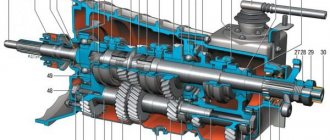
Classification of gears . Drive roller chains are distinguished (Fig. 77): single-row normal (PR), single-row long-link lightweight (LRD), single-row reinforced (PRU), two-row (2PR), three-row (ZPR), and four-row (4PR) and with curved plates ( AT).
Fig.77. Types of drive chains: a – single-row bushing, b – single-row roller, c – double-row roller, d – roller with curved plates, e – gear, f – shaped hook hook, g – shaped pin chain.
Purpose. Chain transmissions refer to mechanical gear transmissions with a flexible connection and are used to transmit rotary rotation between shafts located at considerable distances and, if necessary, to ensure a constant gear ratio. The chain drive consists of sprockets located coaxially at some distance from each other, and a chain enclosing them. The rotation of the drive sprocket is converted into rotation of the driven sprocket due to the engagement of the chain with the sprocket teeth. Because chains stretch as they wear, the chain tensioner must adjust the chain tension. This regulation, by analogy with belt drives, is carried out either by moving the shaft of one of the sprockets, or using adjusting sprockets or rollers.
Advantages. Thanks to the engagement, there is no slipping of the traction element. Possibility of transmitting motion between shafts over long distances (up to 8M). Smaller dimensions than belt drives, especially in width. Less load on transmission shaft supports. Possibility of transmitting rotation to several shafts with one chain. Greater efficiency.
Flaws. Increased noise and vibration due to the impact of chain links on sprockets, which increase with increasing chain speed. Increase in chain pitch during operation due to wear. The need for devices for tensioning chains. The lack of fluid friction in the hinges increases their wear, so periodic or constant lubrication is necessary. The chain speed is uneven, especially with small numbers of sprocket teeth, which creates additional dynamic loads and fluctuations in the gear ratio.
Areas of application. Chain drives are used in transport, agricultural, road construction, mining and oil machinery, as well as in metal-cutting machines.
In terms of transmission power, they are used at 100 kW, (in some transmissions up to 3000 kW), in terms of peripheral speed - 15 M/s, in terms of gear ratios - 7, efficiency of chain transmissions - 0.94...0.97.
Geometric calculation. The centers of the chain hinges when engaged with the sprocket teeth are located on the pitch circle of the sprockets, which is determined
, (13.1)
Where P – Chain pitch; – Number of sprocket teeth.
For drive chains, the teeth of the sprockets determine all the dimensions of the teeth, as well as the diameter of the tops and bottoms of the teeth of these sprockets (Fig. 78).
The minimum center-to-axle distance Atіp of the chain drive is taken depending on the gear ratio And the gear and the condition that the angle of the chain wrapping the smaller sprocket is at least 120°, i.e. at And Calculation of the chain drive – 3.3 out of 5 based on 11 votes
Any movable connection that transmits force and changes the direction of movement has its own technical characteristics. The main criterion that determines the change in angular velocity and direction of movement is the gear ratio. Inextricably linked with it is a change in force—the gear ratio. It is calculated for each transmission: belt, chain, gear when designing mechanisms and machines.
Read also: Combined wood cutters for a manual router
Before you find out the gear ratio, you need to count the number of teeth on the gears. Then divide their number on the driven wheel by the same indicator on the drive gear. A number greater than 1 means an overdrive gear, increasing the number of revolutions and speed. If less than 1, then the transmission is downshifting, increasing power and impact force.
Gearbox and main gear calculator
| R wheels | |
| Wheel width | |
| Profile | |
| Engine speed | 500100015002000250030003500400045005000550060006500700075008000850090009500100001050011000 |
| Main couple | 3.9 3.5 3.74.14.34.54.74.95.16.8 |
| 1st gear | 3.63 (std.) 2.92 (5th row)2.92 (6th row) 2.92 (7th row)3.42 (8th row) 3.42 (10th row)3.63 (11th row) 3.16 (12 - row) 3.17 (15th row) 3.17 (18th row) 3.17 (20th row) 3.17 (102nd row) 2.92 (103rd row) 2.92 (104th row) 2.92 (200- 1st row)3.0 (026th row) 3.0 (711th row) 2.67 (745th row)2.67 (74th row) |
| 2nd gear | 1.95 (std.)1.81 (5th row)1.81 (6th row)2.05 (7th row)2.05 (8th row)2.05 (10th row)2.22 (11th row)1.95 (12 - row)1.81 (15th row)2.11 (18th row)1.9 (20th row)1.95 (102nd row)1.95 (103rd row)1.95 (104th row)2.22 (200- 1st row)2.53 (026th row) 2.53 (711th row) 1.93 (745th row)1.93 (74th row) |
| 3rd gear | 1.36 (std.)1.28 (5th row)1.28 (6th row)1.56 (7th row)1.36 (8th row)1.36 (10th row)1.54 (11th row)1.36 (12 1st row)1.28 (15th row)1.48 (18th row)1.26 (20th row)1.36 (102nd row)1.36 (103rd row)1.36 (104th row)1.76 (200- th row)2.06 (026th row) 2.06 (711th row) 1.59 (745th row)1.56 (74th row) |
| 4th gear | 0.94 (std.)0.97 (5th row)1.06 (6th row)1.31 (7th row)0.97 (8th row)0.97 (10th row)1.17 (11th row)1.03 (12 - row)0.94 (15th row)1.13 (18th row)0.94 (20th row)0.94 (102nd row)0.94 (103rd row)1.03 (104th row)1.39 (200- 1st row)1.74 (026th row) 1.74 (711th row) 1.37 (745th row)1.37 (74th row) |
| 5th gear | 0.78 (std.)0.78 (5th row)0.94 (6th row)1.13 (7th row)0.78 (8th row)0.78 (10th row)0.89 (11th row)0.78 (12 - row)0.73 (15th row)0.89 (18th row)0.73 (20th row)0.73 (102nd row)0.69 (103rd row)0.73 (104th row)1.17 (200- 1st row)1.48 (026th row) 1.48 (711th row) 1.2 (745th row)0.79 (74th row) |
| 6th gear | no0.69 (std.)0.94 (7th row)0.78 (18th row)0.94 (200th row) |
| Results: | |
martaler.ru