Sensor types
There are two types of sensors on cars:
- passive sensor built on the basis of a coil;
- active sensor that uses the Hall effect.
The passive sensor turns on after the start of movement and reads data from the toothed pulse ring. The passage of a tooth past the device causes the generation of a current pulse, which is read by the control unit. The sensors start working at speeds above 5 km/h and do not respond to contamination.
The active sensor consists of electronic components and a permanent magnet, which is mounted on the hub. When the magnet rotates in the device, a potential difference arises, which is formed into a microcircuit control signal. The information is then sent to the block. Sensors of this design are rare and cannot be repaired.
Anti-lock braking system (ABS). Description
A car's Anti-lock Braking System is a system that regulates the brake fluid pressure in the brake circuits, which helps prevent the wheels from locking during braking. In other words, this system prevents skidding, which provides the following benefits:
- Increasing vehicle stability.
- Reducing braking distance.
- Saving rubber and preserving the studs on car tires.
In addition to its primary function, anti-lock braking system sensors and valves are used for many other vehicle systems. For example, exchange rate stability system or emergency braking assistance system. The stability control system brakes certain wheels during sharp turns or drifts, which significantly improves safety performance. Brake Assist keeps the brake pedal depressed until the vehicle comes to a complete stop.
Varieties of design
To calculate the angular speed of wheel rotation, 2 types of ABS sensor devices can be used:
- based on an inductive element. They are also called passive, since the sensitive element does not require external power, and the operating principle itself is based on the effect of electromagnetic induction. Despite the simplicity of design and reliability, such devices are becoming less and less common on modern cars. The main drawback of the design is that at low vehicle speeds it is impossible to adequately calculate the wheel speed;
- sensors based on the Hall effect. They are also called active, since the sensitive element needs power - a reference voltage. The signal produced by such speed sensors allows the ECU to more accurately calculate the wheel speed.
ABS device
Sensors that record the wheel speed send this data to the control unit. The unit then processes the received information and controls the operation of the valve actuator unit, which is connected to the brake system. Using magnetic valves, the fluid pressure in the brake circuits is regulated.
You may be interested in: Kia X Line car: reviews from the first owners
In the process of reducing speed, the data is processed electronically, and the operation of the system is adjusted according to the development of the situation on the road and the quality of the road surface.
Modern cars are equipped with the most effective four-channel ABS systems. Here there are sensors near each wheel, and rotation adjustment can be carried out for each wheel separately. This is very convenient on difficult roads, when each wheel may have a different surface. Three-channel systems consist of three sensors, two of which are located on the front wheels and one on the rear pair.
The cheaper, simpler, but no less effective two-channel system operates on the basis of two sensors. One is installed near the front wheel, the second - near the rear wheel diagonally. The system works clearly and smoothly. Problems with it rarely happen, as owner reviews say.
How the anti-lock braking system works
How to diagnose ABS yourself? — to answer this question with confidence, it is important to know the structure of the system itself. To do this, let’s look at several individual parts of it:
- Speed sensors. Sensors are located near each wheel of the car. They transmit information about the rotation speed of each wheel to the ABS control unit.
- ABS control unit. The control unit receives signals from speed sensors, analyzes the situation, and, in the event of a wheel lock, transmits a command to the hydraulic control unit.
- The hydraulic control unit, having received a signal about a blocked wheel, closes the brake fluid channel going to this wheel.
The result is that as soon as the wheel is locked, the system “releases” it. Once this happens, it is blocked again. All this happens with high frequency, and as a result, the wheels rotate at maximum effort, but without switching to skidding.
Operating principles of the system
There is a widespread belief that the main task of the anti-lock braking system is to shorten the braking distance. But for this there are modern pads and smart systems. The purpose of ABS is to maintain controllability while reducing speed. When the wheels do not rotate and are blocked, and the car continues to move under the influence of inertia, it is no longer possible to influence the trajectory in any way. The car will slide on locked wheels as it pleases. When the wheels are locked, the situation on the road turns into a bowling alley.
You may be interested in: Do-it-yourself fiberglass bumper: technique, necessary materials and tools, step-by-step operating instructions and expert advice
In order to avoid such problems, the ABS system was developed. The electronic unit together with sensors does not allow the brake mechanism to completely block the wheel. The wheels rotate intermittently. A second to turn, another second to block. This mode not only provides very effective braking, but also controllability. As long as the wheels are spinning, the car will respond correctly to steering inputs.
Common breakdowns
A slight cracking sound when pressing on the brake pedal is quite normal. This sound occurs due to the functioning of modulators. If the ABS is faulty, its indicator lights up and does not go out even when the engine is running. There are several most common malfunctions of the anti-lock braking system:
- Deactivation based on self-diagnosis results. This may be caused by a malfunction of the control unit or damage to the ABS touch sensor wiring.
- After activation, ABS self-diagnoses, but then turns off. This problem can be caused by broken wires, broken contacts or their oxidation, where the supply of power and signals is disrupted.
- An error appears, but the ABC sensor works. This is a consequence of a break in the touch sensor. It can also be caused by differences in tire pressure or even different tread patterns.
- Complete loss of system functionality. There can be a lot of reasons for this, ranging from sensor breakdowns to wear of the wheel bearings.
To identify a malfunction, you need to check the pressure and play in the tires, the performance of the comb and rotor. If the elements have chips, then it is better to completely replace them. If the problem remains unresolved, then the reason most likely lies in the electronic component. In this case, you need to get a diagnostic code.
Causes and symptoms of malfunctions
- As I already said, the corresponding indicator lights up on the panel; this can happen while driving, braking, or when turning the key in the ignition. In the latter case, the appearance of the inscription indicates self-diagnosis of the system; after you start the engine, the light should go out.
- If the ABS system malfunctions during braking, you will not hear the characteristic sound of the ABS unit located under the hood and will not feel the vibration that occurs when you sharply press the brake pedal and try to slip the wheels.
In new generation cars, when the ignition is turned on, automatic self-diagnosis of the anti-lock braking system occurs, during which the performance of all its elements is assessed.
| Signs | Possible reasons |
| Self-diagnosis shows an error. ABS is disabled. | Incorrect operation of the control unit. Broken wire from the sensor to the control unit. |
| Diagnostics does not detect errors. ABS is disabled. | Violation of the integrity of the wiring from the control unit to the sensor (break, short circuit, oxidation). |
| Self-diagnosis gives an error. ABS works without turning off. | Broken wire of one of the sensors. |
| ABS does not turn on. | Break in the power supply wire of the control unit. Chips and fractures of the impulse ring. Large play on a worn hub bearing. |
In addition to the display of indicator lights on the dashboard, there are the following signs of a malfunction of the ABS system:
- When applying pressure to the brake pedal, there is no reverse knocking or vibration of the pedal;
- During emergency braking, all wheels are blocked;
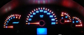
- The speedometer needle shows a speed less than the actual speed or does not move at all;
- If more than two gauges fail, the parking brake indicator on the dashboard lights up.
In the event of a malfunction of the anti-lock braking system, a warning lamp lights up on the instrument panel
The reasons for the ineffective operation of the ABS may be:
- Failure of one or more speed sensors;
- Damage to sensor wiring, which results in unstable signal transmission to the control module;
- A voltage drop at the battery terminals below 10.5 V disables the ABS system.
Self-diagnosis of ABS
Important: The brake controller de-energizes the valve relay when a diagnostic trouble code is detected. The scan tool in Data List mode displays that the valve relay is de-energized. This condition is not a malfunction.
Important: For safety reasons, it is recommended not to drive the vehicle with diagnostic equipment connected. An exception is a trip to check the speed of rotation of the wheels, provided that the requirements for the test are met.
The brake system controller has a self-diagnostic function and can independently detect, and in many cases isolate, system faults. If a malfunction is detected, the brake system controller enters a code corresponding to this malfunction, turns on the ABS warning lamp and/or the EBD warning lamp, and, if necessary, turns off the ABS and/or EBD for the duration of the current ignition cycle. At each ignition cycle, the brake controller performs a self-test if the vehicle speed is > 6 km/h and the brake pedal is not depressed, or if the vehicle speed is > 15 km/h and the brake pedal is depressed. During self-diagnosis, the operation of all solenoid valves, electric pump and relays is checked by turning them on/off. If a malfunction is detected, the corresponding diagnostic code will be entered into the controller's memory.
DIY ABS diagnostics
The very first sign of a malfunctioning ABS system is a light on the dashboard. After it lights up, it is important to immediately make a diagnosis. Let's consider the actions that need to be taken if the ABS malfunctions:
- Check the fuses and relays of the anti-lock braking system control unit.
- Compare the tire pressure - it should be the same everywhere.
- Examine the rotor of each sensor for contamination.
- Use a tester to measure the resistance in each of the sensors with the ignition on. Lift the wheel on a jack and rotate it and observe the changes.
- Check the integrity of the wires coming from the sensors to the control unit.
- Check the integrity of the wires going to the ABS hydraulic unit.
The best diagnostic option would be to check by connecting a laptop or smartphone to the diagnostic connector - this will save a lot of time and instantly determine the cause of the breakdown.
Checking the voltage on the sensor winding
Before starting the testing procedure, it is advisable to know the standard resistance value of the ABS sensors installed in your car. This information can be found either on the manufacturer's website or on the Internet. The algorithm for checking the sensor resistance is quite simple:
Advice! Typically, the resistance of passive induction sensors is in the range of 700÷2500 Ohms. If you are unable to find technical information about specific sensors installed in the car, you will have to check the resistance of all ABS sensors. Their simultaneous failure is unlikely. By comparing the results of all measurements taken, it will be possible to draw a conclusion about which specific sensor is “buggy” and replace only that one.
You can check the resistance of all sensors without removing the wheels. For this:
- We find the ABS control unit under the hood of the car.
- We disconnect from it the connector in which the wires from the sensors and other devices included in the anti-lock brake system are fixed.
- Next, we connect the multimeter probes to the corresponding contacts (to which the sensors are directly connected) and sequentially check the resistance of all sensors. The pinout of the connector can be found in the operating instructions or on the manufacturer's website.
On a note! This test method allows you to determine not only the resistance of the sensor coil, but also the serviceability of the wiring from the sensor itself to the control unit.
Another way to check the performance of ABS sensors is to measure the output voltage that appears on the winding when the wheel rotates. To do this we do the following:
- We hang the wheel using a jack and remove it.
- We find the ABS sensor and disconnect its connector from the wiring leading to the control unit.
- We switch the multimeter to AC voltage measurement mode.
- We connect the probes to the contacts of the sensor connector.
- Rotate the wheel hub (at a speed of 1÷2 rpm).
- If there is a voltage of 200÷1700 mV (its value varies depending on the specific sensor model), it can be stated that the sensor is working. There's no reason to worry. If you were unable to find the technical specifications of the sensor, it is worth checking all ABS sensors installed on the car in a similar way. If, as a result of testing, a low voltage is detected on one of them (compared to the others), this indicates that it is not operating correctly.
On a note! If, when measuring the resistance of all sensors, the ohmmeter readings indicate their performance, but when the wheel rotates, a low voltage (or absence) appears on the sensor windings, then this may be a consequence of wear or breakage of the gear wheel.
Clearing Diagnostic Codes
Necessary equipment
Scan ToolDiagnostic codes can be cleared from the brake controller memory as follows:
- Select the "Clear DTCs" command on the scan tool.
Detailed instructions are provided below. Once clearing is complete, verify that the system is functioning normally and that there are no codes present. The controller will not allow codes to be cleared until all codes have been reviewed. Diagnostic codes cannot be cleared by turning off the controller, power to the battery, or turning the ignition switch to the LOCK position.
Checking the sensor without instruments
The most crude way to check the health of the sensor is to test the magnetic field created during operation of the device. To do this, a steel object is applied to the sensor, which should be attracted when the ignition is turned on.
It is possible to visually inspect the device for cracks in the housing or noticeable breaks and oxidation in the wiring. It is recommended to inspect the plug and the condition of the contacts in it; oxidation is the cause of deterioration in signal conductivity.
How to use a tester to check the ABS sensor for functionality
Its performance can be checked using a multimeter. To do this, you need to move the multimeter to the “diode” position. Why? Most ABS sensors in the circuit have protection in the form of a diode connected in series with the circuit. That is, a regular call can lead to incorrect information.
It must be “ringed” in both directions. Typically, the resistance of the ABS sensor ranges from several hundred ohms to 2 kiloohms.
However, testing the sensor directly from its connector does not provide complete information about the passage of its signal to the ABS unit.
In many cases, the cable connecting the sensor connector to the ABS unit is damaged. Such malfunctions are especially common for rear wheel ABS sensors, since the cable length can be more than 3 meters, and manufacturers do not always design its routing correctly.
During the repair of ABS systems, there are cases of up to three fractures or rubbing of the anti-lock braking system sensor cables.
In order to check the sensor from the ABS control unit, you need to find the pinout (connection) of the connector in reference books or on the Internet. Next, you should disconnect the connector from the block and ring the ABS sensors directly from the connector contacts.
We remind you once again that the type of ABS connector and sensor contacts will be different for each car model; reference data should be used. ABS blocks (they can be easily found under the hood by the large number of brake pipes that go with them) are usually marked with their classification, for example BOSCH 5.2.
If, as a result of checking with a multimeter, the ABS sensor rings in one or both directions, this is not evidence of its serviceability.
Structurally, it is made in the form of an inductance coil placed in a magnetic core. The coil has a large number (up to several thousand) turns of very thin insulated wire.
Often moisture gets inside the sensor, and this is very likely, since it is located in the most corrosion-prone area in the immediate vicinity of the wheels. Water, especially saline solution, can cause interturn short circuits. In this case, the winding resistance will change slightly, but the quality factor drops tens of times. This leads to a decrease in the signal level of the ABS sensor and its inoperability.
Very often during operation, especially after replacing hub and wheel elements, the ABS fault light starts to light up. Computer diagnostics show a lack of signal from the ABS sensor, for example, the right front wheel.
The owner replaces it based on diagnostic readings, but the ABS system remains faulty. Sometimes, after removing the error with the scanner, the malfunction light goes out, but as soon as you drive a few hundred meters, make a couple of brakes, it lights up again.
The issue here is not the sensor, but the design features of the signal formation (induction) of the wheel rotation sensor.
How to check the ABS sensor with a tester
So, your ABS light comes on on the instrument panel , what should you do? First of all, it is important to understand that this type of sensor is checked according to two parameters:
- Resistance;
- Voltage.
At specialized stations, the ABS sensor is checked by connecting an oscilloscope . In this case, the wheels are turned manually, and a sine wave is visible on the device screen. It shows the dependence of the signal frequency on the power of oscillatory pulses. Sometimes some craftsmen take measurements using the Ts-20 .
On it, the inspector can see deviations of the needle, and if the device is digital, then an increase in the voltage value. Diagram of the ABS sensor signal on an oscilloscope
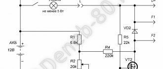
At home, to test the ABS sensor, you can make a special device, which will consist of a resistor from 900 Ohm to 1.2 kOhm , as well as a pair of wires. At the ends of the wires you need to place clamps that can be connected to the contact group of the sensor itself.
After this, you need to check each wheel. Turn the wheels one way and then the other. At the same time, connect our resistance to the sensors, turn on the ignition and observe the behavior of the instrument panel warning light. In cases where the light goes out when the resistance is connected, the sensor can be considered faulty. Agree, this method is very interesting, but labor-intensive, so let’s move on.
To check the ABS sensor with a tester , you will need any modern multimeter. First of all, we measure the resistance, which can be different for each car and its sensor. That is why you first need to find the standard resistance readings for your car. The bulk of ABS sensors fit into the range from 1.2 to 1.8 kOhm . When the tester is connected to the sensor and is measuring resistance, try shaking the wires going to the sensor itself. In this case, the instrument readings should not deviate, and if this happens, then there is an open circuit.
Checking the ABS sensor
After these measurements, disconnect the contacts of the multitester and switch it to voltage measurement mode . Now you need to spin the car wheel to about 40-50 rpm . Next, we monitor the readings of the sensor that will produce voltage. On all sensors it is equal to 2 volts.
Of course, under ideal conditions, you need to check the sensor by connecting special software, which can indicate more accurate parameters of the ABS operation and its malfunctions.
Multimeter test method
If you know how to use a multimeter, then you can check the passive ABS sensor using even the cheapest universal meter. Correspondence of possible faults and methods for their diagnosis:
- open circuit of the coil winding. Set the multimeter to diode testing mode. If the device shows infinite resistance, then there is an open circuit in the circuit;
- unsoldering the coil winding contacts. The nature of the failure is the same as in the case of a break;
- short circuit. To check, switch the multimeter to resistance measurement mode - ohmmeter, measurement range - up to 20 kOhm. Pre-measure the resistance of a previously working sensor or find out the standard value from the technical documentation. Typically, the resistance of serviceable elements ranges from 0.7 to 2.5 kOhm. It is important to take into account that the resistance of working sensors on the front and rear axles can differ significantly.
If the ABS sensor is removed from the car, then you can simulate the rotation of the master disk with any magnetic metal object.
Due to the aggressiveness of the installation environment, ABS sensors on motorcycles may have an electromagnet instead of a permanent magnet, which must be taken into account when checking without dismantling (the ignition must be on).
How to make your search easier
In order not to carry out testing with a tester on each wheel separately, remove the connector of the ABS control unit. The video shows that once you understand the pinout, you can quickly find which circuit has a short circuit or an open circuit.
ABS braking system: guarding vehicle safety during emergency braking
If any problems occur in the operation of the vehicle, the driver is faced with certain problems. These can be both serious breakdowns and minor faults that allow the car to be used in the future. Now we will talk about what the ABS sensor is, where it is located and how it is checked.
Diagram of the ABS system with the location of all components
ABS or anti-lock braking system is a system designed to prevent a vehicle's wheels from locking during braking.
The main purpose of this unit is to maintain vehicle stability and controllability. As practice shows, braking distances with an ABS system are almost always shorter than without it.
Today, the unit is one of the most complex braking systems; ABS may include:
- traction control system;
- electronic vehicle stability control unit;
- emergency braking assistance mechanism.
In general, the system includes a control unit, a hydraulic device, wheel brake elements, as well as speed sensors.
As you might guess, the main component of any system is a block designed to receive pulses from wheel speed sensors and evaluate their performance.
The information received by the unit is fully checked by the system, as a result the device determines the degree of wheel slip. The received data is transmitted in the form of signals to the valves of the valve body designed to control the device.
Where is?
Sensor installation location on the rear wheel
The electronic unit itself can be located anywhere - everything here depends solely on the manufacturer. As for the wheel speed sensor, the ABS sensor is located on the wheel hub. Its performance and resistance can be determined with a special tester - a multimeter, but we will talk about this later.
How does it work?
The brake cylinder transmits pressure to apply pressure to the brake calipers. As a result of this force, the pads begin to press directly against the discs.
Regardless of how hard the driver applies the brake, this pressure should always remain at the optimal level. The key advantage of any ABS system is that, as a result of analyzing the rotation speed of each wheel, it automatically selects the required pressure level.
Accordingly, it prevents the wheels from locking, and during full braking, the system automatically regulates the pressure in the system.
Actually, this is the principle of the system’s performance.
If the vehicle is equipped with all-wheel drive or rear-wheel drive, there will be only one ABS sensor - this regulator is installed on the rear axle differential.
Data on the speed of rotation or blocking is transmitted from the nearest wheel, usually the right one, at the same time an impulse about what the pressure should be is transmitted to all wheels of the car.
Diagnostics of the ABS system using a tester
As for operating modes, there may be several of them.
The mechanism, which is controlled by magnetic valves, regardless of the manufacturer and brand of the vehicle, operates in several modes:
- When the inlet valve is open and the outlet valve is closed, the assembly will not prevent the pressure level from increasing.
- A corresponding impulse is transmitted to the inlet element, and the component will be closed; the pressure level in this case remains unchanged.
- Another mode - a signal about a decrease in pressure level is transmitted to the outlet component, and accordingly, the valve begins to open. At this time, the inlet component closes, the pressure level begins to drop as the check valve comes into operation.
As a result of the fact that the system operates in such modes, the process of increasing the pressure level is carried out in a stepwise manner.
If any malfunctions occur, for example, in the operation of the front right speed sensor, the device simply goes back to work. In the future, the braking system functions without the participation of ABS.
By the way, if the system or the front right wheel speed control fails, a signal will appear on the instrument panel warning the driver about a malfunction of the unit (the author of the video is Yakov Sokolov).
Sensor check
How to check the ABS sensor yourself? The need to remove and repair the wheel speed regulator arises when it fails, but the car owner is not always able to determine the breakdown.
If the wheel speed sensor does not work correctly or is faulty, it will no longer be able to transmit all the necessary information to the control unit. Accordingly, the ABS unit will not be able to perform the functions assigned to it, that is, when you try to brake the car, the wheels will lock.
If you notice that indicators or a corresponding inscription appear on the control panel, you need to remove and repair the regulator yourself or contact a service center.
The front wheel speed control is an induction device that operates in tandem with a toothed metal pulley located on the hub.
As a rule, the need to remove and repair the front or rear sensor occurs in the event of a wiring break - this problem is one of the most common. Therefore, it is quite possible to determine such a breakdown with your own hands by measuring the resistance - for this you need to use a tester.
The tester itself is connected to the corresponding connectors of the front sensor, after which the resistance level is measured (the author of the video is Resta).
It should be noted that the resistance indicator must be within certain limits. These limits are indicated in the vehicle's service book and they may vary depending on the make of the car.
If during diagnostics it turns out that the resistance indicator tends to zero when measured with your own hands, this indicates that there is a short circuit in the system. You can solve this problem with your own hands - just remove the sensor and get rid of the short circuit.
If the resistance tends to infinity, as the tester will tell you, then this indicates that there are breaks in the wiring; in this case, you need to remove the device and repair the circuit by removing the breaks.
The next step in diagnosing the regulator yourself is to check the wheel and resistance level. If the resistance indicator changes, this indicates that the regulator is fully operational. If breaks are detected, it is necessary to remove the element and repair the circuit, ridding the system of breaks.
Repair of breaks is carried out exclusively by soldering; any twists must be excluded, since they will contribute to the formation of new breaks, oxidation, etc.
Please note that each component is marked with a specific marking, the colors of the wires are different, as is their polarity; this information must be used as a guide during the diagnostic process yourself.
If the device fails, it must first be removed. How to remove the regulator with your own hands - read the service book for the operation of your vehicle.
Once you can remove the element, you need to repair it. If the sensor cannot be repaired, it simply needs to be replaced with a new one.
When buying a device, you need to choose the best quality option so as not to face the need to repair it in the future.
Diagnostics of the ABS sensor with a multimeter
If you need to fully check the functionality of all devices, then you will not only have to diagnose all the contacts of the regulator yourself.
To obtain more accurate data, it is necessary to test the entire electrical circuit.
As practice shows, sometimes removing and repairing a device is not enough, since very often the cause of breakdown or malfunction is a violation of the integrity of the circuit.
If the regulator operates in normal mode and there are no problems with its operation, the tester will produce the following test results:
- the front right regulator will show resistance from 7 to 25 Ohms;
- the insulation resistance indicator will be more than 20 kOhm;
- the resistance level on the rear right regulator will be from 6 to 25 ohms.
It is also necessary to take into account that many modern vehicles are equipped with a self-diagnosis system. When checking the functionality of components in this way, combinations of errors will appear on the dashboard, which can later be deciphered using the service manual.
Possible faults
Now let's move on to the most common malfunctions characteristic of the operation of the device.
Let us note right away that if you hear a crackling noise while pressing the brake, then you should not sound the alarm - this is a normal condition characteristic of modulators.
If errors or breakdowns are detected in the operation of the system, the LED lamp will light up on the dashboard and will remain on after the engine starts (the author of the video is AUTO repair/NA/knee).
As for the breakdowns themselves, ABS is characterized by certain malfunctions:
- First of all, during self-diagnosis of the control unit, the system detects an error, while disabling the ABS system. As practice shows, usually in this case the reasons lie in the functioning of the controller unit. The problem may also appear as a result of breaks in the electrical circuit of the device, either front or rear, or both at once. The control unit will no longer receive impulses to measure angular velocities.
- Another malfunction is that the ABS system, after activation, successfully performs a self-test and then turns off. In this case, the reason is a break in the electrical circuit, oxidation of the regulator contacts, or a poor connection. In addition, the problem may occur as a result of breaks in the power wiring or a short circuit of the regulator to ground.
- Another breakdown - after activating the ABS unit, it checks and detects one or another malfunction, but continues to function. As a rule, this happens when breaks occur in one or more regulators. All necessary data on angular velocity is transmitted from additional devices. As practice shows, in this case the reason lies in the different range of tire pressure levels, as well as different tread patterns. In the event that one of the wheels is flat, or the tread on one of the wheels is rougher than on the others, then there is a possibility that the wheel itself slows down while driving. A similar situation will arise if you put tires on a vehicle from different cars, that is, its degree of wear will be different.
- For certain reasons, the system simply does not work. This may be a break in the electrical circuit, oxidation of the regulator contacts, failure of the bearings, or the presence of gaps or backlashes.
To solve the problem, first of all you need to check the presence of gaps, the level of pressure in the wheels, and the functionality of the sensors. You should also check the electrical circuit; if this does not help, then most likely the problem lies in the electronics.
“How to check the ABS system”
Using the example of a Honda Civic car, you can familiarize yourself with the process of diagnosing the ABS system and the procedure for resetting errors (the author of the video is Denis Azov).
Sorry, there are no surveys available at this time.
Source: https://labavto.com/elektronika/sensor/datchik-abs/
ABS Diagnostic Circuit Check
| Step | Operation | Values | Yes | No |
| 1 |
Is the scan tool reading data from the brake controller? | — | Go to Step 2 | Go to Step 6 |
| 2 | Check the meter readings. Are any current fault codes displayed? | — | See corresponding code table | Go to Step 3 |
| 3 |
Does the warning light come on for 4 seconds and then go off? | — | Go to Step 5 | Go to Step 4 |
| 4 | Check the condition of the ABS warning light. Does the ABS warning light stay on and stay on? | — | See “ABS warning light stays on” | See “ABS warning lamp faulty“ |
| 5 |
Does the warning light come on for 4 seconds and then go off? | — | Go to Step 12 | See "EBD warning lamp faulty" |
| 6 |
Is the voltage on all pins within the specified range? | 11-14 V | Go to Step 7 | See "Controller Power, No Diagnostic Codes" |
| 7 |
Does the measured resistance match that shown in the table? | ≈ 0 Ohm | Go to Step 9 | Go to Step 8 |
| 8 | Repair the open in the BLK and BLK/WH wires that failed the test. Is the repair complete? | — | The system is working properly | — |
| 9 | Using a digital voltmeter, measure the resistance between pin 11 of the brake controller connector and pin 12 of the diagnostic connector. Is the measured resistance less than that shown in the table? | 2 ohm | Go to Step 10 | Go to Step 11 |
| 10 | Replace the ABS unit. Is the repair complete? | — | The system is working properly | — |
| 11 | Repair open or high resistance in the BLS circuit between pin 11 of the brake controller connector and pin 12 of the diagnostic block. Is the repair complete? | — | Go to Step 1 | — |
| 12 | Test the vehicle while driving on the road as described above. Are any fault codes stored? | — | See corresponding code table | — |
Need for replacement
Any system malfunction will definitely be diagnosed - ABS has built-in diagnostics. It is triggered before each engine start. If the system is working normally, this indicator will light up when the engine starts, and then go out after half a minute.
But if the controller does not work correctly, then when the engine is running, the indicator will be constantly on or will blink while driving. This is one of the first signs that one of the sensors is faulty.
In addition, if the sensor or sensors are faulty, the on-board computer may generate errors; during sharp braking, the wheels may lock, and there may be a characteristic vibration on the pedal when braking. When the handbrake is off, the parking brake light may come on.
If your car has at least one of the problems described, then you need to carry out a competent and complete diagnosis. If it is discovered that the sensor has failed, then it needs to be replaced with a new one.
However, before replacing the front ABS sensor, you can try checking the gaps between the sensor and the ring and the tire pressure. You can diagnose and visually check the entire electrical circuit. If no obvious faults are found, then the problem is in the sensors or electronic systems.
Alternative verification method
When you don't have a multimeter at hand, you can check the ABS sensor in a simpler way. It will work when only one element fails, and not several. Diagnostics is performed as follows:
- Disconnect the connector on one wheel sensor. Next, you need to start the engine and drive a few meters.
- If the second light on the brake system (or handbrake) malfunctions comes on, then the element being tested is operational. Connect the block and repeat the operation on the next wheel.
- If one sensor is broken, the ABS indicator lights up, and if there are two or more sensors, the handbrake lamp lights up. When the second indicator on the panel does not light up, it means that you have disconnected the faulty element.
The method allows you to determine the location of the problem, but not its nature. For a more accurate diagnosis, you need to use a tester with an ohmmeter.
The presence of ABS in a vehicle greatly increases traffic safety. Gradually, car parts wear out and may become unusable. Knowing how to check the ABS sensor, the driver can identify and fix the fault in a timely manner without resorting to the services of a workshop specialist.
ABS sensor repair
If a faulty ABS sensor is detected, it is dismantled, after which the issue of replacement or repair is decided. The cost of the device is quite high, and often there is a long wait for its delivery, which makes repairs quite feasible. The work is performed in the following order:
1. The sensor is disassembled by cutting off the part in which the measuring coil is located with a hacksaw. The body is carefully filed in a circle so as not to damage the fasteners.
2. The plastic casing protecting the coil is removed using a sharp knife and the winding is unwinded from the frame.
3. Wind a new coil with a wire of the same diameter. The RES-8 relay winding is suitable for this. The number of windings must provide the required resistance value - 0.92-1.22 kOhm. The work is carried out very carefully, since the wire is quite thin, and if it breaks, the process begins again.
4. The ends of the wires are soldered to the terminals, and the coil is effectively insulated from moisture using silicone or wax sealant.
5. The sensor is assembled by restoring the old housing. If the shell is critically damaged, it is made independently from the body of an electrolytic capacitor, suitable in size, and epoxy glue. A hole is made at the bottom of the body for the coil rod. After placing the updated part there, glue is poured.
6. After the glue has dried, the capacitor shell is removed, and the sensor mount is glued to its original place.
7. After the repair is completed, the sensor body is ground with sandpaper to accurately fit the socket. During the installation process, observe the following rules:
- The core of the device is placed parallel to the teeth of the response disk and is controlled so that it does not overlap a pair of adjacent teeth;
- A gap of 0.9-1.1 mm is left between the tooth and the core.
At the end of the installation, check the functionality of the system by starting the engine and making sure that the ABS indicator goes out 6 seconds after the start.
How to change ABS sensors?
Often on modern cars they are installed on all four wheels. Removal of the front axle elements is carried out from the bottom or, on some models, from under the hood. But when replacing the rear ABS sensor, access is only available from below.
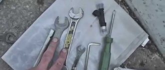
For the work you will need a certain set of tools. These are socket and open-end wrenches, a wheel wrench for removing wheels, a jack, a hammer, screwdrivers, a liquid wrench, and a multimeter.
Replacement instructions
Let's look at the process of replacing a Toyota ABS sensor on the rear axle. The car is placed on a level surface with the hand brake applied. To increase safety, chocks are placed under the wheels. At the same stage, you need to remove the negative terminal from the battery.
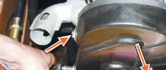
Next, the rear seats, threshold trim, and door seal are dismantled. You need to get to the connector. To do this, bend the clamps and pull off the trim near the shock absorber strut mount. Then disconnect the connector.
Next, the car is raised with a jack, and a block is placed under the bottom for safety. After this, you can unscrew and remove the wheel. The sensor is installed on a bracket. To replace the ABS sensor, you need to spray the bracket with liquid key and wait a little. Then unscrew the mounting bolt. By tapping the element, remove the sensor with a screwdriver.
Then you need to unscrew the fasteners holding the wire brackets. Two bolts on the arch, and one on the shock absorber strut. The wire should be pulled out into the interior.
Installation of the new device is carried out in the reverse order. This completes the operation. Sensors on other car models are changed using a similar scheme (replacing the Lancer ABS sensor is no exception).
If replacing the ABS sensor does not produce results
Having considered the available ways to check the ABS, it may seem that it is enough to identify the problematic sensor and replace it. Replacing the wiring may also seem like a solution.
However, in reality it is not so simple. Often, car enthusiasts are faced with the fact that even after replacing the ABS sensor, the system still does not work. By the way, this also happens in cases where the ABS was working normally, but after replacing the hub or wheel bearings the ABS light comes on.
In this case, computer diagnostics show that there is no signal from the ABS sensor. Next, the sensor is replaced, but the ABS system still does not work. Even if you remove the error using a scanner, after a few meters or after 1-2 braking the error lights up again.
So, the reason in this case is not the sensor at all. Often the culprit is the way the signal is generated from the wheel rotation sensor. More precisely, in the case when the inducing element is the comb ring on the hub (ABS ring). The end part of the sensor itself is located near the comb, which is made of soft magnetic material.
The gap between them is minimal, only from 0.2 to 0.8 millimeters. If dirt or stones adhere to this area, this will lead to a violation of the gap, displacement of the sensor, and destruction of the tip. Naturally, the signal will become weak. Also, the comb itself may become clogged, which causes failures.
Given this feature, before installing a new sensor, you must first check the gap and clean the comb with a solvent. When finished, check the gap size with a feeler gauge. It is not allowed to increase the gap by more than 1 mm. It is also important to inspect the elements for possible damage.
If you are not exactly sure, you can compare the parts with the same devices on another wheel. If damage to the wheel comb is detected, the element needs to be replaced.
Let us also add that the inducing element on some cars can be implemented in the form of a rubber ring or magnetic tape. There are magnetic plates inside the ring. It happens that during in-line repairs this ring is simply not installed. Naturally, the ABS system will not work without them.
As for the tape, it is easy to damage. This means that you need to work carefully, since if the belt is damaged, the ABS sensor will not work properly. It is also important to ensure that when replacing the wheel bearing, an element with an inducing ring is installed in the case where exactly such a design is provided on the car.
How to fix problems
After checking with instruments and identifying the faulty unit, you can begin repairs. Some owners repair the sensors by replacing the wiring harness or rewinding the coil.
Sensor failure
A faulty passive type sensor can be repaired yourself:
- Remove the sensor from the hub. The fastening bolt often becomes sour, so you should unscrew it carefully. For removal it is allowed to use WD40 type fluid.
- Remove the protective coil housing. Removal is done with a file. The cut should be done extremely carefully so as not to damage the housing and winding.
- Remove the protective film from the winding by prying it off with a sharp knife.
- Carefully unwind the wire from the spool. During the removal process, the version of a conductor break is confirmed. As a result, you will be left with an empty ferrite core, resembling a spool of thread in shape.
- Wind a new winding. Copper wire from the coils of common relays of the RES-8 type can be used as a conductor. Winding can be done using a drill with smooth speed control. Be careful as breaking the wire will return you to the start. It is recommended to wind the conductor to the top level of the coil.
- Check resistance. Most coils have a value in the range of 0.9-1.2 kOhm. To clarify, it is recommended to measure the parameter on a known-good sensor located on the opposite side of the axis. The resistance is adjusted by unwinding the excess wire. If the reading is low, you will need to use another wire or re-wind. Secure the wire from unraveling with tape or other adhesive tape.
- Solder the wires to the coil terminals that serve as a connection between the winding and the harness. For outputs, it is recommended to use multi-core insulated cable, which has increased strength.
- Install the coil into the old housing. If it received significant damage when disassembling the device, then the coil is filled with epoxy resin. To do this, the part is located in a metal container of a suitable size, for example, a capacitor housing. The air gap between the coil and the glass is carefully filled with resin. When pouring, it is advisable to avoid large air voids. After the resin has completely hardened, the body is removed.
- Reinstall the sensor mount, securing it with epoxy resin. Conduct a visual inspection of the product for cracks and voids in the insulation. Detected defects are filled with resin.
- Place the repaired sensor in its original place and check the functionality of the ABS system. When installing the device, it may be necessary to modify the resulting body, which is done with a file and sandpaper. The field installed sensor should have a gap between the coil and the toothed ring within 0.9-1.1 mm. When reducing the gap, it is recommended to bring it up to standard by installing gaskets.
It is necessary to drive the car for some time, checking the operation of the brakes at different speeds. There are cases when the ABS spontaneously activates at certain wheel speeds - usually just before stopping. Then you will need to search for the gap, adjusting it with shims or sharpening the sensor body.
Another repair option is to install a modified crankshaft position sensor from domestic cars:
- Remove the “original” sensor and modify the body of the “donor” part. Most often, this role is played by the DPKV from the ZMZ-406 engine, which has a resistance within 800 Ohms. When modifying, you should strive to ensure a parallel arrangement of the core with the wound coil and the toothed ring mounted on the axis. The gap between the sensor and the ring should be within 0.2-0.3 mm.
- Test the operation of the device. On some Japanese-made cars, the ABS lamp may turn on periodically. The situation is corrected by changing the connection of the harness contacts.
Both options for repairing the sensor require perseverance and the ability to work with various tools from the owner. If the car user doubts his abilities, it is recommended to purchase a new device or find the product at a car dismantling site.
Questions about selecting and replacing sensors
DSAs are installed on wheels, so during operation they are subject to various negative influences and various breakdowns occur. A malfunction of the DSA is indicated by the corresponding indicator on the dashboard; also, the failure of one or more sensors is manifested by a change in the nature of the brake system operation - unreasonable activation of the ABS or, conversely, lack of response from the ABS during sudden braking, a characteristic crunch during normal vehicle movement, etc. .d. In all these and other situations, the ABS sensor should be replaced.
For replacement, you should choose sensors only of those types and models (or rather, catalog numbers) that were previously installed on the car. In no case is it permissible to replace the type of sensors, for example, installing a device based on a Hall IC instead of an inductive DSA, and vice versa. Different types of sensors generate certain types of signals, and the ECUs designed to work with them have input circuits that are incompatible with other types of sensors. Therefore, installing the wrong DSA will only aggravate the situation.
Removal of the old sensor and installation of a new one must be carried out strictly in accordance with the vehicle repair and maintenance instructions. Typically, to dismantle the DSA it is necessary to unscrew one screw (bolt) and remove the electrical connector. Then you should thoroughly clean the sensor installation site from any dirt, and then install a new device. After installation, the sensor and the entire system, as a rule, do not require calibration or adjustment - everything starts working immediately.
If you make the right choice and correctly replace the DSA, the active safety systems of your car will again reliably perform their functions, helping the driver overcome difficult and dangerous road situations.
Let's sum it up
Taking into account the above information, it becomes clear that a number of possible nuances should be taken into account as part of diagnosing the ABS system. First of all, it is important to understand that even if the scanner indicates a faulty sensor, replacement is the last thing to do.
At the initial stage, you should separately check the wiring, as well as the gaps between the inducing ring and the tip, the condition of the indicated system elements, etc. It is also important to pay attention to the condition of other parts installed next to the ABS sensors.
Finally, we note that the service life of sensors and other structural elements directly depends on the operating conditions. When driving, avoid driving on rough terrain to avoid damaging the wiring to the ABS sensors. It is also undesirable to plunge the wheels into mud or puddles, drive aggressively in sand, etc. It is also recommended to periodically clean the ABS system parts (with a soft brush or cleaner), and check the gap between the sensor and the comb. Finally, we note that during the repair of the chassis and suspension, it is necessary to separately take into account all the subtleties and nuances discussed above. Only this approach allows you to increase the service life and achieve trouble-free operation of ABS on your car.
Sources
- https://avtozam.com/elektronika/sensor/kak-proverit-datchik-abs/
- https://olade.ru/diagnostika-ABS-svoimi-rukami
- https://autolirika.ru/remont/kak-proverit-datchik-abs.html
- https://auto-gl.ru/kak-ustroen-datchik-abs-ustroystvo-i-princip-raboty-sistemy-abs-i-4-samye-chastye-ee-polomki/
- https://MoyLacetti.ru/proverka-diagnosticheskoj-cepi-abs/
- https://voditeliauto.ru/poleznaya-informaciya/to-i-remont/kak-proverit-datchik-abs.html
- https://avto-moto24.ru/407-proverka-osnovnyx-datchikov-avtomobilya.html
- https://FB.ru/article/439882/zamena-datchika-abs-vidyi-tipyi-printsipyi-rabotyi-i-prichinyi-polomki
- https://voditelauto.ru/datchik-abs/
- https://KrutiMotor.ru/proverka-datchika-abs/
- https://www.avtoall.ru/article/32870790/