21.6. Generator
1 – clamping sleeve;
2 – bushing; 3 – buffer sleeve; 4 – protective casing; 5 – screw for fastening the rectifier unit; 6 – rectifier block; 7 – rectifier block valve; 8 – capacitor; 9 – rear bearing of the rotor shaft; 10 – slip rings; 11 – rotor shaft; 12 – brush connected to terminal “B” of the voltage regulator; 13 – pin “30” for connecting consumers; 14 – brush connected to terminal “Ш” of the voltage regulator; 15 – terminal “B” of the voltage regulator; 16 – voltage regulator; 17 – output “61” of the generator; 18 – stud securing the generator to the tension bar; 19 – impeller; 20 – pulley; 21 – bearing mounting plates; 22 – thrust ring; 23 – front rotor shaft bearing; 24 – rotor winding; 25 – rotor pole piece; 26 – stator winding; 27 – stator; 28 – front cover (drive side).
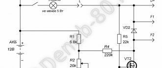
Generator connection diagram 371.3701
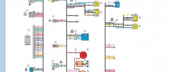
1 – battery; 2 – generator; 3 – instrument cluster; 4 – resistor 51 Ohm, 5 W; 5 – diode;
6 – battery charge indicator lamp; 7 – fuse block; 8 – ignition relay; 9 – ignition switch.
1 – casing; 2 – output “B” for connecting consumers; 3 – capacitor; 4 – common terminal of additional diodes (connected to terminal “D” of the voltage regulator); 5 – holder of positive diodes of the rectifier unit; 6 – holder of negative diodes of the rectifier unit; 7 – positive diode; 8 – negative diode; 9 – voltage regulator; 10 – back cover; 11 – tightening screw; 12 – front cover; 13 – stator winding; 14 – thrust ring; 15 – front rotor shaft bearing; 16 – pulley;
17 – nut; 18 – rotor shaft; 19 – conical washer; 20 – washer; 21 – rotor pole pieces; 22 – stator core; 23 – bushing; 24 – rotor winding; 25 – rear bearing of the rotor shaft; 26 – bearing sleeve; 27 – slip rings; 28 – brush holder; 29 – stator winding terminals; 30 – additional diode; 31 – pin “D” (common pin of additional diodes).
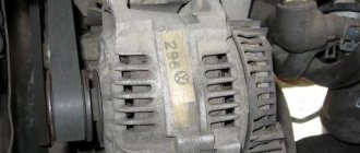
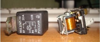
A generator of type 371.3701 is installed on the VAZ-21213 engine, and type 9412.3701 is installed on the VAZ-21214 engine. These generators are structurally similar and are synchronous AC electrical machines with electromagnetic excitation, with a built-in rectifier based on silicon diodes and an electronic voltage regulator. The generator rotor is driven by a V-belt from the engine crankshaft pulley.
Technical characteristics of generator 371.3701
Maximum output current (at 13 V and 6000 min -1 ), A
Technical characteristics of the generator 9412.3701
Maximum output current (at 13 V and 6000 min -1 ), A
The stator and generator covers are secured with four bolts. The rotor shaft rotates in bearings installed in the covers. The lubricant placed in the bearings at the factory is designed to last the entire service life of the generator. The rear bearing of the generator 9412.3701 is pressed onto the rotor shaft and is pressed by the rear cover through a plastic sleeve, the front bearing is pressed and rolled into the front cover and can only be replaced together with it. Its inner race, together with the thrust ring and washer, is clamped by a nut between the pulley and the step on the rotor shaft. The front bearing of the generator 371.3701 is secured with four screws between the inner and outer plates and can be replaced separately from the front cover. The rear part of the generator 9412.3701 is closed with a plastic casing with latches. On the back cover of the generator 371.3701 there is a casing with a rubber air intake, which allows you to take air for cooling the generator from the upper part of the engine compartment, which reduces the likelihood of water getting into the generator when driving through deep puddles and fords. On the 21214 engine, this danger is less, since instead of a mechanical fan of the cooling system (which inevitably splashes water), electric fans are installed there, and they are located in front of the radiator.
The generator stator contains a three-phase winding made in a star configuration (the terminals of the phase windings have a common point). The second ends of the phase windings are connected to a rectifier bridge consisting of six silicon diodes (valves) - three “positive” and three “negative”. The valves are pressed into two horseshoe-shaped aluminum holder plates in accordance with the polarity (positive and negative - on different plates); one of the plates also contains three additional diodes, through which the excitation winding of the generator is powered after starting the engine. The plates are combined into a rectifier unit mounted on the rear cover of the generator (under the plastic casing of the generator 9412.3701).
The excitation winding is located on the generator rotor, its leads are soldered to two copper slip rings on the rotor shaft. Power is supplied to the field winding through two carbon brushes. Alternator slip rings 9412.3701 have a reduced diameter - this reduces the peripheral rotation speed and reduces brush wear. The brush holder is structurally combined with the voltage regulator and is mounted on the back cover of the generator. The voltage regulator is non-separable; if it fails, it is replaced.
Until 1996, for the 371.3701 generator, the brush holder and voltage regulator were separate units (the control voltage from terminal “30” of the generator was supplied to terminal “B” of the voltage regulator). Now voltage is supplied only to terminal “B” (terminal “B” is missing). According to their characteristics, the new and old voltage regulators are the same and, when assembled with a brush holder, are interchangeable.
To protect the on-board network from voltage surges during operation of the ignition system and reduce interference with radio reception, a capacitor with a capacity of 2.2 µF -20% is connected between the terminals of the “positive” and “negative” valves (between the “ ” and the “ground” of the generator), located on the rectifier block generator 9412.3701 and generator rear cover 371.3701.
When the ignition is turned on, voltage is supplied to the excitation winding of the generator (terminal “D” of generator 9412.3701 and “B” of generator 371.3701) through a control lamp in the instrument cluster (the lamp is lit) and resistors connected in parallel to it. After starting the engine, the excitation winding is powered by additional diodes of the rectifier unit (the control lamp goes out). If the lamp lights up after starting the engine, this indicates a malfunction of the generator or its circuits.
The “minus” of the battery should always be connected to the “ground” of the car, and the “plus” to terminal “B” of the generator 9412.3701 (terminal “30” - generator 371.3701). Switching back on will lead to breakdown of the generator valves.
It is not recommended to disconnect the battery when the generator is running (especially on engines equipped with an injection system). The resulting voltage surges in the on-board network can damage the electronic components of the circuit.
Do-it-yourself generator replacement | Repair of Niva VAZ 2121
For most generator repair work on a Niva VAZ 2121 car, it is necessary to remove this part from the car and carry out all work in more convenient conditions. If this spare part needs to be replaced, then below are specific instructions on how to do all this as quickly as possible and without making excessive efforts.
Necessary tool for removing and installing a generator on Niva
- 10mm wrench and ratchet with head
- 19 open-end wrench and head with ratchet handle
- Small extension cord
- Hammer
Progress of replacement work
- The first step is to remove the engine protection, which is attached to several bolts in order to get to the generator mounting bolt from underneath. Spray with WD-40 lubricant if problems arise and unscrew the nut:
- Then, using a hammer with minimal force, so as not to damage the threads of the bolt, we knock it out, tapping it a little so that it comes out in the opposite direction.
- And immediately after this, we remove this long bolt with our hands, slightly turning the generator itself from side to side to make it easier to remove the rod:
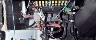
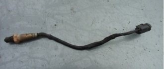
- Next, you need to disconnect all power wires from the Niva generator housing. First, you can disconnect the plug with the wires that come from it:
- And the wires that are tightened with a nut, which will need to be unscrewed with a 10mm wrench, and after the connection is loosened, it is better to use a ratchet handle to carry out this procedure faster:
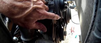
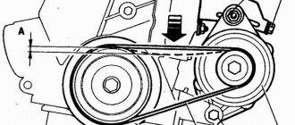
- Next, you can begin to unscrew the upper mount with the belt tensioner, for which you will need a socket with a small extension. Everything is clearly shown in the photo below:
- And then you can free yourself from the belt and remove the part by simply lowering it down through the hole, which became free due to the removal of the engine protection.
Replacing a new generator and installing it is done in the reverse order of removal and will not take you more than an hour of time if you have the necessary tools.
After everything has been put in place, it will be necessary to adjust the position using the tensioner at the top, unscrewing its nut and tightening or loosening the belt until the battery charging returns to normal and at the same time there is no overtightening to avoid the building a bearing.
Design features and testing of generators of the Niva VAZ-21213, VAZ-21214
A generator of type 371.3701 is installed on the VAZ-21213 engine, and type 9412.3701 is installed on the VAZ-21214 engine. These generators are structurally similar and are synchronous AC electrical machines with electromagnetic excitation, with a built-in rectifier based on silicon diodes and an electronic voltage regulator.
Technical characteristics of generators 371.3701 and 9412.3701
Maximum output current (at 13 V and 6000 min -1 ), A
Direction of rotation (drive side)
The generator rotor is driven by a V-belt from the engine crankshaft pulley.
The stator and generator covers are secured with four bolts.
The rotor shaft rotates in bearings installed in the covers.
The lubricant placed in the bearings at the factory is designed to last the entire service life of the generator.
The rear bearing of the generator 9412.3701 is pressed onto the rotor shaft and is pressed by the rear cover through a plastic sleeve, the front bearing is pressed and rolled into the front cover and can only be replaced together with it.
Its inner race, together with the thrust ring and washer, is clamped by a nut between the pulley and the step on the rotor shaft.
The front bearing of the generator 371.3701 is secured with four screws between the inner and outer plates and can be replaced separately from the front cover.
The rear part of the generator 9412.3701 is closed with a plastic casing with latches.
On the back cover of the generator 371.3701 there is a casing with a rubber air intake, which allows you to take air for cooling the generator from the upper part of the engine compartment, which reduces the likelihood of water getting into the generator when driving through deep puddles and fords.
On the 21214 engine, this danger is less, since instead of a mechanical fan of the cooling system (which inevitably sprays water), electric fans are installed there, and they are located in front of the radiator.
The generator stator contains a three-phase winding made in a star configuration (the terminals of the phase windings have a common point).
The second ends of the phase windings are connected to a rectifier bridge consisting of six silicon diodes (valves) - three “positive” and three “negative”.
The valves are pressed into two horseshoe-shaped aluminum holder plates in accordance with the polarity (positive and negative - on different plates); one of the plates also contains three additional diodes, through which the excitation winding of the generator is powered after starting the engine. The plates are combined into a rectifier unit mounted on the rear cover of the generator (under the plastic casing of the generator 9412.3701).
The excitation winding is located on the generator rotor, its leads are soldered to two copper slip rings on the rotor shaft.
Power is supplied to the field winding through two carbon brushes.
Alternator slip rings 9412.3701 have a reduced diameter - this reduces the peripheral rotation speed and reduces brush wear.
The brush holder is structurally combined with the voltage regulator and is mounted on the back cover of the generator.
The voltage regulator is non-separable; if it fails, it is replaced.
Until 1996, for the 371.3701 generator, the brush holder and voltage regulator were separate units (the control voltage from terminal “30” of the generator was supplied to terminal “B” of the voltage regulator). Now voltage is supplied only to terminal “B” (terminal “B” is missing). According to their characteristics, the new and old voltage regulators are the same and, when assembled with a brush holder, are interchangeable.
To protect the on-board network from voltage surges during operation of the ignition system and reduce interference with radio reception, a capacitor with a capacity of 2.2 µF + -20% is connected between the terminals of the “positive” and “negative” valves (between the “+” and “ground” of the generator), located on generator rectifier block 9412.3701 and generator rear cover 371.3701.
When the ignition is turned on, voltage is supplied to the excitation winding of the generator (terminal “D” of generator 9412.3701 and “B” of generator 371.3701) through a control lamp in the instrument cluster (the lamp is lit) and resistors connected in parallel to it.
After starting the engine, the excitation winding is powered by additional diodes of the rectifier unit (the control lamp goes out). If the lamp lights up after starting the engine, this indicates a malfunction of the generator or its circuits.
The “minus” of the battery should always be connected to the “ground” of the car, and the “plus” to the “B+” terminal of the generator 9412.3701 (terminal “30” of the generator 371.3701).
Switching back on will lead to breakdown of the generator valves. It is not recommended to disconnect the battery when the generator is running (especially on engines equipped with an injection system).
The resulting voltage surges in the on-board network can damage the electronic components of the circuit.
The generator valves (and other devices in the vehicle’s on-board network when the generator is connected) should be checked at a voltage no higher than 14 V; a higher voltage (for example, when checking with a megger) can cause damage to the valves.
If it is necessary to check the insulation of windings with high voltage, the generator should be removed, and the winding terminals should be disconnected from the rectifier unit and voltage regulator.
Replacing a generator on Niva
Hello dear homemade people.
If your fuel-injected Niva’s generator has broken down and urgently needs to be replaced, then you don’t have to go to the service center for this, since this is not a difficult task and is quite within the capabilities of a normal man.
You can replace the generator without a pit and without a lift. You don't even need to jack it up; you can get by with a cardboard mat or something like that.
Before starting work, disconnect the battery terminals!
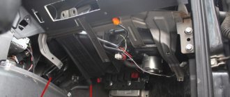
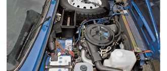
The generator is located on the right side of the engine at the bottom but can also be seen from above, immediately below the pump.
But you can only replace it from below. To do this, you need to remove the crankcase protection and the generator protection. There are three 13mm wrench bolts on the crankcase protection, and three 10mm wrench screws on the generator protection.
It’s better to unscrew with heads, or at least with socket heads, and just in case, prepare a VDeshka, since the place is quite dirty and wet and an open-end wrench is usually useless there.
After removing the protection, the generator is clearly visible and fully accessible.
The generator is secured with two bolts with self-locking nuts 13mm, one on the support leg and one on the tension leg.
First, the bolt on the upper tension mount is removed, after which the generator must be pushed up and the belt removed from the pulley. There is only one belt - for the generator and for the pump.
Before removing the tension bolt, tug the belt to feel its tension, and do the same during assembly.
Next, the generator is pulled down and the electrical wires are disconnected. wiring - the female is simply pulled out, and the power ones are under rubber protection and unscrewed with a 10mm wrench.
Then the nut on the support leg, located on the rear side, is unscrewed, after which the bolt is pulled forward and the generator is removed.
Installing a new generator is done in the reverse order. The only additional thing you have to do is tighten the belt. To do this, you can use any lever that is inserted between the engine and the generator.
In the next article we will repair an old generator.
Generator VAZ 21214. Technical features and characteristics
The VAZ 21214 (9412.3701) generator is a synchronous AC electric machine with electromagnetic excitation, with an electronic voltage regulator and a built-in rectifier.
Below are the technical characteristics of the generator 9412.3701
- Direction of rotation – right
- Voltage, V 13.2 - 14.7
- Maximum output current, A 80
The generator covers are fixed to the stator using 4 bolts. They contain bearings that operate in lubricant, on which the rotor shaft rotates. The lubricant itself is contained in them for the entire service life. The front bearing of the generator 9412.3701 is rolled and pressed into the front cover, so replacement is only possible as a kit. The inner race of this bearing is clamped with a nut between the step and the pulley on the rotor shaft, complete with a washer and thrust ring. The rear bearing is not only pressed onto the rotor shaft, but is also pressed against it by means of a plastic bushing installed in the rear cover. The back part itself is closed with a special casing made of plastic and secured with latches.
The generator stator has a three-phase winding, and its terminals have a common point (the so-called “star” circuit). The second ends of the windings are fixed to a bridge (rectifier), the design of which includes 6 silicon valves (diodes) - 3 “negative” and “positive” each. The valves themselves are pressed into special plates made of aluminum and having a horseshoe shape. This was done taking into account polarity - “negative” and “positive” go to different plates. They are connected into a special unit (rectifier), which is fixed on the rear cover of the generator, located under a plastic casing. One of these plates has 3 additional diodes, through which power is supplied to the generator excitation winding (after starting the power unit). The excitation winding itself is located on the generator rotor, and the leads coming from it are soldered to 2 slip rings made of copper and mounted on the rotor shaft. Power is supplied to them through 2 brushes (carbon).
How to remove a Niva Chevrolet generator video
no charging Niva Chevrolet.
generator repair, alternator belt replacement in the field☝
Niva Chevrolet: Generator is the most common problem
How to replace the alternator belt on a Chevrolet Niva with air conditioning?
Generator bearings. How to replace.
Chevrolet Generator Repair
Loose terminal of the Niva Chevrolet generator
replacing the alternator belt on a Chevrolet Niva
What happens to the VAZ 21214 m generator when crossing a ford or water obstacle
Diode bridge and how to replace it without errors.
Generator - device, characteristics, operation check
371.3701 is installed on the VAZ-21213 carburetor engine 9412.3701 is installed on the VAZ-21214 injection engine . These generators are structurally similar and are synchronous AC electrical machines with electromagnetic excitation, with a built-in rectifier based on silicon diodes and an electronic voltage regulator. The generator rotor is driven by a V-belt from the engine crankshaft pulley.
Generator 371.3701
1 – clamping sleeve; 2 – bushing; 3 – buffer sleeve; 4 – protective casing; 5 – screw for fastening the rectifier unit; 6 – rectifier block; 7 – rectifier block valve; 8 – capacitor; 9 – rear bearing of the rotor shaft; 10 – slip rings; 11 – rotor shaft; 12 – brush connected to terminal “B” of the voltage regulator; 13 – pin “30” for connecting consumers; 14 – brush connected to terminal “Ш” of the voltage regulator;
15 – terminal “B” of the voltage regulator; 16 – voltage regulator; 17 – output “61” of the generator; 18 – stud securing the generator to the tension bar; 19 – impeller; 20 – pulley; 21 – bearing mounting plates; 22 – thrust ring; 23 – front rotor shaft bearing; 24 – rotor winding; 25 – rotor pole piece; 26 – stator winding; 27 – stator; 28 – front cover (drive side).
Generator connection diagram 371.3701
1 – Battery; 2 – generator; 3 – instrument cluster; 4 – resistor 51 Ohm, 5 W; 5 – diode;
6 – battery charge indicator lamp; 7 – fuse block; 8 – ignition relay; 9 – ignition switch.
Generator 9412.3701
1 – casing; 2 – output “B” for connecting consumers; 3 – capacitor; 4 – common terminal of additional diodes (connected to terminal “D” of the voltage regulator); 5 – holder of positive diodes of the rectifier unit; 6 – holder of negative diodes of the rectifier unit; 7 – positive diode; 8 – negative diode; 9 – voltage regulator; 10 – back cover; 11 – tightening screw; 12 – front cover; 13 – stator winding; 14 – thrust ring; 15 – front rotor shaft bearing; 16 – pulley;
17 – nut; 18 – rotor shaft; 19 – conical washer; 20 – washer; 21 – rotor pole pieces; 22 – stator core; 23 – bushing; 24 – rotor winding; 25 – rear bearing of the rotor shaft; 26 – bearing sleeve; 27 – slip rings; 28 – brush holder; 29 – stator winding terminals; 30 – additional diode; 31 – pin “D” (common pin of additional diodes).
Technical characteristics of generator 371.3701
Maximum output current (at 13 V and 6000 min -1 ), A
Technical characteristics of the generator 9412.3701
Maximum output current (at 13 V and 6000 min -1 ), A
The stator and generator covers are secured with four bolts. The rotor shaft rotates in bearings installed in the covers. The lubricant placed in the bearings at the factory is designed to last the entire service life of the generator. The rear bearing of the generator 9412.3701 is pressed onto the rotor shaft and is pressed by the rear cover through a plastic sleeve, the front bearing is pressed and rolled into the front cover and can only be replaced together with it. Its inner race, together with the thrust ring and washer, is clamped by a nut between the pulley and the step on the rotor shaft. The front bearing of the generator 371.3701 is secured with four screws between the inner and outer plates and can be replaced separately from the front cover. The rear part of the generator 9412.3701 is closed with a plastic casing with latches. On the back cover of the generator 371.3701 there is a casing with a rubber air intake, which allows you to take air for cooling the generator from the upper part of the engine compartment, which reduces the likelihood of water getting into the generator when driving through deep puddles and fords. On the 21214 engine, this danger is less, since instead of a mechanical fan of the cooling system (which inevitably splashes water), electric fans are installed there, and they are located in front of the radiator.
The generator stator contains a three-phase winding made in a star configuration (the terminals of the phase windings have a common point). The second ends of the phase windings are connected to a rectifier bridge consisting of six silicon diodes (valves) - three “positive” and three “negative”. The valves are pressed into two horseshoe-shaped aluminum holder plates in accordance with the polarity (positive and negative - on different plates); one of the plates also contains three additional diodes, through which the excitation winding of the generator is powered after starting the engine. The plates are combined into a rectifier unit mounted on the rear cover of the generator (under the plastic casing of the generator 9412.3701).