Design and operation of a simple carburetor
The design and operation of a simple carburetor. To properly operate a carburetor, it is necessary to study, first of all, its design features and understand the principles of operation of the systems in various modes, know possible malfunctions and misadjustments, the causes of their occurrence, as well as methods for detecting and eliminating them.
Rice. 2. Schematic diagram of a simple carburetor: 1 - float chamber; 2 – lever; 3 – float; 4 – needle; 5 - fuel valve; 6 - fuel channel; 7 - sprayer; 8 — main air channel; 9 – diffuser; 10 — throttle valve; 11 - fuel jet.
In the float chamber, due to the float with a needle and the fuel valve, a constant level of fuel h coming from the gasoline tank is maintained.
The main air passage supplies air to the carburetor. In the middle part it narrows, forming a diffuser designed to increase air flow speed and provide improved conditions for fuel evaporation and mixture formation.
Throttle valve 10 is designed to change the amount of combustible mixture entering the engine cylinders in accordance with the required power.
The outflow of fuel from the nozzle is accompanied by the expenditure of energy to lift it to the atomizer 7. The disintegration of the fuel jet begins when the difference between the speeds of the fuel and the air flow is 4-6 m/s. In a modern carburetor, the droplet size is 20-120 microns.
The optimal droplet size is 50 microns. In this case, the fineness of fuel atomization (crushing) decreases with increasing fuel temperature due to a decrease in the surface tension coefficient and an increase in the difference between the relative speed of the fuel and the air flow. The fuel flow rate is 25 times less than the air flow rate.
The carburetor operates in accordance with the ejection (pulverization) principle. Under the influence of vacuum, which represents the difference between the pressure in the float chamber and in the carburetor diffuser, fuel from the float chamber through the fuel nozzle and atomizer enters the diffuser, and then into the main air channel.
In modern carburetors, fuel flow begins when a vacuum reaches 100 Pa (10 mm water column). At lower values, only clean air flows through the carburetor. The decrease in pressure in the atomizer zone is due to an increase in the air flow speed in the diffuser and local resistance.
When the engine is not running, the pressure in the float chamber and in the sprayer zone in the diffuser is the same. When the engine starts, the vacuum generated in the cylinder during the suction stroke is transmitted through the intake manifold and the main air jet to the sprayer area. As a result, due to the resulting pressure difference in the float chamber and diffuser, fuel flows from the float chamber to the atomizer and flows out of it into the main air channel, mixes with air and enters the cylinders.
Increasing the speed of air flow as it passes through the diffuser leads to a further decrease in pressure in the nozzle area. It is possible to reduce the cross-section of the diffuser only to a certain limit, since in the future this causes increased resistance to the passage of air, which is accompanied by a decrease in engine power due to a decrease in the cylinder filling ratio.
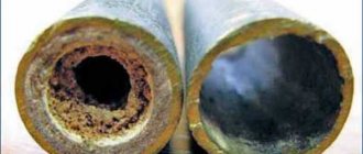
The formation of a combustible mixture in the mixing chamber of the carburetor does not occur in full. Some of the fuel in the form of droplets does not have time to evaporate and mix with air. Unevaporated fuel droplets move in the air flow and settle on the walls of the mixing chamber and inlet pipe. Fuel deposited on the walls forms a film that moves at low speed.
To evaporate the fuel film, the intake manifold is heated when the engine is running. Most often, liquid heating (from the engine cooling system) or heating with exhaust gas heat is used. Thus, we can assume that the formation of a combustible mixture ends at the end of the engine intake pipe.
Depending on the direction of air flow in the mixture-forming device, carburetors are divided into several types. The most widely used are carburetors in which the combustible mixture moves from top to bottom (Fig. 2). Such carburetors are called falling-flow carburetors . They provide high power and economic performance and a convenient location on the engine for maintenance. Carburetors with upward movement of the fuel mixture are called updraft carburetors . They are obsolete designs and therefore will not be considered by us.
For modern multi-cylinder engines, two-chamber carburetors with parallel and sequential opening of throttle valves . “Two-chamber” carburetors are named after the number of mixing devices, or mixing chambers, they contain. A two-chamber carburetor (Fig. 3) with parallel opening of the throttle valves has two mixing chambers 2, one float chamber 1 and two throttle valves 3 mounted on the same axis. When the axis is turned, the throttle valves will open the cross-section of the exhaust pipes 4 of the carburetor synchronously, ensuring parallel action of the mixing chambers. Each mixing chamber of the carburetor is connected to a group of cylinders by a separate pipeline and supplies them with a combustible mixture.
A two-chamber carburetor with sequential opening of the throttle valves has approximately the same device. The only difference is in the drive of the throttle valves and the design of the outlet pipe, which is common to both mixing chambers. When this carburetor operates, the throttle valve of one chamber (the main one) opens first. As soon as the first valve opens 70-80% of its full opening, the throttle valve of the second chamber (additional) begins to open. At the same time, an additional mixing chamber comes into operation, ensuring that a large amount of combustible mixture enters the cylinders.
Rice. 3. Two-chamber carburetor with parallel opening of the throttle valves: 1— float chamber; 2 - mixing chambers; 3 — throttle valves; 4 — carburetor exhaust pipes.
The number of chambers in carburetors is not limited to two, but is determined by the number and location of the engine cylinders. So, the BMW 740 engine has a carburetor with 4 chambers, and it works like two two-chamber carburetors with sequential opening of the throttle valves. The use of multi-chamber (two-chamber) carburetors makes it possible to improve the filling of the engine cylinders with a combustible mixture, since the pressure loss of the mixture in the intake pipes is reduced. This is explained by the fact that the mixture constantly moves in one direction. Such carburetors give especially good results in V-shaped engines , where each carburetor chamber supplies one row of cylinders with a combustible mixture.
The use of multi-chamber carburetors increases engine power, reduces fuel consumption and exhaust gas toxicity. This advantage of multi-chamber carburetors is most fully manifested in carburetors with sequential opening of the throttle valves.
Carburetors - Solex, Ozone. A manual for the repair and maintenance of automobile carburetors of the brand Ozone and Solex. Each manual outlines the operating principles of the main carburetor systems and describes the design of carburetors of the Solex and Ozone families. Possible malfunctions, their causes and solutions are discussed in detail. The processes of adjustment, repair and modification of carburetors are illustrated and provided with detailed comments. Carburetor repair instructions are intended for drivers who want to independently service and repair cars with engines equipped with Solex and Ozone carburetors .
Similar articles:
- Float chamber ventilation device
- Basic structure of the power system
- Carburetor idle system K-156
- Idle system of carburetor K-151
- Idle system of the DAAZ-21081 carburetor
- Carburetor idle system VAZ-2101, -2103 and -2106
Carburetor idle system 2108, 21081, 21083 Solex
Purpose of the Solex carburetor idle system
The idle system of the carburetor 2108, 21081, 21083 "Solex" and its modifications is designed to ensure that the car engine operates without load with minimal crankshaft speed (750-800 rpm).
Design of the carburetor idle system 2108, 21081, 21083 Solex
Diagram of the idle system of the Solex carburetor 2108, 21081, 21083
Additionally: “Diagram of the idle system and transition systems of the carburetor 2108, 21081, 21083 Solex.”
Visible elements of the Solex carburetor idle system (2108, 21081, 21083)
Visible elements of the CXX carburetor 2108, 21081, 21083 Solex
Visible elements of the Solex carburetor idle system with the top part (“cover”) removed.
Visible elements of the CXX carburetor 2108, 21081, 21083 Solex with the cover removed
Solenoid valve (EMV) of the Solex carburetor (2108, 21081, 21083) with a shut-off needle and a fuel jet for the idle system.
Electromagnetic valve EPHH of a Solex carburetor with fuel jet CXX
Operating principle of the idle system
The outlet of the idle air system (IAC) is located below the edge of the throttle valve of the first chamber in its closed position (See photo at the beginning of the article). Under the influence of vacuum entering this hole, fuel from the float chamber is drawn into the emulsion channel of the idle system.
Air also enters there through the air nozzle and the air channel of the system. In the emulsion channel, fuel and air are mixed to form an emulsion, which enters under the throttle valve and exits the idle system opening.
Next, the emerging emulsion is mixed with some air coming from the gap between the edge of the throttle valve and the wall of the first chamber of the carburetor. A fuel mixture is formed, which enters the engine cylinders and ensures its operation at idle speed.
The quality of the fuel mixture is regulated by a screw installed in the emulsion outlet hole. By turning it, we reduce the clearance of the hole and the volume of fuel entering the fuel mixture decreases. It should be noted that the composition of the fuel mixture prepared by SXX is enriched, which allows the engine to operate stably at minimum speed.
The amount of fuel mixture is regulated by a screw that slightly opens the throttle valve of the first chamber. By turning the screw, we open the damper to a larger angle, thereby ensuring the flow of additional air under it and, accordingly, the volume of the fuel mixture entering the engine cylinders increases (idle speed increases).
Screws for adjusting the quantity and quality of the fuel mixture at idle speed of an engine with a Solex carburetor 2108, 21081, 21083 (the choke control lever has been removed for clarity)
Malfunctions of the idle system of the Solex carburetor 2108, 21081, 21083
Malfunctions of the Solex 2108 CXX include: clogged channels and jets, clogged outlet, incorrect adjustment of the fuel supply with screws, malfunction of the solenoid valve or EPH system, incorrect position of the throttle and (or) air dampers. Details about all the problems of the system: “The idle system of the Solex carburetor 2108, 21081, 21083 does not work.”
As a result, the engine “troubles”, stalls and refuses to start normally.
Notes and additions
— In some cases, it makes sense to modify the carburetor idle system. See “Modification of the idle system of Solex and Ozone carburetors.”
More articles on Solex carburetors 2108, 21081, 21083
— Solex quality screw 21083, device, applicability
— Acceleration pump carburetor 2108, 21081, 21083 Solex
— Econostat carburetor 2108, 21081, 21083 Solex
— Schemes of carburetors 2108, 21081, 21083 Solex
— Disassembling carburetor 2108, 21081, 21083 Solex
— Cleaning the idle system of the carburetor 2108, 21081, 21083 Solex
How does a carburetor work?
The carburetor design includes several additional systems that help the internal combustion engine operate correctly.
- The main additional system is the carburetor trigger; without it, it simply will not work, which means there will be no fuel for combustion.
- The second system is the idle system. This system ensures that the internal combustion engine operates while the car is stationary.
- Well, the last main system here is the accelerator pump and the system for dosing the fuel composition.
- There is another system that sucks air into the system using a special piston and an air duct opening. The carburetor especially needs air to mix it with fuel. But before entering the carburetor, air and fuel pass through a special filter. This is necessary in order not to damage or clog all the holes.
The filtration system is one of the main parts with which the carburetor engine power system is equipped. This system is very important for protecting the internal combustion engine from clogging, because the air contains dust and other small particles. There are many types of filters, but they have the same principle and purpose. The whole principle is based on the fact that air with various particles passes through meshes, holes and other obstacles and is cleaned, leaving all the debris on the obstacles. Using the same principle, gasoline undergoes filtration before it ends up in the tank. There are many different diagrams on the Internet that show the principles of operation of systems.
Mixing liquid with air is the basic principle of operation of a carburetor. The name of the carburetor comes from “carburation”, in French this means mixing air and liquid. In this case, gasoline and air are mixed.
A carburetor engine, like any other, is equipped with a pump that accelerates the supply of fuel, a fuel mixture metering device and an idle system. The carburetor works in such a way that before entering the cylinder, the air passes through the mixing chamber, where it takes fuel particles with it, after which it is sent into the cylinder, because the piston moves down and opens the intake valve.
Basic structure of the power system
The power supply system (Fig. 1) is designed to store fuel reserves in a vehicle, purify fuel and air, form a combustible mixture, supply it to the engine cylinders and remove exhaust gases from them. The power system of a carburetor engine must ensure high reliability of engine operation in various operating conditions of the vehicle, specified fuel consumption, minimal pollution of the surrounding air by exhaust gases, fire safety, ease of diagnosis and maintenance.
Rice. 1. Schematic diagram of the carburetor engine power supply system:
1 — fuel level indicator; 2 — fuel level indicator sensor; 3 — fuel tank filler cap; 4 — fuel tank; 5 — muffler; 6 - settling filter; 7 — exhaust pipe; 8 — engine; 9 — fuel pump; 10 — fine fuel filter; 11 - exhaust pipeline; 12 — inlet pipeline; 13 — air filter; 14 - carburetor. When the engine is running, fuel (gasoline) is pumped from the tank and, passing through pipelines and fuel filters, is supplied to the carburetor, where it is atomized and mixed in a certain proportion with air, which enters the carburetor through the air filter. This mixture of fuel and air prepared in the carburetor is called a combustible mixture , which is supplied through the intake manifold to each engine cylinder during the intake stroke. In the cylinder, the combustible mixture is mixed with combustion products remaining after the previous stroke and forms a working mixture . Further, during the compression stroke, the working mixture is compressed. At the end of the compression stroke, it is ignited by the spark discharge of the spark plug and burns, increasing in volume and doing useful work to move the piston. The exhaust gases generated during the power stroke are discharged through the muffler into the atmosphere during the exhaust stroke. There may be some design differences in the power systems of different carburetor engines. Thus, to reduce noise when air is admitted into the carburetor, intake noise mufflers can be installed between the air filter and the carburetor.
Fuel filters for passenger car engines are sometimes combined with a carburetor or fuel pump. A separate version of these filters is usually adopted for engines of trucks and buses. To protect the engine from excessive increases in crankshaft speed, which can occur when the engine is running without load, a speed limiter is provided in the power system. Typically, such limiters are installed on carburetors of truck engines (for example, a ZIL-130 car). The devices of the engine power supply system are connected to each other by metal fuel lines, as well as hoses made of oil- and petrol-resistant rubber or plastic.
Car design for dummies
THE SIMPLE CARBURETOR (Fig. 17) has two interconnected chambers: a float chamber and a mixing chamber. The float chamber is a reservoir, inside of which a hollow float is suspended on an axis. A needle valve is located above the float, blocking the access of fuel from the fuel pump to the chamber. As the chamber is filled with fuel, the float floats up and, when the fuel reaches the required level, closes the valve. If the level drops, the float will immediately drop, the valve will open and fuel will again begin to flow into the float chamber.
So, with the help of a float device, the required fuel level is maintained in the carburetor. It should be 1.5-2 mm below the outlet - the mouth of the sprayer. At this level, fuel does not flow out of the nozzle when the engine is not running, but when less pressure occurs in the mixing chamber than in the float chamber, it begins to flow into the mixing chamber.
A flammable mixture is formed in the mixing chamber. This chamber consists of a housing in which a diffuser, a spray tube with a nozzle and a throttle valve are located. Air enters the mixing chamber from above. The lower part of the chamber is connected to the inlet pipeline, through which the combustible mixture passes into the combustion chamber and fills the cylinder. The highest speed of air movement in the mixing chamber will be in its narrowest place - the diffuser, in the center of which the mouth of the nozzle is located. A jet is a plug with a calibrated (precisely sized) hole that strictly limits the exit of fuel from the float chamber through the nozzle into the mixing chamber.
The throttle is connected through several drive parts to a pedal, with the help of which it opens and closes. By acting on this pedal with the right foot, the driver can change the degree of throttle opening and thereby the amount of combustible mixture entering the cylinders. The number of revolutions of the engine crankshaft and the vehicle speed change accordingly. The simplest carburetor works like this. During the intake stroke, when a vacuum is created in the engine cylinder, and consequently in the mixing chamber of the carburetor, fuel flows out of the nozzle. The strong air flow that arises in the mixing chamber, just as it does in a spray bottle, picks up a stream of fuel, atomizes it and carries it into the cylinder. This creates a flammable mixture. On the way to the cylinder and even in the cylinder itself, fuel particles evaporate and the mixture becomes vaporous. In the cylinder, the combustible mixture, mixing with the remaining exhaust gases, forms the so-called working mixture. However, the simplest carburetor is not able to ensure the engine operates well enough. Depending on the thermal state of the engine (cold or warm) and its operating mode, the composition of the mixture must change: for example, to start and warm up a cold engine, a rich combustible mixture is needed, since part of the fuel settles on the cold walls of the cylinders and is thus not used when burning. Therefore, unless the mixture has excess fuel, it will be difficult to ignite. At average loads, the engine must receive a lean mixture, that is, have some excess air, which ensures the most complete combustion of fuel, thereby reducing its consumption. When the engine requires the most power (at higher loads), the mixture must be richer. At low speeds (idling), the engine also needs a rich mixture, since it enters the cylinders in no greater quantity. In order to prepare a combustible mixture of the most favorable composition depending on the operating conditions of the engine, it is necessary to equip the carburetor with a number of additional devices. A modern carburetor, in addition to the float and mixing chambers with a diffuser and throttle, has: a starting device, an idle system, a main metering system, an accelerator pump, and an economizer.
‹ Formation of a flammable mixture Up Main dosing system of the carburetor ›
How to make an economical carburetor
A car carburetor is a device responsible for supplying fuel, gasoline or diesel, to the engine. And, naturally, many drivers have a completely natural question: how to adjust the carburetor so that the fuel supply is sufficient, but there is no overconsumption.
1
In order to partially reduce the fuel consumption of your car, where fuel is supplied by a carburetor, you need to purchase a carburetor repair kit. In particular, a repair kit in which the jet size is smaller than on the carburetor of your car. The nozzle performs the function of supplying the fuel mixture from the float section to the atomizer. The amount of fuel supplied directly depends on the size and shape of the nozzle, which means that the smaller it is, the less fuel will enter the atomizer.
2
Some auto mechanics believe that the problem with many carburetors is overflow in the second chamber, therefore, to reduce fuel consumption, the fuel supply in the second chamber of the carburetor should be reduced.
3
Remove the carburetor from the car, disassemble it and replace the stock jets with smaller parts. Then assemble and install the carburetor. Tighten the fuel adjustment bolt as tightly as possible, and do the same with the solenoid valve if your carburetor has one. Use the key, don't rely on hand strength. After installing a carburetor with smaller jets, fuel consumption should partially decrease.
4
Another option for reducing fuel consumption is also based on the difference in jet sizes, but you do not need a repair kit. You just need to remove and disassemble the carburetor, and simply swap the jets of the first and second chambers. Also make sure that the float in the float chamber is slightly torn off from the carburetor cover (about 1-3 mm); do not make the level too small, otherwise, instead of saving money, you will get unstable engine operation.
5
Remember that fuel efficiency depends not only on the setting and regulation of the carburetor, but also on your driving style, as well as on the quality of the road, weather and climate conditions, the condition of filters and other vehicle systems, and fuel quality.
There is an opinion that no matter how much you adjust the carburetor, how much fuel the engine is supposed to consume to produce a particular amount of horsepower, that’s how much it will consume. And for uniform fuel consumption, it is not enough just to adjust the carburetor correctly; it is also necessary to monitor the proper condition of other vehicle systems. And then fuel consumption will be at the level declared by the manufacturer, because this figure depends on a combination of many factors.