Lada/VAZ-2110, -2111, -2112 operation, maintenance and repair
VAZ-2110 and its modifications (VAZ-2111 and VAZ-2112) are a five-seater passenger car with a front engine, front-wheel drive and an all-metal welded body with a supporting structure. Body types: VAZ-2110 – sedan, VAZ-2111 – station wagon, VAZ-2112 – hatchback. Cars of the “tenth” family are equipped with four-cylinder, four-stroke, eight- and sixteen-valve gasoline engines with a volume of 1.5 and 1.6 liters and a power (according to GOST 14846–81 net) from 52.0 to 66.7 kW. Power supply systems: carburetor and distributed fuel injection. To comply with modern Euro-2 and Euro-3 exhaust gas toxicity standards, cars with injection engines are equipped with catalytic converters or cat manifolds with oxygen concentration sensors. Cars with carburetor engines do not have neutralizers in their equipment.
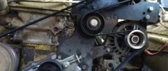
Engine VAZ-2111 Gasoline, four-stroke, four-cylinder, in-line with a transverse arrangement, eight-valve, with an overhead camshaft. The operating order of the cylinders is: 1-3-4-2, counting from the crankshaft pulley. The power supply system is distributed injection. Engine control – controller (Bosch, “January” or GM). Most engines are equipped with an exhaust gas converter. To meet the maximum power requirements (58.3 kW according to DIN), some engines are equipped with a receiver with shortened channels and a camshaft 2110. Some engines are equipped with a phased injection system. In this case, there is a pin for the phase sensor on the camshaft (camshaft index - 2111). The engine, gearbox and clutch form the power unit - a single unit mounted in the engine compartment on three elastic rubber-metal supports. The right support is attached to the engine bracket, and the left and rear ones are attached to the gearbox housing brackets. The right and left supports are similar in design. On the right side of the engine (along the direction of the car) are located: the drives of the camshaft and coolant pump (by a toothed belt) and the generator (by a V-ribbed belt). On the left are: thermostat, coolant temperature sensors, starter (on the clutch housing). Front: spark plugs and high voltage wires, knock sensor, oil dipstick, crankcase ventilation hose, alternator (lower right). Rear: receiver, fuel rail, injectors, intake and exhaust manifolds, oil filter, oil pressure sensor. The cylinder block is cast from cast iron and does not differ from the engine block 21083 and 2110. The cylinders are bored directly into the block. The nominal diameter is 82 mm; during repairs it can be increased by 0.4 or 0.8 mm. The class of the cylinder is marked in Latin letters on the bottom plane of the block in accordance with the diameter of the cylinder in mm: A – 82.00-82.01, B – 82.01-82.02, C – 82.02-82.03, D – 82 .03-82.04, E – 82.04-82.05. The maximum permissible cylinder wear is 0.15 mm per diameter. At the bottom of the cylinder block there are five main bearing supports with removable caps, which are attached to the block with special bolts. The holes for the bearings are machined together with the covers, so the covers are not interchangeable and are marked with marks on the outer surface to distinguish them (see the figure in the section “Disassembling and assembling the engine”). The middle support has slots for thrust half-rings that prevent axial movement of the crankshaft. The steel-aluminum half-ring (white) should face the crankshaft pulley, and the cermet (yellow) should face the flywheel. In this case, the grooves on them should face the surfaces of the crankshaft. Half rings are supplied in nominal and 0.127 mm larger sizes. If the axial clearance (play) of the crankshaft exceeds 0.35 mm, then replace one or both half rings (nominal clearance 0.06-0.26 mm). The main and connecting rod bearing shells are thin-walled steel-aluminum. The upper main bearings (installed in the cylinder block) of the first, second, fourth and fifth bearings have a groove on the inner surface. The lower main bearings and the upper bearing of the third support are without a groove, just like the connecting rod bearings. Repair liners are produced for crankshaft journals, reduced by 0.25, 0.50, 0.75 and 1.00 mm. The crankshaft is made of high-strength cast iron, with five main and four connecting rod journals. The shaft is equipped with eight counterweights cast integrally with it. To supply oil from the main journals to the connecting rods, there are channels whose outlet holes are closed with pressed-in plugs. At the same time, the channels also participate in oil purification: under the influence of centrifugal force, solid particles and resins passing through the filter are thrown back to the plugs. Therefore, during any dismantling of the shaft, it is advisable (and when balancing the shaft, it is mandatory) to clean the channels from accumulated deposits. The plugs cannot be reused - they are replaced with new ones. At the front end (toe) of the crankshaft, a toothed camshaft drive pulley is mounted on a segment key. The generator drive pulley is attached to it on a pin, which simultaneously serves as a damper for torsional vibrations of the crankshaft (due to the elastic element between the central and outer parts of the pulley). It has a ring gear for operating the crankshaft position sensor. Two teeth out of 60 are missing (forming a cavity) - this is necessary for the TDC sensor to determine. The flywheel is secured to the rear end of the crankshaft with six self-locking bolts through a common washer. It is cast from cast iron and has a pressed steel ring gear, which is used to start the engine with a starter. The flywheel is installed so that the cone-shaped hole near its crown is opposite the connecting rod journal of the 4th cylinder - this is necessary to determine TDC after assembling the engine. The connecting rods are steel, I-section, processed together with the covers. To avoid mixing up the caps during assembly, they, like the connecting rods, are marked with the cylinder number (it should be on the same side of the connecting rod and the cap). A steel-bronze bushing is pressed into the upper head of the connecting rod. According to its internal diameter, connecting rods are divided into three classes with a pitch of 0.004 mm. The class number is stamped on the connecting rod cover. Connecting rods are also divided into classes based on weight, which is marked with paint or a letter on the connecting rod cover. All engine connecting rods must be of the same weight class. The piston pin is steel, tubular in cross-section, floating type (rotates freely in the piston bosses), secured from falling out by two retaining spring rings located in the grooves of the piston bosses. On some engines, the piston pin is pressed into the upper head of the connecting rod and rotates freely only in the piston bosses (as on the VAZ-2108). Such engines have a different entire connecting rod and piston group. Based on the outer diameter, three classes of fingers are distinguished (every 0.004 mm): 1 - with a blue mark (smallest diameter), 2 - green, 3 - red. The piston is made of aluminum alloy. The piston skirt has a complex shape: cone-shaped in the longitudinal section, oval in the transverse section. In the upper part of the piston there are three grooves machined for piston rings. The oil ring groove has drillings that go into the bosses. Through these drillings, the oil collected by the ring from the cylinder walls flows to the piston pin. The hole for the piston pin is offset by 1 mm from the center plane of the piston, so when installing it, you must follow the arrow stamped on the bottom: it should be directed towards the crankshaft pulley. The pistons of 8-valve engines (2111 and 2110) have an oval recess on the bottom, while the piston bottom on the 2112 engine is flat, with four recesses for the valves (do not confuse the parts). Pistons according to their outer diameter (measured in a plane perpendicular to the piston pin, at a distance of 51.5 mm from the piston bottom), like cylinders, are divided into five classes (markings are on the bottom). Piston diameter (for nominal size, mm): A – 81.965-81.975, B – 81.975-81.985, C – 81.985-81.995, D – 81.995-82.005, E – 82.005-82.015. Spare parts include pistons of classes A, C and E (nominal and repair sizes), which is quite sufficient for selecting a piston to a cylinder: the design gap between them is 0.025-0.045 mm, and the maximum permissible gap during wear is 0.15 mm. At the same time, it is not recommended to install a new piston into a worn cylinder without boring it: the groove under the upper piston ring in the new piston may be slightly higher than in the old one, and the ring may break on the “step” formed in the upper part of the cylinder when it wears out. For pistons of repair sizes, a triangle (+ 0.4 mm) or a square (+ 0.8 mm) is knocked out on the bottom. Based on the diameter of the hole for the piston pin, pistons are divided into three classes: 1 – 21.978-21.982, 2 – 21.982-21.986, 3 – 21.986-21.990. The piston class is also stamped on its bottom. The piston and pin must be of the same class. To reduce the imbalance of the crank mechanism, the pistons of one engine are selected by weight: the spread should not exceed 5 g. The piston rings are located in the grooves of the piston. The top two rings are compression rings. They prevent gases from breaking through into the engine crankcase and help remove heat from the piston to the cylinder. The lower ring is an oil scraper ring. The cylinder head is made of aluminum alloy, common to all four cylinders. It is centered on the block with two bushings and secured with ten screws. A non-shrinkable metal-reinforced gasket is installed between the block and the head (on dry surfaces). Its reuse is not permitted. If the length of the screws exceeds 135.5 mm, they should also be replaced with new ones. The order and tightening torque of the block head screws are indicated in the appendix. There are five camshaft bearings located at the top of the cylinder head. The supports are detachable, and the holes in them are machined together with the bearing housings (front and rear), so the latter should be replaced together with the cylinder head. During assembly, sealant type KLT-75M or Loctite No. 574 is applied to the surfaces of the cylinder heads mating with the bearing housings in the area of the outer camshaft supports. The procedure and torque for tightening the nuts of the bearing housings are indicated in the appendix. The camshaft is cast, cast iron, five bearing. Driven by a toothed belt from the crankshaft. To ensure correct installation of the camshaft relative to the crankshaft, there are marks (marks) on the drive gears. If the mark on the crankshaft pulley coincides with the mark on the oil pump housing (the mark on the flywheel is opposite the middle scale mark on the clutch housing), then the mark on the camshaft pulley should coincide with the bent antenna on the toothed belt cover. The valve seats and guides are pressed into the cylinder head. The holes in the bushings are finally machined after pressing. On the inner surface of the bushings, grooves resembling threads are made for lubrication: for the intake valve bushings - for the entire length, for the exhaust valves - up to half the length of the hole. Oil deflector caps made of oil-resistant rubber are placed on top of the bushings. The valves are made of steel, the outlet valve has a head made of heat-resistant steel with a welded bevel. They are arranged in a row, inclined to the plane passing through the axes of the cylinders. The area of the intake valve disc is larger than that of the exhaust valve. The clearance in the valve drive is adjusted by selecting the thickness of a special adjusting washer installed in the pusher seat (marked down). The spare parts kit includes washers with a thickness of 3.00 to 4.50 mm with a pitch of 0.05 mm. The washers are made of 20X steel; their surface is nitro-carburized to increase wear resistance. Pushers are cylindrical cups that move in the holes of the cylinder head and rest on the ends of the valve stems. To increase wear resistance, the surface of the pusher in contact with the valve is cemented. When the engine is running, the pushers rotate due to the displacement of the cam axis relative to the pusher axis by 1 mm, which contributes to their more uniform wear. The valve closes under the action of two springs. Their lower ends rest on the washer, and the upper plate is held in place by two crackers. The folded crackers have the shape of a truncated cone on the outside, and on the inside they are equipped with three persistent flanges that fit into the grooves on the valve stem. Engine lubrication is combined. The main and connecting rod bearings and the support-camshaft journal pairs are lubricated under pressure. Oil is sprayed onto the cylinder walls (further to the piston rings and pins), to the camshaft cam-pushrod pair and to the valve stems. The remaining components are lubricated by gravity. The oil pump is gear-type, with internal gears, and a pressure reducing valve. Mounted on the front wall of the cylinder block (from the crankshaft side). The drive gear (smaller diameter) is mounted on two flats on the front end of the crankshaft. The maximum diameter of the socket for the driven (large) gear when worn should not exceed 75.10 mm, the minimum width of the segment on the body separating the drive and driven gears is 3.40 mm. The axial clearance should not exceed 0.12 mm for the drive gear and 0.15 mm for the driven gear. The oil receiver is bolted to the second main bearing cap and pump housing. The oil filter is full-flow, non-separable, with bypass and anti-drainage valves. The crankcase ventilation system is closed, forced, with gas suction through an oil separator (in the cylinder head cover).
VAZ-2111 engine: 1 — supply pipe of the coolant pump; 2 — cylinder block; 3 - thermostat; 4 — engine control system coolant temperature sensor; 5 — exhaust pipe; 6 — cylinder head plug; 7 — cylinder head cover; 8 — fuel pressure regulator; 9 — oil filler cap; 10- throttle valve drive cable; 11 — throttle assembly; 12 — idle speed regulator; 13 — throttle position sensor; 14 - receiver; 15 — rear cover of the camshaft drive; 16 — front cover of the camshaft drive; 17 — nozzle; 18 — fuel rail fitting plug; 19 — fuel rail; 20 — intake manifold; 21 — right support bracket of the intake manifold; 22 — generator drive pulley; 23 — oil filter; 24 — crankshaft position sensor; 25 — oil pan; 26 — exhaust manifold; 27- connecting rod; 28 - crankshaft; 29 — left exhaust manifold support bracket; 30 - flywheel. Cross section of a VAZ-2111 engine: 1 - oil pan drain plug; 2 — oil pan; 3 — oil filter; 4 — coolant pump; 5 — exhaust manifold; 6 — intake manifold; 7 - nozzle; 8 — fuel rail; 9 — receiver; 10 — cylinder head cover; 11 — camshaft bearing cover; 12 - camshaft; 13 — crankcase ventilation hose; 14 — valve adjusting washer; 15 — valve cotters; 16 — pusher; 17 — valve springs; 18 — valve stem seal; 19 — valve guide; 20 - valve; 21 — spark plug; 22 — cylinder head; 23 - piston; 24 — compression rings; 25 — oil scraper ring; 26 — piston pin; 27 — cylinder block; 28 — connecting rod; 29 — crankshaft; 30 — connecting rod cover; 31 — oil level indicator; 32 — oil pump receiver.
A book from a series of multi-colored illustrated manuals on how to repair cars on your own. The manual contains a detailed description of the designs of components and systems of VAZ-2110, -2111, -2112 cars with a carburetor engine 2110 (1.5 l) and engines with distributed fuel injection 2111, 2112 (1.5 l), 21114 and 21124 (1, 6 l). The main malfunctions, their causes and solutions are described in detail. The sequence of disassembly and repair is shown in photographs with comments. The Appendices provide a list of lubricants and operating fluids, tightening torques for threaded connections, show tools, lamps, lip seals and bearings used on vehicles of this family, as well as electrical diagrams. The book is intended for drivers who repair the car themselves, as well as for service station workers.
Instrumental check by checkpoints
And yet, things are not always so simple. And even an experienced eye will not always notice small “inconsistencies”. With proper body repair, the geometric dimensions can only be checked by taking measurements. Professionals use special meters for this.
But to carry out this procedure at home, an ordinary tape measure is sufficient. You need to find special control marks that are located on the bottom of the VAZ body. It is from them that measurements should be taken. How and in what sequence can be found in the operating instructions for the VAZ 2110.
Check points on the body and underbody
It is necessary to take measurements at the following points:
- Diagonal. Before measuring body dimensions using reference points, you can take just two measurements that will help clarify the picture. Drive the car onto an overpass or pit and use a tape measure from below to measure the dimensions diagonally. They must match, as they say, neck to neck. Match up? Great, but don't stop there;
- Racks. You definitely need to check the racks. First - from the unbeaten side (if such is known), then - from the bat. In principle, in this case you can choose any body points (the main thing is that they are the same on both sides). For example, from the pillar to the edge of the bend on the rear doors. Also on the front ones. The sizes match - great. Let's move on;
- Roof. To make sure that the roof of the VAZ 2110 does not “sink”, you need to measure the dimensions of the door diagonals - from the lower rear corner diagonally to the upper front corner. Naturally, the dimensions on both sides should be the same. In addition to this, it is advisable to measure the diagonals of the roof itself;
- Windshield. For some reason, many people believe that if the windshield “fits” normally, then control measurements are not needed, they say, the geometric dimensions of the body are in order. This is mistake. You need to measure - moreover, diagonally, and choosing points at the same distance on both sides.
Description of the engine compartment of VAZ cars of the tenth family
All descriptions are presented in the form of drawings, from which the main components and parts of the VAZ 2110
.
Rice. 1.4. Engine compartment
of cars with engine mod. 2111 (top view): 1 - engine; 2 — adsorber of the gasoline vapor recovery system; 3- receiver; 4- brake master cylinder; 5- expansion tank; 6 — washer reservoir; 7 - battery; 8- air filter; 9-ignition module
Rice. 1.5. The engine compartment of all cars is from below (engine protection removed): 1 - engine; 2 - starter; 3 — cross member of the front suspension; 4 — gearbox; 5 - stretching; 6 — exhaust pipe; 7 — anti-roll bar; 8 — front suspension arm; 9 — wheel drive; 10 — engine oil sump; 11 — generator Fig. 1.6. Engine compartment of cars with engine mod. 21124 (top view with the decorative cover removed): 1 - intake manifold with receiver; 2 — throttle assembly; 3 — brake master cylinder reservoir; 4 - expansion tank; 5 — washer reservoir; 6 — inlet pipe; 7 - battery; 8 — air filter; 9 — ignition coils; 10 — timing belt protective cover; 11 - adsorber; 12 — tailgate glass washer reservoir (on cars with station wagon and hatchback bodies) Fig. 1.7. Engine compartment of cars with engine mod. 2112 (top view): 1 - engine; 2 — adsorber of the gasoline vapor recovery system; 3 - receiver; 4 — brake master cylinder; 5 - expansion tank; 6 — washer reservoir; 7 - battery Fig. 1.8. Engine compartment of cars with engine mod. 21083-80 or 2110 (top view): 1 - engine; 2 — air filter: 3 — fuel pump; 4 — brake master cylinder; 5 - expansion tank; 6 — washer reservoir; 7 - battery; 8 — ignition distributor
If you liked it?! Share with a friend or girlfriend or a plus from the heart. Thank you so much, friends. (Social networks connected in August 2013)
Your reviews, comments, questions and answers on LADA-10.ru
Everyone is welcome to participate in the discussion about the causes of the malfunction and other problems. If you know what to answer, write and thereby help other VAZ 2110 owners in searching for the truth.
Comments on the LADA-10.ru website were launched on January 11, 2012
We also have Lada
The site was created in 2010 — 2019
gg. © In accordance with the law on copyright and related rights, reprinting of any site materials is possible only with the permission of the administration
(Contacts)
and when specifying a direct link
lada-10.ru