Basic functions of the motion sensor
Motion sensors of various modifications
Detectors record changes in the external environment, so they are used in complex interaction with other modules that respond to events.
Alarm activation methods:
- turning on the sound signal;
- sending messages to the user's phone;
- turning on lighting and other devices;
- changes in performance indicators of climate control equipment;
- recording of unauthorized border violations.
Tracking alarms are installed as part of the security panel. The interaction between the nodes is configured during installation and coordinated by the monitoring device. If the user purchases and installs the interacting modules himself, he takes care of installing the control device. Merchants provide account access to a dedicated web portal using a program to customize notification and interaction settings.
Where is the crankshaft position sensor located?
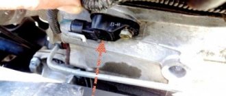
The sensor is located next to the crankshaft; the method of access to it depends on the specific vehicle. Sometimes its location is such that it is easier to get there not through the hood, but by lifting the car onto a stand. Sometimes (for example, in the case of the Land Rover Freelander), this will require removing the wheel and fender liner.
This component is located in a bracket, which is installed in the central area of the pulley on the generator drive. As a rule, on most modern cars it is not installed end-to-end, but with a gap of 1-1.5 mm near the structure of the toothed pulley itself.
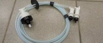
For ease of disconnecting and adjusting the DPKV, a 50-70 cm wire is connected to it, which has the necessary connectors for keys. To align and adjust the position, you only need to adjust the washer secured above the seat of the element itself. Adjusting the washer can be done either by you yourself or by specialists at a car service center - in any case, it will allow you to avoid early breakdown of the engine cylinders and significantly reduce fuel consumption.
Crankshaft position sensor
Crankshaft position sensor location
If a malfunction occurs in the crankshaft sensor, the vehicle’s on-board computer is unable to set a number of characteristics necessary for the operation of the ignition system:
- Calculate the amount of fuel required for injection;
- Determine the right moment for injection;
- Change the angle of rotation of the camshaft;
- Determine whether ignition has occurred or not (relevant for gasoline engines).
How the motion sensor works
The motion sensor is triggered when an object that emits heat appears
The sensor operates based on the recognition and analysis of various wave vibrations. The device can independently produce waves, then examines them after reflection from surrounding objects - this type is called active. The passive type receives vibrations from the outside and analyzes them. Most devices are produced in the form of combined modules.
The sensors vary depending on the type of pulsations used:
- tomographic (radio waves);
- infrared passive sensors;
- microwave detectors;
- photovoltaic (uses light);
- ultrasonic devices.
Each type has operating errors and occasionally gives a false alarm. The two varieties are combined in one installation to reduce the likelihood of misactivation, such as ultrasonic and infrared radiation. A complex solution reduces sensitivity; the device may not work in case of real danger.
Device selection rules
The price of equipment with advanced functionality is higher than the cost of basic models. The built-in photo relay saves electricity, because the light turns on when the motion sensor is triggered when the illumination on the street is below the set limit. The animal protection function eliminates false signals for the movement of cats and dogs.
When choosing, take into account the following characteristics:
- coverage angle;
- sensitivity of the device;
- detection distance;
- fixed speed parameter;
- no dead zone;
- operating voltage, operating temperature range.
The detection angle is usually 90 - 120° with a length of 10 - 15 meters, but there are models with a narrow but long horizontal sector. Devices detect speeds of 0.1 m/s, but movement that is too slow may not be detected. The dead zone is perceived using a lens located at the bottom of the tracking module.
Tools and materials for connection
Sensors of almost all models are designed for a load of 10 - 16 A. When the device power is more than 1 kW (current 4.5 - 5A), another switching device is installed in the circuit. A small magnetic contactor is used when connecting the sensor to the lamp via the distribution panel.
The amount of power supplied to the inductor must be equal to the mains voltage. In a standard system, the coil replaces the lamp, the lighting element is connected through the main contacts of the starter.
If a modular contactor is not used, high voltage field effect transistors are used. A pair of elements will allow you to pass a half-wave of alternating current in two courses. The control section of the circuit contains a rectifying diode with a voltage of more than 300 V to protect against breakdown and 2 resistors connected in series.
Motion sensor installation and configuration
Scheme for connecting the sensor to the lamp
Sensors that have a built-in switch are intended for wall installation. Separately purchased sensors are mounted on horizontal or vertical fences. Ceiling installation is often used because it covers a large area.
If the coverage radius is less than 360°, several devices are installed. In another option, models are mounted that are combined into a chain (Master/Slave mode).
If the detector is intended for a room with one entrance, a narrow sector will be enough to monitor the door. The device is adjusted to the maximum allowable start time of illumination.
For proper installation, you need to determine the area of the zone (usually under the device) where the device does not detect movement. Long-range sensors are installed in long corridors. Such devices often give false alarms because they monitor a large area.
Connection in the apartment
Connecting a motion sensor to lighting fixtures
The sensor starts sending a message to the owner when intrusion into the home is detected. The device in the security panel circuit signals the security company dispatcher to activate the rapid response team.
Two-wire sensors are installed in standard socket boxes. For this you need the elements:
- junction box;
- automatic 220 V;
- sensor;
- lamps.
The device is connected in the same way as a single-key switch, with the phase connected to the detector, then electricity is supplied to the lamp. The light-sensor circuit is mounted separately from the general wiring. The cable is led from the panel on the stairs into the distribution box inside the apartment, all three wires are marked, ground, zero, and phase are allocated. Then there is a two-wire cable to the sensor itself.
Outdoor connection
Street lights activated by motion sensor
Determined by the coverage area and installation location. The sensors differ in the parameters of moisture resistance and protection from negative atmospheric factors.
Degrees of protection:
- for open street space, devices with an IP protection rating in the range of 55 – 65 are used;
- Modules with similar IP 44 parameters are mounted under the canopy.
The air temperature recommended for the outdoor model is taken into account. There are many options when devices only work down to -20°C, then malfunctions occur.
There are 3 wires when connecting a three-wire device from the circuit breaker, to the lighting and to the sensor. The zeros are combined at one point, and the ground from the panel is connected to a similar wire on the lighting fixture.
Connection at the entrance
Motion sensors save energy in the entrances of high-rise buildings
Detectors are placed under the ceiling so that when opening doors the viewing angle is not disturbed. It is not recommended to install sensors in entrances above radiators.
The zero is connected from the power cable to the lamp wire and grounding is provided. The phase from the circuit breaker must be connected to the wire going to the sensor, the second wire supplies electricity to the lamp.
Settings are performed on the front panel by turning the corresponding flags:
- number 1 - automatic operation order;
- number 2 - select the sensitivity level according to the time of day;
- number 3 — sets the time to turn off the device after motion is detected.
You can connect a motion sensor with LED and energy-saving elements, but in this case the bulbs sometimes flicker.
How to check the VAZ-2114 DPKV for serviceability
To check the crankshaft position sensor, it must be removed and inspected for mechanical damage. If dirt is found on the sensor, the part should be thoroughly cleaned.
You can check the DPKV using an ohmmeter. A working sensor has a coil resistance of 550-750 Ohms. A multimeter is used to check the inductance of the winding, but you cannot be sure that the DPKV is working properly, even if all the readings coincide with the permissible parameters. In this case, the state of the magnetic core is not taken into account in any way, so an oscilloscope is best suited for diagnostics.
You can check the DPKV in any way, but it would be more logical to simply replace it immediately with a new one. If the cause is not in the sensor, you need to look further for the cause of the malfunction. The old DPKV can be put into storage; it will come in handy. The crankshaft sensor on a VAZ is quite inexpensive, so is it worth the hassle of measuring resistance and inductance? The price of DPKV ranges from 250-350 rubles, and on the road a spare sensor can be very helpful.
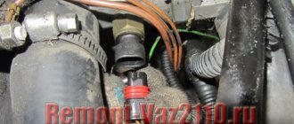
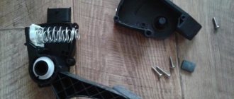
It's no secret that if the crankshaft position sensor fails, the car will only go further on a tow truck or in tow. The engine will simply be impossible to start, and the sensor cannot be repaired, only replacement. The sensor is not cheap, so before buying a new one, I recommend making sure that the cause of the malfunction is the DPKV, and not something else, or just a jamb in the wiring and connection chip of the sensor. If the diagnostics show that it is he who is to blame, we go to the nearest auto parts store and purchase a sensor, it looks like this:
To replace the DPKV on VAZ-2110, 2111 and 2112 we will need the following tool:
Socket wrench at "10".
A set of feeler gauges to set the gap.
Well, the new crankshaft sensor itself.
The sensor is located in close proximity to the crankshaft pulley. So, remove the block from the sensor by prying it with a screwdriver or any other handy tool. (you can just use your hands).
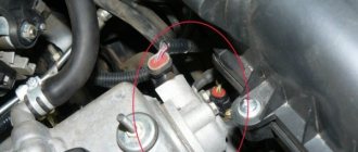
Then we take the prepared 10mm socket or open-end wrench and use it to unscrew the bolt that secures the DPKV to the engine.
Then we put the removed sensor aside, take a new one and install it in place of the old one, it is impossible to make a mistake during installation, it is installed in only one position. We screw back the sensor mounting bolt and take our set of probes. We will use them to adjust or simply check whether we have the required gap for the new sensor. The correct distance from the crankshaft pulley teeth to the sensor is 1 mm. plus or minus 0.41 mm.
If everything is correct, put the chip back in place and try to start the engine. If the distance is greater, we look where the jamb is and what got under the sensor, maybe just dirt. I have not yet encountered problems with the fact that the distance is less. Usually everything becomes normal right away.
Reference information: The CRANKSHAFT POSITION SENSOR (CPSE) supplies the controller with a signal of the rotation speed and position of the crankshaft. This signal is a series of repeating electrical voltage pulses generated by the sensor as the crankshaft rotates. Based on these pulses, the controller controls the injectors and the ignition system. The DPKV is installed on the oil pump cover at a distance of about 1+0.4 mm from the crankshaft drive disk (pulley). The crankshaft pulley has 58 teeth arranged around its circumference. The teeth are equidistant and spaced at 6° intervals. To generate a “synchronization pulse,” two teeth on the pulley are missing. As the crankshaft rotates, the teeth of the disc change the magnetic field of the sensor, creating induced voltage pulses. Based on the synchronization pulse from the crankshaft position sensor, the controller determines the position and speed of the crankshaft and calculates the moment of activation of the injectors and the ignition module. The DPKV wire is protected from interference by a screen connected to ground through the controller. DPKV is the most important of all sensors; if it is faulty, the engine will not work. It is recommended to always carry this sensor with you. Diagnosis of DPKV is described here. The PCV sensor is a polar device; if the wiring is broken, it should be connected observing the polarity. In reverse mode, the engine will not start.
Options and diagrams for connecting a motion sensor to a lamp
The motion detector can change the brightness of the light, turn the lighting on or off, regardless of motion detection. The device sends a command to the controller and he turns on the light in accordance with the requirements specified by the customer. There are toggle switches with built-in coordinators; such models can be installed in entrances, offices, and warehouses.
There are three wires of different colors on the body:
- output - red;
- zero - blue;
- phase - brown.
From the distribution panel, the control phase is connected to the load cable of the luminaire. If the wires are not connected in a junction box, the wires are inserted directly into the sensor body and combined at its terminal block. The neutral cables are twisted and tightened at the contact.
Without switch
Sensors must be configured so that they do not respond to small animals
The number of devices is not regulated. Upon entering at the beginning of the corridor, the first detector is triggered and the spotlight is turned on. After leaving the coverage area of the first sensor and before entering the area of the second, the lamps continue to illuminate the space. This continues until all installed elements leave the tracking zone, the light goes out after a specified time.
Sometimes there are false positives. This happens due to the action of heat flows if the element is located above a radiator or the sensor is surrounded by trees outside. Lighting is triggered by wind or faulty structural components. To determine the cause, you need to cover the sensitive eye with opaque tape.
With switch
Combined electrical automation reacts to the movement of people in the controlled area. The control unit is equipped with only a sensor or a key switch is installed. To save electricity, the switch is equipped with a photodiode detector of the light level in the room. During the day in sunlight the toggle switch will not operate.
The circuit of a motion device with a switch is universal; a single-key switch must be connected in parallel:
- the supply phase is turned on simultaneously to the detector and the single-key toggle switch;
- the second wire from the breaker goes to the lighting circuit (the outgoing core from the sensor).
The lamps start working at any time at the request of the owner of the house. The switch can be connected in series and simultaneously disconnect the entire circuit from voltage. If you turn it on again, the light will not light up immediately, but only after the time required for the motion sensor to scan and analyze the space in the coverage area.
Methods of checking in garage conditions
When your car's engine suddenly "dies", you need to remove the sensor and perform the diagnostics described below. If the motor continues to operate with signs of instability, perform the following manipulations:
- Thoroughly clean the device body with a rag moistened with an organic solvent - white spirit, turpentine or other degreaser. Pay special attention to the end facing the toothed pulley.
- Make sure the fastening is secure. Due to a loose screw, the sensor may move away from the metal teeth, as a result, the gap will increase and the generated pulse will weaken.
- Clean the connector contacts from oxidation.
- Inspect the wiring for melting or breakage.
If the above actions do not produce results, the crankshaft sensor is dismantled and checked with a multimeter in 2 stages. At the first, the resistance between the terminals of the device is measured, which makes it possible to verify the integrity of the induction winding. Clean the contacts, turn on the ohmmeter and check the resistance between them. Normal readings are in the range of 500–700 Ohms; if the turns are shorted, you will get a zero or reduced value; if there is a break, you will get infinity.
At the second stage, the performance of the element is tested according to step-by-step instructions:
- Switch the multimeter to voltage measurement mode, the maximum threshold is 200 millivolts.
- Securely attach the wires to the contacts of the sensor block (for example, with alligator clips).
- Take any metal tool - a wrench, a large screwdriver or something similar. Apply and tear it sharply from the magnetic core of the element, holding the body with your hand. The voltmeter should show voltage surges.
Advice. If the crankshaft sensor is OK, check the wiring with an ohmmeter. Perhaps the reason lies there.
Further actions are as follows: the broken crankshaft speed meter is replaced with a new one; the part cannot be repaired. The working sensor is installed back, maintaining the gap, and the troubleshooting continues in another place.
A few words about how to check the crankshaft sensor on the road when you don’t have a multimeter or other diagnostic tools. You will need 2 wires and an LED light bulb from any car lamp (for example, an interior lamp). For convenience, unscrew the element and connect the lamp to the connector, then apply a wrench to the magnet, as described above. A working sensor will cause the LED to flash.
Normal operation of a car engine is possible only if all actuators and sensors of the engine are operational. One of these controllers is the crankshaft sensor, the failure of which can lead to the inability to operate the car. You can learn more about what kind of device this is, how to check it and what malfunctions are typical for it from this material.