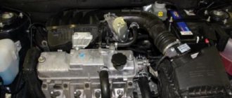
The procedure for replacing the DTOZH on a VAZ 2110-2112
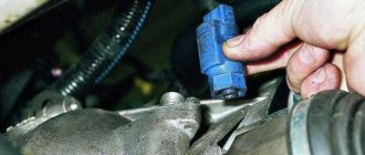
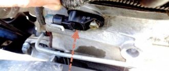
First of all, disconnect the negative terminal from the battery. After this, pressing the latch, disconnect the power plug from the sensor. The result is shown in the given picture below.
Before unscrewing the sensor, it is worth keeping in mind that the engine must be cool to avoid getting burned. Or you first need to drain the antifreeze or antifreeze from the system.
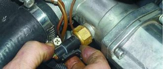
But I personally did everything on a cold engine, so I didn’t drain anything, and when unscrewing I just quickly closed the hole with my finger. As for unscrewing, a deep head with a ratchet is perfect for this task:
And as I said above, close the hole with your finger for a few seconds:
You need to have a new sensor on hand and immediately screw it into place. The maximum loss of coolant can be no more than 10 ml, if everything is done quickly, or even less.
Replacement is carried out with the same part with the same catalog number. In the next articles we will look at fault diagnosis and do-it-yourself testing. The price of a new DTOZ for cars of the tenth family is about 150-200 rubles.
Sources
- https://avtovx.ru/elektrooborudovanie/datchik-temperatury-salona-vaz-2110-74/
- https://remont-vaz2110.ru/zamena-datchika-temperatury-ozh/
Checking the sensors.
In order to check the DC, you need to have a multimeter, then follow a certain procedure:
- Turn off the sensor.
- We connect the red (positive) probe to the DC contact.
- We connect the black (negative) probe to ground.
- We fix a tube of suitable diameter onto the shaft in order to be able to rotate it.
- We switch the multimeter switch to low voltage measurement mode.
- It is necessary to rotate the shaft and observe the readings: as the speed increases, the readings on the multimeter display will increase. If the readings do not change, the sensor is faulty.
Another method does not require removing the sensor. To do this, you need to jack up one wheel so that it is at a distance from the ground and can rotate freely. After this, you need to connect a multimeter to the DC connectors. You need to rotate the wheel and observe the readings of the device. A change in voltage will also indicate performance.
Do-it-yourself replacement of the coolant temperature sensor
To replace the coolant temperature sensor, tools are required, which are presented in the table below.
Table - Tools and materials required to replace the coolant temperature sensor
| Name | Note |
| open-end wrench | "on 10" |
| Wrench | “at 19” |
| Head | “at 13” |
| Vorotok | With extension and ratchet |
| Screwdriver | Medium size, flat blade |
| Rags | For cleaning dirt without leaving lint behind |
In order to replace the DTOZH on a Chevrolet Niva, it is recommended to use the step-by-step algorithm of the instructions below.
- Work should be carried out with a completely cold engine. Therefore, before proceeding with the replacement, if the vehicle is just after a trip, then it is necessary to wait a time interval sufficient for the power unit to cool down.
- Secure the vehicle using the parking brake.
- Open the hood.
- Disconnect the vehicle's power supply. To do this, you need to remove the negative terminal from the battery.
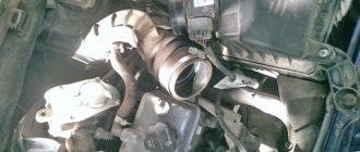
- For easy access to the temperature meter, it is recommended to remove the decorative protective casing of the power unit and the air filter housing.
- By pressing the clamps, remove the terminal from the coolant temperature sensor.
- Unscrew the meter.
- Remove the DTOZH.
- Install a new sensor.
- Reassemble everything in reverse order.
Replacing the outside air temperature sensor
You can’t call the ambient air temperature sensor an element of first importance, but it’s still nice how everything in the Chevrolet Niva works like a clock. There is one way to find out about the malfunction of this device for determining air temperature: compare the indicator on the car’s dashboard with another measuring device. But if you are stuck in a traffic jam in the summer, then you don’t have to be surprised when the temperature suddenly creeps up - all the devices are heating up.
Outdoor air sensor location
Also, when parked with the engine running or at low speed, heat affects the air sensor, and in the Niva Chevrolet it is not ventilated, so the data is overestimated.
This device is located at the bottom of the front bumper. If you stand facing the engine, the sensor is located in the bumper behind the lower right corner of the license plate. You can see through the hole in it.
But it won’t be possible to dismantle it right away; before that you need to complete preparatory steps. And we will talk about all this below:
- It is necessary to disconnect the negative terminal of the battery;
- Now you need to locate the sensor itself in the bumper holes;
- Gently pull it - the device itself should come out of the seat;
- Next you need to get it out, be prepared that it will pull the wire along with it;
- Replacement occurs as follows: the air sensor is disconnected from the plug by pressing the latch. Pull the plug carefully to avoid damaging fragile parts;
- Ready. All that remains is to install a new part; you can buy it at a car dealership or service center. As reviews say, non-standard devices can also be suitable for the Niva Chevrolet, but it is preferable to take original parts for the car;
- Installation proceeds in reverse order. Do not forget to check the operation of the systems after replacement.
Shniva without bumper with sensor
4.6. Thermal sensors
PETROL MODELS WITHOUT AIR CONDITIONING Check
| EXECUTION ORDER |
| 1. Power to the cooling fan(s) is supplied through the ignition switch and fuse. On gasoline engines without air conditioning, the fan is controlled by a temperature sensor installed in the radiator on the left side. On petrol engines with air conditioning and all diesel engines, the fans are controlled by a “bitron” sensor. |
| 2. The fan should turn on when the engine operating temperature is exceeded, i.e. a few minutes before the arrow of the engine temperature gauge enters the red sector or before the alarm lamp for exceeding the coolant temperature comes on. If the fan does not turn on, remove the wires from the temperature sensor, connect them together and turn on the ignition. If the fan starts working after this, the temperature sensor has probably failed and needs to be replaced. |
Removal
EXECUTION ORDER
1. The temperature sensor is installed in the radiator on the left side. The engine and radiator must be cold before removing the temperature sensor.
2. Disconnect the negative battery terminal. 3
Partially drain the coolant from the cooling system until the coolant level is below the sensor. Alternatively, you can not drain the liquid from the cooling system, and after unscrewing the sensor, very quickly install a plug in place of the sensor. In this case, care must be taken not to damage the radiator.
4. Remove the wires from the sensor contacts.
5
Using caution, unscrew the sensor from the radiator.
Installation
| EXECUTION ORDER |
| 1. Replace the O-ring before installing the sensor. |
| 2. The sensor is installed in the reverse order of removal. Tighten the sensor securely and refill the cooling system. |
| 3. Start the engine and warm up to operating temperature. If the temperature rises further, check that the fan is turned on with the sensor. |
PETROL MODELS WITH AIR CONDITIONING AND ALL DIESEL MODELS Check
| EXECUTION ORDER |
| The “bitron” sensor also controls the air conditioning system, and its functionality must be checked at a specialized Peugeot station. |
Removal and installation
| EXECUTION ORDER |
| 1. The “bitron” temperature sensor is screwed into the thermostat housing on gasoline engines or into the fuel filter housing on diesel engines, which is bolted to the left side of the cylinder head. The sensor can be identified by the brown color of the wire going to the sensor. |
| 2. Removal and installation are similar to those previously described for the radiator fan thermal switch. |
COOLANT TEMPERATURE SENSOR IN THE FUEL INJECTION CONTROL SYSTEM
Examination
| EXECUTION ORDER |
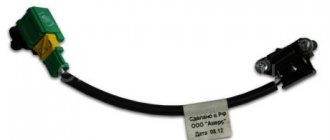
| 1. The coolant temperature sensor in the fuel injection control system is screwed into the thermostat housing, which is bolted to the left side of the cylinder head. The sensor can be identified by the green wire going to the sensor. |
| 2. The sensor is a thermistor. The electronic control unit (ecu) supplies voltage to the sensor and, by measuring the current flowing through it, determines the engine temperature. This information is used by the ecu to control the injector opening time (pulse width). On some models, idle speed and ignition timing are also determined by engine temperature. |
| 3. If the sensor fails, the ecu system enters backup mode, i.e. takes on a predetermined value that will allow the fuel injection system to operate, albeit with less efficiency. In this case, the corresponding warning lamp on the instrument cluster will light up, which means that you should contact a service station as soon as necessary. This sensor can be tested using special Peugeot diagnostic equipment. Do not attempt to test the sensor using equipment not intended for this purpose, as The ecu unit can be damaged. |
Removal and installation
| EXECUTION ORDER |
| The “bitron” temperature sensor is screwed into the thermostat housing on gasoline engines or into the fuel filter housing on diesel engines, which is bolted to the left side of the cylinder head. The sensor can be identified by the brown color of the wire going to the sensor. |
How to adjust
If you were unable to find the original sensor and had to buy an analogue, then the new resistor after replacement will lie, since it does not fit the parameters a little. This deficiency can be corrected. This is exactly why you will need pliers (2 pcs.). The order is as follows:
- Fill the fuel tank full.
- Turn on the ignition and remember the arrow readings (you can draw it on paper).
- Remove the negative terminal from the battery.
- Dismantle the FLS and slightly bend the lever with pliers (hold it firmly at the base with just one pliers).
- Then install the sensor in the tank, connect the battery and turn the ignition switch.
Your task is to ensure that the arrow coincides exactly with the unit scale (1). The operation must be repeated until the result is achieved. This usually takes 2-3 approaches.
Removing the crankshaft position sensor
The sensor provides the controller with information about the rotation speed and angular position of the crankshaft.
The sensor is of the inductive type and reacts to the passage of the teeth of the drive disk, combined with the generator drive pulley, near its core.
The teeth are located on the disk at 6˚ intervals.
To synchronize with TDC of the pistons of cylinders 1 and 4, two teeth out of 60 are cut off, forming a cavity.
When a depression passes by the sensor, a so-called synchronization reference pulse is generated in it.
The installation gap between the core and the tops of the teeth should be within 1±0.4 mm.
When the master disk rotates, the magnetic flux in the magnetic circuit of the sensor changes - alternating current voltage pulses are induced in its winding.
Based on the number and frequency of these pulses, the controller calculates the phase and duration of the pulses to control the injectors and ignition coil.
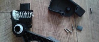
Removing and checking the sensor
1. Turning off the ignition, disconnect the sensor connector.
2. Use a Phillips screwdriver to unscrew the sensor mounting screw.
3. Remove the sensor from the camshaft drive cover bracket
4. The resistance of a working sensor should be in the range of 550–750 Ohms
Install the sensor in reverse order.
Video “VAZ phase sensor replacement”
This video talks about replacing the phase determiner (the author of the video is Ivan Vasilievich).
So, dear visitors, today we will tell you about the main sensors on the VAZ. Since the operating principle of injection engines in the AvtoVAZ line is the same, in principle we have put together a manual on the sensors that are installed on injection VAZs by the manufacturer, and have prepared a brief description of the operating principles and purpose of each of the sensors below. Indeed, in essence, the very principle of operation of an injection engine is the interconnected work of the “brains” (ECU) and various kinds of sensors; there is a constant exchange of information between them and, depending on the totality of certain indicators of the sensors, the controller prepares the mixture and ensures stable and correct operation of the engine.
So let's start with the crankshaft position sensor DPKV . (pictured above)
Without this extremely important sensor and if it malfunctions, the car simply will not start. DPKV generates signals to the ECU using a special toothed disk, on which, upon careful examination, you can see what appears to be a “missing” tooth; this disk is installed directly on the crankshaft. DPKV on VAZs is located on the oil pump cover. The sensor is quite reliable and its failure is rare. But nevertheless, if it fails, you will have problems. We recommend carrying it with you in the glove compartment just in case.
Let's move on. Another important sensor is the throttle position sensor TPS .
This sensor works in conjunction with the idle air control valve to determine how open the throttle valve is. If this sensor begins to fail or fails altogether, then we will not see a stable idle and the engine speed will live its own life. Dips may also be felt, the engine will pull jerkily, in general it is not pleasant.
Now we are presented with a phase sensor, or camshaft position sensor DPRV .
It determines the position of the camshaft. Not used on 8 valve engines of early injection VAZs. Participates in the formation of phased injection, that is, the desired injector of a particular cylinder works at the right moment. If the sensor is faulty, then the system works as if it were not there, and fuel is supplied in pairs-parallel mode, which leads to excessive consumption of gasoline with all that it entails. That is, you can drive, but it is not necessary; it is better to replace the faulty sensor.
Now let's look at the DD Knock Sensor .
It is installed directly on the engine block between the third and second cylinders. There are two types - resonant and broadband. These two types of sensors are not interchangeable. It corresponds entirely to its name, monitors engine detonation and, depending on the presence and strength of detonation, helps the “brains” adjust the ignition timing (ignition timing). If the sensor fails, the engine will slow down and gas consumption will increase.
Design of the internal combustion engine cooling system and components
The design of the VAZ 21213 Niva engine cooling system (as well as models 2131, 21214) is quite simple and has not actually changed since its development. The unit is of the liquid type with closed forced circulation of the cooler. On carburetor systems, the fan is mechanically driven. The injection circuit provides for 2 electric fans on the Niva 2131. The main components of the cooling unit circuit are:
- Mechanical pump. It is mounted in the cylinder block (BC) at the front, the impeller is partially immersed in the cooling liquid (operates using a belt drive).
- The thermostat is mounted to the right of (BC). Its pipes go to the radiator and water jacket.
- Radiator and two plastic tanks on both sides of the front of the engine.
- Fan with air diffuser on the inside of the radiator.
- An expansion tank with a cap and valves connected to the radiator with a pipe.
- Interior heating heat exchanger with tap.
Temperature control in the cooling system differs in different Niva models. On model 21213 with a carbureted engine, the sensor is built into the cylinder head with an indicator on the instrument panel. In the VAZ Niva 21214 (injection engine), the sensor is located in the pipe on the cylinder head.
It is also connected to a unit that prepares the fuel mixture relative to the temperature of the power plant and turns on the fans. Another difference from the general scheme is present in the VAZ 2131: the radiator is not equipped with a drain valve and is designed for constant circulation of antifreeze.
Russia, Penza 2020
Lada Niva (aka Lada 4x4) traces its history back to its creation in the 1970s, having managed to gain authority all over the world. A vehicle with all-terrain capability and comfort comparable to a passenger car. The car is popular not only in Russia, but also in Germany, as well as other countries in Europe and the world.
Fuse box - located to the left of the steering column under the instrument panel. Despite the fact that it’s 2020, and these cars have been fuel-injected for several years, they are nevertheless equipped with finger fuses.
Mounting block Lada 4×4
Location of standard wiring fuses
Fuses KSUD Lada NIVA
Operating principle
The cooling system of VAZ Niva models does not come into contact with the atmosphere in operating condition, and therefore requires pressure. The coolant is antifreeze with a freezing point of 40 degrees Celsius. The composition of the solution is water and ethylene glycol. The total volume of the cooling circuit is 10.7 liters. Antifreeze can boil after a temperature of +110 degrees Celsius.
The main functional unit in the system is the thermostatic valve, which distributes the coolant flow depending on the engine temperature. The thermostat, controlled by a temperature-sensitive sensor, regulates the direction of movement of antifreeze. A simplified work flow looks like this:
- Before the internal combustion engine warms up to operating temperature (+90 degrees Celsius), the cooler moves along a small circuit (interior heating radiator, thermostat, power plant) using a pump.
- The damper opens towards the large circuit where the radiator is located, at a temperature of + 80 degrees Celsius. Afterwards, virtually the entire cooler moves along a large circuit, mainly cooling through the radiator.
- The small ring is not blocked, but a minimum of antifreeze enters it due to pipes of a smaller diameter.
- In model 2121, the fan is mounted on the axis of the water pump and constantly directs the air flow to the (BC). Cooling fans in Niva 21214 and 2131 are paired with electric drive. They are activated alternately or together using a temperature sensor (switching temperature is about 100 degrees Celsius).
- When heated, excess antifreeze is sent to the expansion tank, increasing the pressure in the system, which reduces the boiling threshold of the coolant.
In summer and during transition periods in models with an injector, the movement of the cooler is limited by a special tap. The Niva Chevrolet model does not have such a blocker, so the heating is turned off by directing the air flow past the heat exchanger.
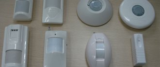
Temperature sensors used
The sensors used are classified into two types:
- with a temperature coefficient in the negative direction;
- with a positive temperature coefficient.
According to the purpose of use they are divided into 3 types:
- temperature indicator sensor;
- outside air temperature;
- liquid cooling temperature.
The first type (with a negative temperature coefficient) is most often used. If desired, you can install two structures at once: one as the main one, the other as an additional one.
The main component of the coolant sensor design is the thermistor. According to the principle of operation, this is a resistor that changes its resistance depending on the ambient temperature. It is protected by a metal case, on the surface of which cutters are applied. They are connected to the tail section, mounted from plastic. This is where the contacts that connect to the wiring are located. One contact is positive (comes from the electronic unit); the other is negative (connected to ground).
The principle of operation is that a constant voltage flow of 5 V is supplied to the thermistor from the electronic unit. As the temperature increases or decreases (depending on the type of sensor used), the resistance of the thermistor decreases, and the voltage across it decreases accordingly. As a result, when this voltage hits, the car’s electrical unit calculates the temperature of the engine and displays the desired indicator on the dashboard.
Purpose of the device.
A speedometer is installed on the Niva's instrument panel, which is necessary to display the current speed of the car. In the event of a malfunction, driving becomes difficult as most roads have speed limits that must be followed. In addition, a malfunction of the speedometer can affect the calculation of other data by the on-board computer. Based on the DS data, the required fuel consumption is determined and gasoline savings are ensured while idling.
Therefore, it is necessary to carry out diagnostics as soon as possible and identify the cause of the breakdown.
Operation of the cooling fan in fuel-injected cars
The operation of the fan unit for cooling the temperature in injection engines is assigned to an electronic motor controller. Its software is configured to trigger the engine overheat protection system in the temperature range from 100 to 105 degrees Celsius. If a defect occurs in the operation of the fan switch on in a VAZ with an injector, the controller “remembers” the error code and the fan starts working when the motor is turned on.
However, there are separate precedents when electronics in the form of a controller “reads” a defect and the fan installation may not begin to function when extreme temperature values are reached, i.e. above 105 degrees Celsius. Then, to test the circuit and the device, you need to disconnect the contact of the cooling fan switch sensor with the engine turned on.
If the circuit is functioning, then the fan unit should turn on and turn off with reverse action. If the circuit does not function, a test should be carried out to determine the suitability of the safety device and the technical readiness of the wiring and relay.
A quick check of the system is carried out as follows: we bridge the two contacts of the fan relay. If the product works in this position, then, without disconnecting the relay from the wire block, bridge the body of the relay and its contact using a “control”. In this position, the relay should function like the fan unit, which means that the controller or the relay connecting wire to the contact of this device is faulty.
If there is no sound of relay initiation, there is only one conclusion - the part requires replacement. If the fan unit does not start working when the relay terminals are closed, it is necessary to test the fuse for integrity and the power supply to the terminals of the fan unit. If power is supplied to one contact and not to the other, this may indicate defects in the EDC of the fan installation.