Where is the starter relay located on a Chevrolet Niva
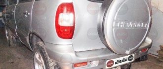
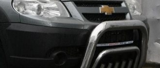
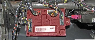
On the Shnivy, the relay is located on the right fender of the car between the battery and the starter. The device can be easily recognized by its appearance - it is a black block of a standard size with leads for 4 contacts and a grounding strip.
The fifth pin is used for mounting the part on a metal part of the car. It should be taken into account that the location of the relay is relevant not only for cars manufactured in 2005. The device is found here and in cars manufactured in:
- 2003;
- 2004;
- 2006;
- 2007;
- 2008.
Since 2009
On the car model after restyling, the location of the fuse has changed slightly. In versions like:
- 2010;
- 2011;
- 2012;
- 2013;
- 2014;
- 2015.
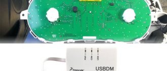
The relay was moved to a mounting block under the dashboard.
To access the unit, you will need to remove the protective casing and part of the console.
Chevrolet Niva fuse box. Detailed description
- damage to contacts (burnout)
- winding damage
- spring or armature wear
- destruction of the body or parts.
It is important to remember that the device is made in the form of a solid body, so its repair is not always possible or advisable. Therefore, it is better to replace the relay completely.
To understand when replacement is required, you need to pay attention to some characteristic signs when starting the car.
- When the engine starts, the relay does not return the bendix back, which causes the starter to rotate. At the same time, a strong buzzing sound appears under the hood.
- The starter works, but the engine does not start
- When you turn the key, you can hear the starter click, but it does not rotate.
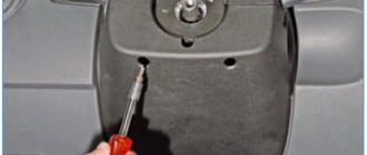
This block is located to the left of the steering column and is closed from below with a lid. To get to it, you need to tighten 2 screws, then press the top edge of the cover and gradually free it from all fasteners.
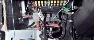
The block that appears will be held on a special bracket. The fuse diagram itself and the number of elements on it may vary depending on the configuration and year of manufacture.
photo of the fuse box in a Chevrolet Niva
| Fuse and relay mounting block |
| Most power supply circuits for vehicle electrical equipment are protected by fuses. The battery charging circuit, engine starting circuit, and generator are not protected by fuses. |
| The fuses and relays are installed in a block (pictures below), which is located in the car interior under the instrument panel on the left side of the steering column. The diagram of the internal connections of the mounting block is shown in Figure 9.2. |
| NOTE Depending on the year of manufacture and modification, the location of the fuses and relays may differ |
| Location of relays and fuses (up to 2009) |
|
| In table 9.1 gives the meaning of each fuse, but a specific car model may not have some of the circuits listed in the table. |
| Table 9.1 Circuits protected by fuses |
| Backlight lamps. Trunk light. Engine compartment lamp. License plate lamps. Front marker lamps |
|
| Location of relays and fuses (after 2009) |
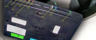
Mounting block of fuses and relays in the car interior: 1 — tweezers for removing fuses; 2 - spare fuses; K1–K8 - relay; F1–F20 —- circuit breakers
- Purpose of fuses
Relay purpose
| REPLACING FUSES AND RELAYS |
| Before replacing a blown fuse, find out the cause of its burning and eliminate it. When troubleshooting, look at the information listed in the table. 9.1 circuits that this fuse protects. |
| RECOMMENDATION Always carry a set of spare fuses with you. |
| Do not replace fuses with jumpers, fuses rated for different amperages, or a homemade jumper. This may cause damage to electrical appliances and even cause a fire. |
| 1. Remove the two screws securing the fuse box cover. |
| 3. ...remove the fuse. |
| 5. Install new fuses and relays in the reverse order of removal. |
| The injection system relay and fuse box is located under the instrument panel in the passenger foot area. |
| It is not allowed to replace a blown fuse with a fuse of a different rating or a homemade jumper. |
| The cooling fan fuses are located in the injection system fuse and relay box. |
| 1. To replace fuses, remove the fuse box cover by unscrewing the screw securing it. |
| 3. ...right fuses. |
| 4. Inspect and replace blown fuses. |
Replacing ECM fuses and relays Replacing windshield wiper relay
Video
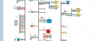
The connection diagram for electrical consumers of a Chevrolet Niva car is a set of parallel-connected circuits, each of which is protected by a fuse.
This distribution allows you to create circuits designed for their rated current value. For convenience, all fuses and relays are displayed on a single panel.
The Chevrolet Niva fuse box is located under the center console on the driver's side.
The Chevrolet Niva mounting block combines a fuse and relay panel.
To get to it, you need to unscrew the screws securing the cover under the steering column, and then pull this cover towards you. The purpose of the mounting block elements depends on the year of manufacture of a particular model.
In 2009, the Chevrolet Niva underwent restyling, therefore, along with other changes, the functions of the protective devices also changed.
Each protective device ensures the integrity of a separate circuit consisting of one or more consumers.
| Fuse (current, A) | Protected Circuits |
| F1 (5 A) | Backlight lamps. Trunk light. Engine compartment lamp. License plate lamps. Front marker lamps |
| F2 (7.5 A) | Low beam lamp (left headlight). Electric headlight corrector. Corrector motor gearbox |
| F3 (10 A) | High beam lamp (left headlight) |
| F4 (10 A) | Left fog lamp |
| F5 (30 A) | Power window relay. Electric windows |
| F6 (15 A) | Electric door lock control unit |
| F7 (20 A) | Cigarette lighter. Horn relay. Sound signal |
| F8 (20 A) | Rear window heating relay (contacts). Rear window heating element |
| F9 (20 A) | Glove box lighting lamp. Windshield wiper relay. Windshield wiper switch. Windshield wiper motor. Headlight wiper relay (contacts). Electric motors for headlight cleaners. Headlight washer motor |
| F10 | Reserve |
| F11 (5 A) | Rear position lamp. Instrument lighting control |
| F12 (7.5 A) | Low beam lamp (right headlight). Corrector motor gearbox (right headlight) |
| F13 (10 A) | High beam lamp (right headlight) |
| F14 (10 A) | Right fog lamp |
| F15 (20 A) | Exterior mirror control unit. Exterior mirror control motors |
| F16 (10 A) | Relay-breaker for direction indicators and hazard warning lights (in hazard warning mode) |
| F17 (7.5 A) | Individual lighting lamp. Immobilizer warning lamp. Brake light bulbs. Additional brake signal. Interior lighting |
| F18 (25 A) | Reversing lamps. Electric heater fan. Windshield washer motor. Rear window heating relay (winding). Rear window wiper relay. Rear window wiper motor. Rear window washer motor. Door lock control unit |
| F19 (10 A) | Relay-breaker for direction indicators and hazard warning lights (in direction indication mode). Devices. Differential lock indicator lamp |
| F20 | Rear fog lights |
Since 2009, the appearance of the mounting block and the relative position of all its components on it have changed. The appearance of the relays and their purpose have changed.
The purpose of the protective elements installed in the same position has also changed.
| Fuse (current, A) | Protected Circuits |
| F1 (5 A) | License plate lights, side light lamps in the left headlight and left rear light, engine compartment lamp, side light indicator lamp |
| F2 (7.5 A) | Low beam lamp (left headlight) |
| F3 (10 A) | High beam lamp (left headlight), high beam indicator lamp |
| F4 (10 A) | Left fog lamp |
| F5 (30 A) | Power window relay, front power windows |
| F6 (15 A) | Cigarette lighter |
| F7 (20 A) | Horn Relay, Horn, Trunk Lamp |
| F8 (25 A) | Heated tailgate glass element, heated tailgate glass relay, heated outside rear view mirror elements |
| F9 (20 A) | Heated tailgate switch, windshield wiper relay, windshield wiper motor, windshield washer pump, right steering column switch, glove compartment lamp, reverse lamps |
| F10 (20 A) | Remote control unit for electrical accessories (door locking) |
| F11 (5 A) | Side light lamps in the right headlight and right rear lamp, instrument lighting brightness control |
| F12 (7.5 A) | Low beam lamp (right headlight), gear motors for headlight beam control |
| F13 (10 A) | High beam lamp (right headlight) |
| F14 (10 A) | Right fog lamp |
| F15 (20 A) | Outside mirror control unit, electric outside rear view mirrors, heated seat control unit |
| F16 (10 A) | Relay-breaker for direction indicators and hazard warning lights (in hazard warning mode) |
| F17 (7.5 A) | Interior lamps, anti-theft system status warning lamp, brake lights, additional brake light |
| F18 (25 A) | Heater fan |
| F19 (10 A) | Relay-interrupter for direction indicators and hazard warning lights (in turn signal mode), instrument cluster (except for engine management system malfunction warning lamp), starter relay |
| F20 (7.5 A) | Fog lamps in the rear lights, anti-theft control unit, buzzer |
Principle of operation
The blocking device is responsible for turning on the device strictly at a certain moment. After turning on the ignition, a signal is sent to the starter and the bendix is activated, the armature of the electric motor engages with the flywheel and begins to rotate. An additional relay involves cutting off power to the motor after it has been successfully started.
The starter turns off after the engine starts running, which would be impossible if there was no blocking. The protective insert also prevents overloads and fires in the car.
Main block with fuses and relays
This block is located to the left of the steering column and is closed from below with a lid. To get to it, you need to tighten 2 screws, then press the top edge of the cover and gradually free it from all fasteners.
The block that appears will be held on a special bracket. The fuse diagram itself and the number of elements on it may vary depending on the configuration and year of manufacture.
photo of the fuse box in a Chevrolet Niva
For cars manufactured before 2009
Scheme - option 1
Scheme - option 2
Explanation of fuses
F1 (5 A) - license plate lamps, instrument panel lamps, indicator light on the dashboard, engine compartment lamp, additional brake light lamp, left side lamps.
If any of the listed lamps do not work, check this fuse and the lamps themselves, their connectors and wiring.
F3 (10 A) - high beam in the left headlight, indicator lamp for turning on the high beam headlights on the dashboard . Similar to relay K5.
F4 (10 A) - backup fuse.
F5 (30 A) - front door electric windows and their relays . If, when operating the power window, the window goes down but not up (or vice versa), check the button on the door. When lowering and raising, the polarity and direction of rotation of the motor are different. It could also be a problem with the window lift mechanism. To get to it, you need to remove the door trim. Check that the mechanism does not bite anywhere and that the gears are intact, without broken teeth. If there are problems, you can replace the entire power window drive with a new one.
F6 (15 A) - door lock control unit . If one or more doors stop opening, check this fuse. The issue may be in the central locking, control unit, as well as the mechanisms themselves, rods and door locks. If you have no experience, it is better to contact a car service.
F7 (20 A) - sound signal and its relay, cigarette lighter . If the horn does not work, check this fuse, the steering column contacts and the wiring; the contacts may have oxidized and the wiring may have become frayed. Also check the horn itself, you can replace it with another one, for example, a two-tone one from Volga. If the cigarette lighter does not work, check the wiring and its contacts. The white wire is responsible for the backlight, the red and black wires go to the cigarette lighter contacts. Do not insert non-standard connectors into the cigarette lighter, they may cause a short circuit. If the connector in the cigarette lighter moves to the sides, it is better to use a splitter and insert this connector there.
F8 (20 A) - rear window heating element and relay (contacts) . Similar to relay K7.
F9 (20 A) - rear window heating relay coil, additional relay, rear window wiper motor, wiper and washer switch.
F10 (20 A) - backup fuse.
F11 (5 A) - right side lamps.
F12 (7.5 A) - low beam in the right headlight, gear motors for headlight range control . Similar to relay K4.
F13 (10 A) - high beam in the right headlight . Similar to relay K5.
F14 (10 A) - backup fuse. F15 (20 A) - backup fuse.
F16 (10 A) - turn signal and hazard warning light switch (in emergency mode) . Similar to relay K3.
F17 (7.5 A) - interior lighting, individual backlight lamp, brake light lamps, engine control system malfunction warning lamp . If the brake lights do not work, check this fuse, the lamps themselves, their connectors, usually the problem is bad or oxidized contacts. Also check the operation of the brake light switch located near the brake pedal.
F18 (25 A) - heater electric motor and its switch . If the stove blows cold air, the problem may be in the hot air damper, the cable to which comes from the regulator under the casing not far from the gas pedal. The coolant level must be within acceptable limits. If the heater doesn't work or blow at all, it could be the heater motor. Also check the heater switch and its contacts.
Repair manuals
Due to the design features, the relay on most cars is a block module that cannot be repaired. It’s the same here – they cannot be disassembled and are in a sealed case.
The usual repair procedure involves diagnosing the entire circuit of the device and replacing the relay with a known good one.
Shniva won't start, starter relay clicks
If the starter does not turn, but the relay clicks, the problem should be looked for after it. The technicians first check the bendix and the solenoid relay. These components are also not subject to repair; if a breakdown is detected, they should be replaced.
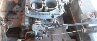
Replacing the starter relay Shnivy
To remove the retractor toggle, you will need to perform an operation.
- Place the machine on a level surface and securely fix it.
- Disconnect the power terminals from the battery.
- Using a screwdriver or a No. 8 wrench, unscrew the starter power wires.
- Under the car, you will need to unscrew the nuts of the starter mounting studs from the engine housing.
- Next, the starter is removed from its seat and dismantled from the car.
- The spring clamps of the retracting element are dismantled.
- Installing the new part and reassembling is done in reverse order.