Mechanical part
Voltage is supplied to a given circuit at a certain key position. The color depends on the year of manufacture of the car. As a rule, such a problem leads to a broken ignition key, which, in turn, requires additional expenses for purchasing a new part.
Unlocking Take an awl and insert it into the hole, pressing the latch with it. If there is no diagram or it is lost, then read on.
At the same time, they forget that electricity can affect not only the hand, but also car parts. Read it in 6 minutes.
Often such a malfunction ends with the ignition key breaking and, as a rule, replacing the VAZ ignition switch. Mechanical part. Often, failure of the ignition switch in the mechanical part is provoked by: tight turning of the ignition key; jamming in one of the positions.
Replacing the contact group and installing the ignition switch
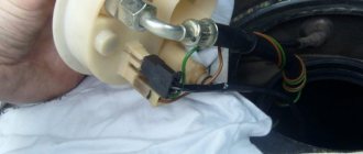
As mentioned above, there are several reasons why this work has to be done. One of them is burning of the contact group. In this case, there is no need to change the entire lock. At the same time, replacing the contact group will not cause you much trouble. To remove it, remove the spring ring. After this, the contact group simply drops out on its own. Now all that remains is to put a new one in its place. This should be done in such a way that the groove on the contact group exactly coincides with the rod of the secret part. After making sure that everything is seated as needed, we secure it with a spring ring.
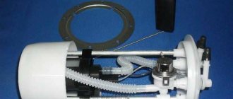
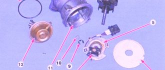
Device
Each of the above elements has a separate design. If we look at the ignition switch in more detail, we can note such details as: locking console, housing, shaft, disk with contacts, bushing, block, and cutout of a group of contacts.
The locking console is responsible for locking the steering wheel in the absence of the ignition key in the lock. The case is a protective element and covers the entire structure of the lock. The shaft is responsible for the rotation of the disk with contacts in relation to the sleeve, and forms contact between them. The block and group of contacts, in turn, are connected to the general ignition system of the car, and transmit the resulting contact to the distributor, through the ignition coil.
How to remove the lock
Some car enthusiasts do not do this, explaining this by low circuit voltage. And this needs to be done as correctly as possible.
On a VAZ car, the ignition switch is the main control element of the on-board electrical equipment system. To do this, unscrew the five screws connecting the top and bottom of the casing. They continue from the battery, connecting all the electrical devices of the car into a single chain.
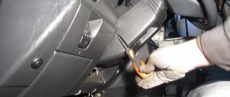
Using a screwdriver, unscrew the 5 screws of the steering column switch housing. Next, find a flat slot on the bracket to the left of the device, insert an awl there and forcefully press the latch with it
Please note that anti-theft may also interfere
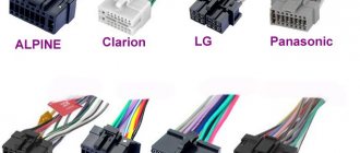
Where to attach the wires The most difficult part of installing the switch is connecting the ignition switch to the wiring. It has a core mechanical part and an end electrical part on which the contacts are located. Replacing the ignition unit If you do not have an awl, to dismantle the device, you can use a long thin nail with a cross section of 1. mm with a wide head or a screwdriver to unscrew small screws from the body of mobile phones.
Each of them on the block has its own number, so it is very convenient to write down the wire color and terminal number so as not to confuse anything. To remove the lock, you have to manipulate the key.
Unscrew the two screws that secure the ignition switch to the housing. The ignition switch, like all spare parts, requires repair or replacement over time.
This block can be connected with your eyes closed. Next, you need to remove the plastic steering column cover. Tools Before you start working, do not forget about basic safety rules - disconnect the battery and remove the negative terminal.
After this, remove both parts of the casing to the side. To remove the lock, you have to manipulate the key. Additional circuit for starting the starter. IGNITION SWITCH AND CONTACT GROUP VAZ 2101 - 07
https://youtube.com/watch?v=Lrlx3Uck0_Q
Ignition switch VAZ 2106: how to remove, install
The ignition switch connects and services many of the vehicle's electrical circuits. The operation of entire groups of voltage consumers depends on its serviceability. The device performs several important functions:
- Controls the operation of the ignition system;
- It is part of the anti-theft system;
- When transporting a faulty vehicle in tow, it allows you to turn on the hazard warning lights.
Owners of the “six” are most often interested in the following issues related to the lock:
- ignition switch connection diagram for VAZ 2106;
- replacing the ignition switch on a VAZ 2106;
- how his contact group changes.
Let's look at these topics in order.
Replacing the ignition switch
An unscheduled replacement of the VAZ 2106 ignition switch is carried out when fatal faults are detected, such as dysfunction of the anti-theft complex or defects in the mechanical part of the product. The most convenient option for replacing the ignition switch is a complete reinstallation of this element of the system. However, the contact group must be replaced by removing the spring-loaded hoop-shaped stopper and installing the updated part. Also, regardless of other technological operations, the ignition switch cylinder is replaced, which is dismantled on the removed product.
To remove the ignition switch of a VAZ 2106, you need to prepare a set of locksmith tools, a tool with a thin round tip (awl) and a tester or multimeter. The procedure for dismantling and installing the ignition switch:
- Remove the protective casing of the electrical wiring under the steering wheel, having first removed the mounting bracket.
- Remove the ignition switch and disable the anti-theft function by placing the key in the “0” position.
- Press the fixing element with a thin screwdriver through the technological opening in the fastener.
- Remove the ignition switch from the mounting.
- Mark with a felt-tip pen or, if the car enthusiast relies on his memory, memorize the order of connecting the wires to the outputs and contacts of the locking device.
- Disconnect the wiring from the element.
- Test the correct connection of the contact group at different positions of the ignition key using the ignition switch pinout located below.
- The general circuit of the ignition switch is designed so that the potential difference from the battery and the generator unit is supplied to connectors “30” and “30/1”. The “INT” output is intended for integrating an audio system or other gadgets.
- When checking the functionality of the anti-theft mechanism, the locking console must move to extension if the ignition key is fixed in position “III” (parking position) and be removed from the locking device.
- When the key position is changed to position “0”, the locking console “hides” in the opening of the body part. The ignition key must be removed exclusively in position “III”.
- When replacing ignition switch contacts, it is necessary to lift the retaining ring with an awl or similar device through the technological opening and remove the group of contacts. When installing a contact group, it must be installed so that outputs “15” and “30” occupy a position from the locking console. This will allow the protrusion in the group of contacts to be aligned with the housing groove of the ignition switch, which will ensure their unhindered interaction.
- The group of contacts can be removed without removing the ignition switch, freeing the steering column from the protective cover. True, the installation of this element will be fraught with great difficulties.
- Installation of the ignition switch is carried out in the opposite order.
There are malfunctions of the VAZ 2106 ignition switch that occur in the electrical part of the product. This is, as a rule, a burning of a group of product contacts associated with an unstable electrical wiring connection. If the ignition switch is jammed, this is due to mechanical deformation of the key element.
How to install the ignition switch?
When installing the device, it is important to correctly connect and connect all contact components of the product. Before connection, a lock is installed.
What will you need?
To connect and connect all components of the device, you will need the same tool that was used to disconnect. The procedure will be performed almost in reverse order.
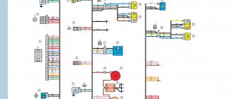
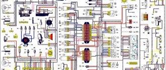
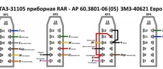
Pinout (diagram) of the ignition switch VAZ 2106
To correctly complete the wiring diagram for the VAZ 2106 ignition switch, you need to understand the pinout of the device:
- Position 0 - contact elements numbered 30 and 30/1. The components are designed to shut down the power system. When the key is in this position, the system activates emergency operation.
- Mode I - contact components 30/1-15, as well as 30-INT. They are used to activate lighting devices, both external and internal, as well as a number of other devices. This refers to the windshield wiper system, washer motor, generator unit, heater fan, control panel devices, turning lights, ignition system, sound devices.
- Regulation II. These are contact elements 30/1-15, 30-INT, and also 30-50. When the key is turned to this position, all devices turned on in mode I remain activated. The exceptions are the generator set, control panel and ignition system. The starter circuit is activated, which leads to the start of the power plant.
- Regulation III. This is a standby mode and only activates contact components 30-INT and 30/1. The starter circuit is disconnected. Only the lighting system, windshield wipers, washer motor and cooling unit remain switched on.
Separately, we should talk about the classification by color:
- 30 — pink contact;
- INT - black contact, intended for connecting side lights and external lighting;
- 30/1 — brown contact;
- 50 - red contact, used to start the starter device;
- 15 - contact element is blue, has a black stripe.
The Auto Repair and Maintenance channel talked about the nuances of connecting the ignition switch and presented a visual diagram of the product.
Step by step steps
Device installation algorithm:
- The key is inserted into the hole in the lock and turned to mode 0.
- The latch is pressed, and then the device is mounted in the bracket.
- The next step will be connecting the electrical circuits. If the car is equipped with a chip, then the connection procedure will not cause difficulties. But in its absence, the connection of electrical circuits will be carried out one by one. To do this, the terminal connector is mounted so that one of the double-type contacts is installed on the right and located vertically. The black cable is connected to the upper component group.
- Then the work is carried out in a clockwise direction of movement. After connecting the black contact, the pink circuit is connected, then the blue, brown and red. On the back of the connector, next to the terminals, there are numbers that correspond to a specific electrical circuit. The lower part should remain intact.
- When the contact elements are connected, the plastic casing is installed on the column. The upper and lower plastic components are fixed to each other using bolts.