Characteristics of Swat car radios
You can find out below what characteristics this device differs from similar ones, what disadvantages it has and what advantages it has.
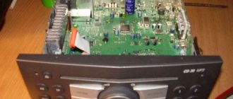
Appearance, equipment and characteristics
This brand has existed relatively recently.
It was launched on the market as a new version of the standard Intro/Incar multimedia devices and has the following characteristics:
- Power. The chip in the device is a regular, standard one, but it can easily distribute sound to 4 speakers.
- Signal to noise ratio. This parameter indicates that the higher the noise, the better and higher quality the sound. Radio tape recorders of this brand are not much different from well-known, popular brands that have been proven over the years.
- Equalizer. It's easy to adjust the sound, because the adjustment is quite primitive. You can activate the noise reduction system and reset it to any of the musical styles, for example, rock. The option can be disabled or reset.
- Radio. This radio has not advanced much in popular gadgets such as RDS, but it can find up to 18 stations.
- The car radio also has outputs: USB port, SD slot, AUX input.
- The device only plays MP3 format, but this is perhaps not such a big minus, because in fact you can find quite a lot of files of this format on the Internet. The ID3 metadata format is used only in the Swat MEX-2430 model.
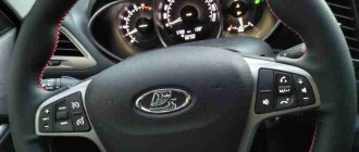
- Car radios of this brand, depending on the model, have different button illumination, which allows the car enthusiast to choose a device depending on the illumination of the car’s dashboard. As mentioned above, there is a model (Swat MEX-2430) that has the ability to change several colors and also do it automatically.
Every year the company is developing and car radios are being transformed, now you can buy a row 2 DIN Universal radio, and this says a lot, and first of all, that these multimedia devices are popular.
One purchase includes:
- car radio;
- wires for connection;
- user guide;
- warranty card and packaging (video author - Radar Master).
The lineup
This car radio is new to the market, and therefore the model range is not particularly diverse and huge. But of course there is a choice.
- SWAT DEX. This radio is different in that it has a built-in drive for playing music from discs. There is a digital radio tuner and other characteristics that were described above: the ability to store up to 18 radio stations, a USB and AUX input, and, of course, a non-removable panel.
- SWAT SHR. This radio has CD and DVD players, support for multiple memory cards, the ability to play DVD-video, MP3, MPEG4, WMA, DivX, JPEG formats, and also has Bluetooth support.
- SWAT MEX. Much has already been said about radios of this model. Basically, they have the ability to play MP3, support WMA, MP3 formats, and have a USB input and audio output. Ability to preset equalizer 3.
Pros and cons of devices
Regarding the pros and cons, we can say that there are both. After all, it’s a cheap car radio that also doesn’t accept ID3, which is not at all suitable for Apple owners. Among other things, the radio does not have a disc drive and a weak equalizer.
But those who value convenience may like this radio. After all, it contains the most necessary set for listening to high-quality music, and unnecessary settings, “useless ballast” - everything is discarded to make the device cheaper and simpler. And, perhaps due to the fact that there is nothing to break in the car radio, it will last quite a long life.
Among other things, you can purchase a more expensive model: with a navigator, support for various formats, including MP5, MKV, AVI, MOV, MP4, ASF, FLV, PMP, RMVB, MPG, VOB. The main thing is to know what exactly to look for.
Markings and types of connectors
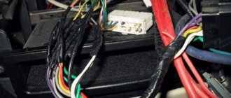
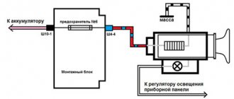
To answer your silent question about what kind of connectors there are in car radios, I must answer that most modern car radios are equipped with two standard connectors, designated by the abbreviation “ISO”. Each of these connectors is designed as an eight-pin rectangular plug, sometimes they are combined into one housing (see photo).
Car radio ISO connector pinout
One of the connectors carries “power” circuits, that is, current consumption sources are connected to it, and is designated in the diagrams as a connector under the letter “A” and is colored brown. The second connector is intended for connecting the car’s acoustic system, in other words, speakers. Unlike the previous one, it is made in black and is designated on electrical circuit diagrams as connector “B”.
What connectors do car radios have?
Sometimes there are car radios with three connectors, but this is the exception rather than the rule. The same exception as non-standard connectors, which still have wiring with standard markings and in any case allow you to connect the wires of a standard speaker system with non-standard “connections” in at least two ways. So:
- “Skolkhoz”, namely, cut off the non-standard plug and overlap the wires, which “is not very good”, since over time the twist will become loose due to oxidation/shaking and, in the best case, you will have to do all the work again while simultaneously replacing the fuses.
Pinout of ISO connectors for car radios
- Buy an adapter (the price of which is in no way close to the amount of work that the method described above includes) and, without any problems, decorously/nobly, connect the car radio with other elements of the acoustic circuit of your car.
Operation and Installation Guide
The car radio is installed in a standard place for 1 DIN or 2 DIN. If there is no compliance with these sections, then you can use an adapter to connect it to the fixing frame. The device is connected using an ISO adapter or directly using a 16-pin “Euro connector”.
Price issue
In the photographs below you can see the appearance of the car radios, as well as their price.
You decided to connect the radio yourself, but when you saw the number of wires coming out of it, you were afraid that you couldn’t handle it? In fact, there is nothing wrong with this, and in this article we will figure out how to connect a radio in a car.
What can you encounter if your car radio is not connected correctly?
This is not to say that to properly install a radio, you don’t need to have any skills at all. It is advisable to have at least initial experience in connecting electrical devices, but this is not a prerequisite; following the instructions, a person can complete the installation without any experience. To understand whether everything was done correctly, it is worth monitoring the operation of the radio. A sign of an error will be the presence of the following factors:
- The radio turns off when the volume is increased.
- When you turn off the ignition, the radio settings are lost.
- The radio drains the battery when turned off.
- The audio signal is noticeably distorted, especially when listening at high volumes.
In very rare situations, it is not the person who connected it who is to blame, but the seller who sold the low-quality product. Of course, this option cannot be ruled out, but you will still need to double-check the connection diagram.
Size and types of car radios
Universal radios have a standard size, it can be 1 – DIN (height 5 cm, width 18 cm) and 2 DIN. (height 10 cm, width 18 cm.) If you change the radio from large to small (from 1 – DIN, to 2 – DIN), you will need to buy a special pocket that will cover the missing din. In terms of connection, these radios all have the same connector, its name is ISO or it is also called a Euro connector.
1-DIN radio
Radio size 2 - DIN
Pocket for installing radio 1 -DIN
Standard radios are installed on cars from the factory and have a non-standard size; in this case, there are two options for installing the radio. The first is the simplest, you purchase the same standard radio and install it, it fits in size and connects to the standard connectors. But the cost of these radio tape recorders is often inadequate. And if you find a budget option, then with 100% probability it will be from China, which is not particularly famous for its sound quality and reliability. The second option is to install a “Universal” radio in place of the standard one, but for this you will need an adapter frame, which is an adapter from the standard sizes of the radio to the universal ones, i.e. 1 or 2-DIN. the frame plays a decorative role, covering extra holes.
Hint for TOYOTA owners. In most cars of this brand, the standard radio has a size of 10 by 20 cm. In this case, you can look for “Spacers for Toyota radios”, they are 1 cm in size and you can easily install a standard-sized radio, i.e. 2 – DIN, to install 1 – DIN you will still need to buy an additional pocket.
Connecting the radio.
There are many cars, and each of them can use its own set of connectors to connect such equipment. Basically, there are three options:
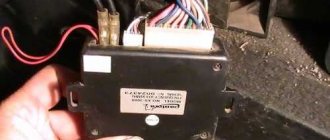
- Option one is the most favorable. You already have a chip in your car to which everything is connected correctly, i.e. All speakers, power wires, antennas are connected to this chip, and everything is connected correctly. This happens but, unfortunately, very rarely. This means that you are lucky, you just connect your brand new radio to this chip, and everything works for you.
- The necessary wires are routed and connected, but the socket on the radio is different from the plug on the car.
- There is no power lead out or it was done incorrectly.
With the first point, everything is almost clear. When the device socket does not match the connector, you will need to use an adapter. Despite the fact that these connectors are most often individual for each model, many companies practice supplying a separate ISO adapter. If there is no adapter or its format is not suitable in this case, you can either purchase such an adapter or twist the wires yourself. Of course, the second step is longer, more complex and riskier. Only technical centers that have experience in such procedures do this, so before you connect the radio in your car in this way, you need to think about everything very carefully.
Connecting the ISO adapter - Toyota
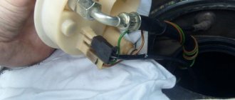
If you want to do the twisting yourself, you need to check the correspondence of the wires on the radio and the car connector. Only if the colors match can you disconnect the battery and disconnect the car and audio system connectors.
How to connect a car radio without getting tangled in the wires? It is recommended to bite off the remaining part after attaching the connector to the radio. All connections are soldered and insulated. If the wires do not match, you will need to check them using a tester or multimeter, as well as a 9-volt battery; you may also need to lay those wires that are not enough for connection. Ringing is necessary to determine the polarity of a pair of wires. When testing a loudspeaker, the wires are connected to the battery, after which you need to look at the position of the diffuser - if it extends, then the polarity is correct, if it retracts, you need to correct the polarity to the correct one. Thus, each wire is marked.
Connected ISO connector
ISO - connector
Decoding the color code of wires
1. The negative of the battery is painted black, the wire is marked GND. 2. The battery positive is always yellow and is marked BAT. 3. The plus of the ignition switch is designated ACC and is red. 4. The wires of the left front speaker are white and marked FL. The minus has a stripe. 5. The wires of the right front speaker are gray and marked FR. The minus has a stripe. 6. The left rear speaker wires are gray and marked RL. The minus has a stripe. 7. The wires of the right rear speaker are purple and marked RR. The minus has a stripe.
How to properly connect a car radio?
First you need to purchase all the necessary wires. The wires must be made of pure oxygen-free copper and have silicone insulation. The yellow and black wires are power wires, the cross-section of these wires should be more than 2.5mm. For speaker wires and AAC (red), wires with a cross section of 1.2 mm are suitable. and more. Try to avoid a large number of twists, the ideal option is where there will be none at all, because... twists add extra resistance and this negatively affects sound quality and volume.
Connection diagram for radio and speakers
All radios have a black wire for the battery negative, yellow for the battery positive and red for the ignition switch positive. The car radio connection diagram is as follows - first it is better to connect the yellow and black wires, moreover, to the battery, which will allow you to get high-quality sound.
You will definitely need to install a fuse at a distance of 40 cm. The fuse must correspond to a minimum value of 10 A. The red wire is connected to the circuit, which is powered after turning the ACC key. When connecting the red and yellow wires together to the battery positive, the radio will not depend on the ignition, but the battery will discharge faster. Powerful radios have four pairs of wires, each of which has its own marking. When connecting a radio to a car, the polarity may be incorrectly determined - nothing bad will happen here, unlike grounding to minus to ground. The speakers have either two terminals, basically the speaker connection diagram is as follows: the wide terminal is a plus, and the narrow terminal is a minus.
If you want to replace not only the radio but also the acoustics, we advise you to read the article “”
What are the wires used for and where do they go?
For the correct connection to work, it is imperative to know the colors of the wires and their designation. The diagram of the radio wires by color is shown in the photo. On all cars and radios (Pioneer, Sony and Kenwood and others) it is customary to use a certain color to indicate the identity of the wire. It is worth noting that the radio wires differ in color and in the presence or absence of a strip. So, all wires with a stripe are a minus, and those without a stripe are a plus.
- Battery negative – black;
- Battery plus – yellow;
- Ignition plus – red;
- Left front speaker – white and white with stripe;
- Right front speaker – gray and gray with stripe;
- Left rear speaker – green and green with stripe;
- Right rear speaker – purple with a purple stripe;
- Antenna – blue;
- Amplifier – blue with a stripe.
Wires for car radios are used to connect to a power source, speakers and amplifier, remove control signals and implement service functions. Thanks to clear identification by color, the likelihood of making a mistake when connecting is reduced, since it is clear which wires go where and what they are needed for.
Orange
The orange wire (ILL) is most often used to control the backlight of the car radio display. It connects to the parking light switch. In this case, several backlight control scenarios are possible. For example, you can make its brightness automatically decrease when the side lights are turned on.
Standards 1DIN and 2DIN
All car radios can be divided into two types, which are installed by car manufacturers.
- 1DIN standard (single block);
- 2DIN standard (two-block).
Cars of European brands prefer 1DIN.
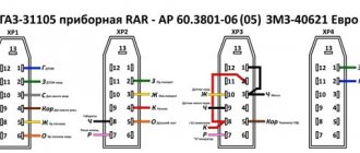
| №1 | Empty |
| №2 | Empty |
| №3 | Empty |
| №4 | Constant power |
| №5 | Antenna power |
| №6 | Backlight |
| №7 | Ignition |
| №8 | Weight |
And Japanese, American and a number of Chinese car brands use the 2DIN standard.
Pinout diagrams for ISO connectors for Pioneer radios
The model name of the Pioneer car radio, the connection diagrams of which are shown above, can be found out from the file name of each diagram.
Remember: when you connect the device for the first time, you first need to supply power to the radio, and if it lights up and switches as expected, connect the speakers. Otherwise, you can burn not only your audio player, but also your expensive car speakers.
To begin with, it is worth noting that incorrectly connecting the car radio can lead to low-quality sound of low power or damage to the speaker system. If such a warning does not scare you and you have a great desire to do everything yourself, then let’s try to figure out this issue together and understand how to properly install the car radio. To complete the job you will need electrical tape, a tester and a screwdriver. The entire installation process can take from 5 minutes to several hours. The following recommendations are applicable in 85% of cases of radio assembly.
Standard ISO connector for modern radios
The car has several configuration options with special connectors and conductors for installing an audio system:
- The conductors in the car are routed to the rear and front speakers, while the power wires come from the battery, and the positive cable is equipped with a separate fuse. The wires are connected to a special connector, which is identical to the socket in the radio. The cord from the antenna is also brought out and fits to the installed audio system.
- All the necessary wires for installation are supplied and connected to the connector, however, the plug does not fit into the car radio socket.
- There are no speaker wires in the vehicle, and the power wires are not routed out. Also, the wires may be present, but not connected correctly.
We will not dwell on the first option in detail, since everything is clear here and you only need to connect the existing power wires and insert the connector. In any case, it is necessary to check whether everything is ready for the new audio system and make sure that the wiring and speakers correspond to the output power of the radio.
Consider in detail the second option, when the car wiring connector does not match the audio system socket. The problem is that almost every company installs individual types of connection connectors on its radios. Different models from the same manufacturer may have completely different outputs. In this case, most often the car radio is supplied with a separate adapter for the ISO standard.
Before performing any actions to resolve the problem, you must finally make sure that the adapter is not included in the kit or that it does not fit. There are two ways to get out of this difficult situation:
To prevent confusion, connect the connector to the radio and bite off the remaining part. The connection of the audio system and car wires is carried out in accordance with the color marking. It is best to solder the connections and then insulate them using heat-shrinkable cambric.
In the case where the colors of the wires are different and do not match, they will need to be tested, and, most likely, the missing wires will need to be routed. To perform this action, you should arm yourself with a tester or a special multimeter with a beeper and a separate 9-volt battery.
Attention!
Any manipulations with the wiring are carried out only with the battery disconnected!
We will not dwell in detail on the process of dialing with a multimeter. Let's look at why a battery is needed and how it is used.
If you ring the speakers and do not disconnect the wires from them, two wires should ring. This will be a pair for a specific speaker. It is to determine their polarity that you need a battery. It is connected to a pair of wires, and then you need to monitor the movement of the speaker cone.
If the diffuser moves outward, then the polarity is selected correctly. The wire that was connected to the plus of the battery is marked as “+”, and to the minus – “-”. If the diffuser retracts, it means that the polarity is chosen incorrectly and the wires must be marked in reverse. The battery is connected to the speaker for just one second.
Pinout diagrams for radio tape recorders from popular manufacturers
Wiring of linear outputs on a standard radio can be done using two RCA connectors. This option is the most common, since power amplifiers have the same sockets. The pinout of connectors for Pioneer car radios contains from 10 to 20 contacts. Their purpose depends on the model of the multimedia device. For example, in the KEH series, the first pin is the antenna control, the second pin is the voltage from the ignition switch, etc. The speakers are connected to pins 3, 4, 5, 6, 8, 9, 10 and 11.
Marking and color coding of wires
Installing a car radio with your own hands will require knowledge of wire markings:
- Black (indicated by GROUND or GND). Minus battery;
- Red (ACC or A+ marking). Plus ignition switch;
- Yellow (designated BAT or B+). Plus from the battery;
- White with stripe (marked FL-). Minus front left speaker;
- White without stripe (designated FL+). Plus front left speaker;
- Gray with stripe (marked FR-). Minus right front speaker;
- Gray without stripe (designated FR+). Plus the right front speaker;
- Green with stripe (marked RL-). Minus left rear speaker;
- Green without stripe (designation RL+). Plus left rear speaker;
- Purple with stripe (marked RR-). Minus right rear speaker;
- Purple without stripe (designation RR+). Plus the right rear speaker.
In addition to the main wires, the audio system may have additional ones, say blue with or without a white stripe, which is intended for connecting an antenna, orange for turning on the backlight, and others.
Standard pinout of the Prology car radio ISO connector
- Purple wire - increases the sound of the right rear speaker.
- Purple, black - decrease the level of the right rear speaker.
- Gray wire - increase the volume of the left rear speaker.
- Gray, black - decrease the sound on the rear left speaker.
- White wire – increases the sound of the left speaker (front).
- White, black – sound on the same speaker.
- Green wire - increases the sound of the right front speaker.
- Green, black - reduce the volume of the left front speaker.
- The yellow wire is powered from the car battery.
- Orange—backlit control keys.
- Blue and white - antenna power.
- The red wire is the ignition switch.
- Black wire - minus (ground).
Connections for some car models and receivers may vary slightly. To what extent these differences are fundamental and can affect the connection of sound-reproducing equipment, you can judge after reading the description of the pinout using the example of a car radio from the Pioneer brand.
Pioneer radio ISO connector pinout
When buying a used car, many drivers want to replace the standard radio (Prolozhi) with a device of a higher level (Pioneer). And they are faced with such a problem as mixed up wiring on homemade twists or with connectors that are not suitable for the Pioneer.
The way out of this situation is quite simple (at least in words). To do this, you just need to purchase an ISO standard connecting device and pin it out according to our recommendations. Due to the fact that all modern car radios have standard ISO connections and rectangular plug boxes on the rear panel, there should be no problems with the connection after pinout.
So, the pinout of the ISO connector of the car radio through 2 Pioneer blocks is done in this way:
- Block with upper contacts, letter B.
- Increase (decrease) the sound reproduction level. The color of the electrical wire is any.
- The wire that mutes the sound, for example, when there is an incoming phone call, etc., is also a free color.
- ACC mode (connected to the car ignition, + appears when you turn the key and disappears when turned off), yellow color.
- Twelve-volt power supply for the radio antenna - blue wire.
- The orange wire is responsible for illuminating the display of the car player.
- Car ignition - red wire.
- Ground – wire with black insulation.
- Bottom junction box - A.
- + right rear speaker of the multimedia system - purple wire.
- Minus - black, purple wire for the left speaker.
- Front right speaker, volume increase—gray wire.
- Right front column. Reduction - black, gray wire.
- The left column (front), plus - the wire color is white, negative - black and white wires.
- Both speakers located at the back (increase, decrease volume), green and a combination of black and green.
Since 2000, some manufacturers of European passenger cars (BMW, Ford, Mercedes, Peugeot, etc.) began to use a 40-pin Euro connector called Quadlock or Fakra. At the same time, the pinout according to wire colors remained the same for the main (named) functions.
How to connect a car radio
Consider in detail the option when installing and connecting the audio system needs to be done from scratch. At the first stage, you need to buy a complete set of wires to connect speakers and power. The length of the wires depends on the characteristics of the vehicle and the chosen installation method. It is best when they are as short as possible and do not have additional twists. A good solution would be to purchase stranded copper wires with silicone insulation. Their thickness should be sufficient to ensure the most efficient operation of the audio system. Power wires with a cross-section of 4 mm. sq. Suitable for car radios with power up to 120 W. In this case, the wires to the speakers have a cross-section of 1-2 mm. sq. quite enough.
The positive power wire must have a thickness of at least 4 sq. mm. and be equipped with a fuse
Often, the same set of speakers contains connecting wires that do not meet the required thickness.
Connecting speakers
Modern audio systems are most often designed to serve 4 speakers. These are two rear speakers and two front ones. Radio tape recorders that produce a power of 30 W or more per channel have four pairs of wires. Each pair has its own color marking. Also in each bundle there is a wire without a stripe (plus) and with a stripe (minus).
You should not confuse the polarity, although this is not so bad. It is strictly forbidden to ground the wire with the strip (minus) that comes from the radio to ground, since it has absolutely nothing to do with the total mass of the car. The speakers themselves are equipped with two terminals (one narrow, the other wide). Low power radios may only have one positive wire per speaker. In such a situation, the minus of the speakers must be connected to the common minus of the audio system. The positive wire coming from the car radio is attached to the wide terminal, and the negative wire to the narrow terminal.
When connecting speakers, pay attention to the polarity, this will allow you to achieve better sound.
Correct phasing should be given special attention. If the pluses and minuses are connected correctly, then you can expect that no problems will arise and the audio system will work properly. In this case, a situation may arise when the sound quality does not meet the required expectations. There is sound, the volume is excellent, however, the low frequencies are practically not felt, and increasing the bass does not change anything at all.
The described circumstances are a sign of incorrect phasing. It will be necessary to check the connecting wires very carefully and reconnect them in those places where necessary.
There is another simpler way to track the correct phasing:
- The sound needs to be transferred completely to the front speakers, and then set the balance to one speaker, for example, to the right. The volume must be increased to maximum levels or until noticeable distortion appears.
- Next, the balance should be moved to the middle position, thereby distributing the volume evenly between the left and right speakers. If phasing is done correctly, the overall volume will increase significantly. A slight increase in volume, no increase in volume, or complete disappearance of low frequencies indicates incorrect phasing. Then you need to swap the wires on one speaker. The same procedure should be repeated on the rear row of speakers.
Almost all modern car radios use three wires of yellow, red and black to supply power. The battery negative corresponds to the black wire. Yellow is a plus of the battery and powers power consumers. If for certain reasons the yellow wire has deteriorated, it is necessary to completely replace it with a new one of the appropriate cross-section. The red wire is the positive wire for the ignition switch.
Detailed car radio connection diagram
First you need to figure out how to connect the black and yellow wires. Many motorists connect the black wire to the first free ground bolt, and the yellow wire is connected from the ignition switch or cigarette lighter. In fact, this method is wrong.
By connecting these wires to the battery you can get high-quality, high-power sound. It is best to take multi-core copper wires with a thickness of 4 square meters or more. mm. Having retreated 30-40 cm, a 10-20 A fuse with good insulation is installed on the yellow wire. The red wire also has a positive value, however, it must be connected to the ignition switch. And to be very precise, it connects to the circuit that is energized in the ACC key position.
It happens that car enthusiasts connect the yellow and red wires together. The advantage of such actions is that the audio system is constantly working and does not depend on turning the ignition on or off. Of course, the downside in this case is that the radio is in standby mode all the time. This will affect battery performance. The battery drain rate will increase. This indicator depends on each individual radio, so it is quite problematic to specifically calculate how quickly the battery will drain.
Power connection
Connecting the power supply is the stage at which most mistakes are made when connecting the radio.
To connect power to the radio, it is better to use a separate wiring to the battery, and the wires should have a cross-section of 2-4 sq. mm.
To obtain clean playback after installation, it is better to connect the black and yellow wires to the battery. Install an additional 10-20 A fuse on the yellow wire. The red wire is connected to the ignition circuit.
As a rule, the red and yellow wires are connected together, so the radio operates regardless of the ignition being turned off. But this option has a caveat - the radio will drain the battery, because will remain in sleep mode all the time after shutdown. To eliminate the possibility of the battery being discharged due to this nuance, a separate shutdown button is additionally placed on the red wire, thanks to which the power will turn off automatically when the car is parked for a long time.
Most people want to replace their stationary radio with a built-in one. This decision may be prompted by the fact that factory radios do not always produce the required number of watts or provide little power for the installed speakers.
Read more: Pinout of the towbar socket, types of connectors and diagram of connecting the trailer electrical to the car
The main rule when replacing stationary radios with built-in ones is the correct selection of adapters and related connectors.
Thus, the KY83190A radio, which is installed on Lifan cars, has its own plugs and is built into the standard 2Din slot already provided by the manufacturer. To use the KY83190A radio on other cars, special adapters for ISO standard plugs are required.
Let's consider options for connecting built-in radios from Sony, Pioneer or JVC.
The manufacturer of the JVC brand radio has already made sure that the buyer, when purchasing his car radio, can install it himself. It comes with special studs for fixing the back and front for easy installation. JVC models are connected via an ISO connector.
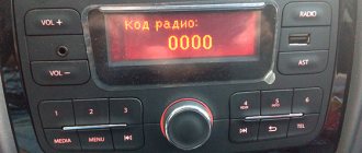
For high-quality music sound, you need to move the fuse on the end side of the radio to the next socket, and connect the gearbox wire to the battery and insulate the reinforced concrete wire. It is also better to give preference to higher quality wires. Let's take a SONY brand radio as an example; most of them are also connected according to the standard scheme via an ISO connector, but it happens that some models have ISO connectors. They are individual, and you need to choose ISO adapters for them, or cut the wires and connect them to the connectors according to the diagram.
Of course, it is not recommended to cut the wires for connection, but if this happens, it is better to use heat-shrinkable tubes rather than electrical tape, since in winter it peels off, which can lead to a short circuit. In any case, connecting the car radio will become more convenient if it already has an ISO connector.
As for the Pioneer car radio, it also has ISO connection connectors. The connector for connecting the Pioneer radio has two plugs: black (from which the radio is powered) and brown (which produces acoustic output to the radio). When installing the Pioneer radio, you must correctly connect the red positive wire and use the battery fuse.
Thus, connecting the ISO connector of the radio greatly simplifies the work process.
Antenna connection
External view of an active interior car antenna
The antenna comes in passive and active types. Connecting a passive antenna is very simple. To do this, you just need to insert the plug into the appropriate socket. But installing an active antenna requires a little work, since power needs to be supplied to it. Most modern car radios have a special output. It is a blue wire with or without a white stripe and is labeled REM, ANT, or AMP. Sometimes there are two such wires. They are responsible for turning on devices that operate only when the audio system is being used. In our example, it is the antenna that is such a device.
The raised question of how to connect a radio and the direction of car audio is not just the topic of a separate article. In fact, this is a whole science, for the study of which there is a huge amount of manuals, information and books. In this article, we tried to dwell only on the most important aspects and details of installing an audio system.
Car radio ISO connector pinout: all about Euro connectors or Euro chips
Recently, more and more of our compatriots are paying attention to the arrangement of speaker systems in their cars. Today, there are many solutions to ensure high-quality sound from car radios. From this material you can find out what the ISO connector of the radio is and what its pinout is.