Reasons for their natural and premature wear
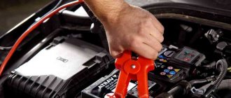
The spark plug operates under extremely extreme conditions:
- high temperature in the working cylinder;
- aggressive environment in the form of a mixture of fuel, air and oil;
- high pressure during ignition;
- high voltage and temperature of electric spark.
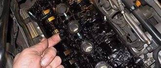
The simultaneous action of these factors leads to an intensification of the processes of their natural wear. This process can be significantly accelerated in the following cases:
- reduction of compression, wear of valve stem seals due to oil entering the working volume;
- incorrect setting of the ignition angle, leading to the formation of increased carbon deposits;
- choosing spark plugs that do not match the engine brand;
- misfire in cylinders;
- incorrect gasoline/air ratio due to malfunctions of the flow meter, air leaks;
- incorrect operation of injectors.
How does a microprocessor ignition system work?
About the design and operation of the car What is 4wd.
FWD drive - what is it? The main components of the all-wheel drive system. A pleasant discovery was the fact that it is quite possible to assemble a new microprocessor system circuit with your own hands according to the MPSZ scheme from ready-made components. And of course, to configure the microprocessor unit you need a computer, a COM-COM or COM-USB cord and a couple of service programs, including a firmware option for the table of advance angles of the ignition initiation moment.
For your information!
This is the most important stage and you won’t be able to get away with using a standard tabular set of values. For example, MPSZ firmware for UZAM engines is very different from VAZ, especially GAZ.
Unlike older versions, in which the moment of formation of the high-voltage spark plug pulse was determined by the ignition distributor, in the new microprocessor circuit the command is sent to the coil based on processing information from several sensors:
- crankshaft position, it is often necessary to purchase a new cover with a boss for the sensor, and when installing it requires a little fiddling due to the small space for work;
- the absolute pressure sensor provides the microprocessor unit with the degree of vacuum in the intake manifold, which allows the electronics to indirectly make corrections for the degree of engine load;
- coolant temperature sensor;
- the knock sensor is mounted according to the instructions on the middle part of the block under a special bolt with a nut;
- synchronization sensor.
In addition to the sensors, you will need a microprocessor switch unit itself, a new ignition coil with two contacts and a wiring harness with chips.
The possibility of purchasing the assembly in parts provides savings, but does not guarantee stable operation
Design and principle of operation
The first switches were extremely primitive. A simple circuit of transistors was regulated using an electrical impulse. The device did not last long in this form. The era of high technology has arrived, thanks to which more effective innovative solutions have begun to be applied.
On cars assembled in the Russian Federation, the spark stimulator was first used on the VAZ-2108 car. The device belonged to the 36.3734 series, also of native production. Subsequently, more modernized switches with different design and technical designs began to be used. However, combined or composite assembly technology has always remained unchanged for Russian microcircuits. And its advantage is that it is repairable, unlike the same foreign analogues.
Today, a switch is a combination of several elements: spark plugs, transistors, sensors. It can be used in hybrid or thyristor ignition. Electrical impulses are controlled automatically, which provides a number of practical advantages:
- no interruptions at maximum speeds;
- increasing the reliability of the unit;
- possibility of increasing the engine cylinder capacity.
And when the Hall element was introduced, and the switch began to control several converters at once, the advantages only increased. So much so that they began to use a “coil + commutator” tandem on each individual spark plug. Here's what exactly we managed to achieve:
- the spark in the ignition system has become stronger and more reliable;
- power losses in the distributor have disappeared;
- improved idle speed;
- fuel consumption has decreased;
- Starting on a cold engine has stabilized.
The principle of operation of the switch can be imagined as follows. First, the system monitors the position of the engine crankshaft. Then, an inductive Hall sensor included in the distributor design takes readings from the position of the pistons in the cylinders. It also supplies the switch with an impulse. The signal is amplified to 12 volts and sent to a coil. Due to this, the current decreases and the voltage increases.
Nowadays, electronic switches are used for efficient ignition of fuel in VAZ 2109, 2110, 2114 Samara, as well as ZAZ-1102. The 3734 series of these devices is produced under article numbers 3620-, 36- and 78. The tasks of the key here are performed by a productive mosfit, and the current value is controlled by an integrated electrical circuit.
Windshield washer pump does not work
IntroductionPurpose, design, principle of operation of the brake system of the VAZ 2112
The washer pump, as a rule, is made in a single housing with an electric motor and is installed in the fluid reservoir, so its operation is accompanied by a characteristic buzzing sound audible from the cabin. Turn on the ignition without starting the engine and press the steering column switch lever. If “there is silence in response,” it means the windshield washer motor did not turn on.
Troubleshooting sequence:
- checking (replacing) the windshield washer pump fuse
- checking the voltage supply fuse with a probe
- relay check. If it is working properly, you will hear a slight click when it operates.
- checking the voltage supply to the relay
- relay replacement
- “continuity” of wiring from the steering column switch
- checking the voltage supply to the pump
- search for broken wiring
- pump replacement
How to remove the windshield washer pump
Let's look at how to remove the windshield washer pump. First of all, you need to provide access to it. On domestic cars, the reservoir with a pump is installed in the engine compartment. Owners of foreign cars have to remove the fender liner, at least partially, in order to get to it. But there are also cars in which the engine is accessible only when the front bumper is removed. On some cars, it is enough to remove the plastic boot between the bumper and the fender liner. Sometimes a removable hatch is provided in the fender liner, which greatly simplifies repairs.
The pump is inserted into the tank with a suction fitting through a rubber seal. If you have checked the power supply to the electric motor, remove the pump.
Just make sure you are not removing the rear window washer motor. The headlight washer features noticeably larger diameter hoses with quick-release fittings.
If the motor does not show signs of life, change it, since repairing it is a thankless task, unless you have Left-handed abilities.
What can be put on the classics from the existing MPSZ
Coursework Vehicle Safety
Among the most well-known microprocessor systems, Maya, Secu 3 or Mikas MPSZ are most often used. Assembling any of them is not difficult, if you have the skills to correctly see and read the instructions with the diagram, and follow the sequence of installation actions.
When choosing a microprocessor system, you should not be intimidated by the fancy circuitry that product sellers like to show off, offering the services of a familiar electrician for “guaranteed high-quality installation for pennies.” All components can be installed on the classic with your own hands.
When choosing, pay attention to the quality of the block itself. It is considered good form if there is no warping of the plastic parts, burrs or microcracks
The second indicator is the presence of a large scattering surface in the form of an aluminum base. The microprocessor remains the most capricious part and the choice of place under the hood or in the cabin must be taken very seriously.
The ignition coils can be separated into a separate unit; alternatively, they can be mounted directly next to the spark plugs on the head cover.
Classics need microprocessor bells and whistles
First, incomplete analogues of the microprocessor ignition system for the classics appeared, in which the distributor was converted to work with a Hall sensor and the control system was modified. But smart car enthusiasts know that in the microprocessor ignition system for carburetor engines, the distributor or distributor in Russian remained the problematic link.
Moreover, the good idea of electronic ignition has a fundamental drawback - the characteristics of the ignition timing for a cold engine and a warm one are fundamentally different. When adjusting the advance angles on the distributor for a cold engine, detonation will certainly appear after it warms up.
Therefore, the developers of microprocessor units for the classics had to go further and modify it, turning the ignition system for the classics into almost a complete analogue of the injection version, with the exception of the control of the injection system.
Advice! To what extent the new microprocessor ignition system is adapted to the realities of working on a classic, ask the owners of the “miracle electronics” who have been away for at least a season.
What does such a microprocessor ignition system provide:
- the absence of an ignition distributor in the circuit has a beneficial effect on spark stability and the absence of “contact bounce”;
- idle stability is practically not inferior to an injection engine;
- The main advantage of the microprocessor system is the “smart” selection of the ignition timing according to the engine parameters, which allows you to work at optimal angles and not get into the detonation zone.
- Fuel economy on a regular, unkilled Zhiguli “six” engine per lap is reduced on average from 10 liters of gasoline to 6-7.
For your information! A miraculous reduction in gasoline consumption is only possible with an absolutely serviceable and adjusted carburetor, otherwise the electronics will only worsen the consumption situation.
Do-it-yourself troubleshooting and repairs
Malfunctions are simple if they do not require disassembling the chainsaw to eliminate them. For Husqvarna 142, the methods for finding them, as well as eliminating them, are no different: it all comes down to checking the condition of the spark plug, the fuel level in the tank, etc.
If easily correctable malfunctions occur, it is necessary to remove individual components, replace or repair them, and then reassemble the Husqvarna chainsaw
142. This is how shock absorbers or carburetors are replaced and the starter is repaired. To repair the starter, it is better to first familiarize yourself with its structure, for example, from a video.
If the chain is not lubricated, we recommend watching a video that discusses in detail the lubrication system, its disassembly and assembly
.
If complex faults occur, complete disassembly is necessary. The design of the Husqvarna 142 chainsaw is not complicated, but you must be absolutely sure that for high-quality repairs you can:
- receive drawings of the device with a description and you can do the detailing;
- perform troubleshooting and reassembly.
Is it worth it to repair the Husqvarna 142 piston group yourself? For high-quality overhauls, you must have at least precise tools - a micrometer and a bore gauge - which can cost you more than spare parts. If you decide to do a major overhaul, we recommend watching a video that sequentially shows how to disassemble the Husqvarna 142, and our article on repairing Husqvarna chainsaws.
Diagnosis of ignition distributor faults
Small faults can occur inside the distributor, which can reduce engine power and efficiency. The most common cause of malfunctions, which, however, is not paid attention to, is unstable ignition timing due to wear of the distributor shaft bearings. In a distributor with a contact breaker, excessive bearing clearance can cause the breaker cam to oscillate, causing an uneven spark and changes in the contact angle. This not only changes the ignition timing, but also seriously changes the intensity of the spark at high engine speeds and often leads to misfire.
Most distributors use bronze bushings, and wear can be a problem when they receive insufficient lubrication, or if heavily spring contacts are used, as the friction block(s) are subject to significant lateral loads from the distributor shaft. It's easy to check the bearings for excessive wear: remove the distributor cap and rotor, grab the shaft tightly and try to rock it back and forth. Apply force in different directions as the bushings may wear unevenly. If there is noticeable displacement, the bushings should be replaced. For optimal operation in a distributor with a contact breaker, the gap between the shaft and the bearing should be no more than 0.05 mm. The bearing clearance is not so critical in a non-contact distributor, since small changes in the distance between the protruding rotor and the sensor do not have a strong effect. However, even in such distributors the gap should not exceed 0.13 mm.
Centrifugal and vacuum ignition timing regulators in the distributor play an important role in optimizing engine performance and efficiency. Like all mechanical systems, these components are subject to wear and component failure and must be carefully inspected.
The vacuum regulator can be easily tested by simply applying air to the diaphragm using a hand vacuum pump. In this case, you need to look inside the distributor to check whether the breaker plate rotates when the vacuum level reaches approximately 175 mmHg. Art. Continue increasing the vacuum to 250 mmHg. Art. or more and make sure there are no vacuum leaks within a few seconds. If even a small vacuum leak is detected, check that the leak is in the vacuum chamber and not in the hand vacuum pump by pinching the rubber vacuum hose and observing the breaker plate. If it returns to its previous position, then the camera needs to be replaced.
A centrifugal governor is usually one of two types. One design used on many General Motors vehicles is
Distributor diagnostics
Many older vehicle ignition systems had a distributor installed, and it was often the cause of engine malfunctions. In contact breakers-distributors, the elements of the contact group often burn out, and for this reason the motor may be difficult to start or may not start at all. In non-contact distributors, the Hall sensor may fail, but this is not a typical “disease” of distributors - sensors do not break so often.
The most common distributor malfunctions:
- burnout of the resistor on the slider;
- the appearance of cracks and burnout in the distributor cover;
- breakage of the Hall sensor wiring (this is often noted in VAZ 2108-09, GAZ 31029-3110 distributors with a ZMZ 402 engine);
- wear of the shaft bearings.
The distributor cap on Russian cars is very inexpensive, can be changed within a few minutes, and therefore it is better to always have such a part in stock. The easiest way to check the cover is to replace it - if the motor starts working properly, it’s all about it.
b REUMKHVEYAYNE NAYAKSFKHBYUMKHE YAHYARELSH GUFKHTSYUMKH BUNDIR OPNBEPIYU SYARYUMNBYKH LNLEMRYU GYUFKHTSUMKH, NVH ...
b REUMKHVEYAYNE NAYAKSFKHBYUMKHE YAHYARELSH G ...REUMKHVEYAYNE NAYAKSFKHBUMKHE
| REUMKHVEYAYNE NAYAKSFKHBYUMKHE YAKHYARELSH GUFKHTSYUMKH b REUMKHVEYAYNE NAYAKSFKHBYUMKHE YAKHYARELSH GYUFKHTSUMKH BUNDYR OPNBEPIYU SYARYUMNBYKH LNLEMRYU GUFKHTSYUMKH, NVHYARYU YABEVEY G YUFKHTSYUMKH NR MUTSYUPYU X HU GYULEMYU, OPNBEPIYU YPEOKEMKH X KGNKIZHKH OPNBNDNB. oPH REUMHVEYAYNL NAYAKSFKHBYUMKHH AEYAYNMRYURMNI YAKHYARELSH GUFKHTSYUMKH MENAUNDHLN OPNBEPHRE VHYARNRS X YPEOKEMHE BYAU OPKHANPNB X OPNBNDMHYNB. mYUPSFMSCH X BMSRPPEMMCHCH ONBEPUMNYARKH YPSHYYH DYURVKHYU-PYYAOPEDEKHREK X PNRNPYU MSFMN RYYUREKEMN OPNRKHPYURE VHYARNI RPONVYNI, YALNVEMNI AEMGKHMNL, GYUVKHYURE SHKEYRPND SH ANYNBSHU YKELL X RNYNPYUSCHMNNYAMSC OKYUARHMS PNRNPYU. MUDN RUYFE OPNRKHPURE YNPOSYA SHKEIRPNMMNTSN YNLLSRYURNPYU KH YURSYS GUFKHTSUMKH, OPNBEPRER MUDEFMNYARE YPEOKEMKH YANEDHMEMKHI B SHCHKEIRPHVEYAYKHU JEOYU MHGY NTsN X BSHYANYNTSN MUOPFEEMKH I ZHEKNYARMNYARE GYUYKHRMSHU YNKOYUVINB BYAU YANEDHMEMKHI. yPNLE SCHRNTSN, MENAUNDHLN OPNBEPRRE OKNRMNYARE ONYYUDYKH OPNBNDNB MU ONKMSCH TsKSAHMS MU MYUNMEVMHYUU YABEVEI KH B YPSHYE DYURVKHYU-PYUYAOPEDEKHREK. YaBEVKH B AEYAYNMRYURMNI YAHYARELE GUFKHTSUMKH GYULEMCHR VEPEG YUFDSHE 17≈20 RSHYAV YL OPNAETSIU. vRNASH GYUOSYAY DBKHTSYUREK I AEYAYNMRYURMNI YAKHYARELNI GUFKHTSYUMKH B GKHLMKHI OEPKHND ASHK MYUDEFEM, GHLNI YABEVKH GYUFKHTSUMKH MEGEYUBKHYAHLN NR KH YANYARNYMKH PAINLEMDSERYA G YULEMERE MNBSHHLH, YU YAMERSHE YABEVKH HYAONKEGNBURE BEYAMNI X KERNL. eYAKKH KGNKЪRNP YABEVKH GUFKHTSUMKH KHLEER ZHBER NR YABERKN-YAEPNTsN DN YABERKN-YNPKHVMEBNTSN, YNPOSYA VKHYARSHI, SHKEYRPNDSH ME KHGMNYEMSH, RN SCHRN TsNBNPHR N YANNRBERYARBKH YABEVKH DYUMMNLS DBHTSUREKCH H EE MNPLYUKEMNI PUANRE. VEPMSHY YASUNI MUTSYUP MU YABEVE NGMYUVYUER, VRN NMYU ME YANNRBERYARBSER DUMMNLS DBHTSUREKCH KHAN PYUANVYU YALEYAE OEPE-NANCYUYU. bSHTSNPEBKHE SHKEYRPNDSH SYUGSHBUCHR MU OEPETSPEB YABEVH, BSGBYUMMSHI EE MEYANNRBERYARBHEL DUMMNLLS DBKHTSUREKCH, MU OPHLEMEMKHE MHGYNNNYRYUMNBNTSN AEMGHMYU X MU MEOPYUBHKE MSCH SYARYUMNBYS GUFKHTSYUMKH. b NREVEYARBEMMSHU YUBRNLNAKHKU YARYUPSHU LYUPNY SYARYUMNBYS LNLEMRYU GYUFKHTSUMKH OPNBECHR ONYAKE OEPBSHU 2000 YL OPNAETSU X GYUREL ONYAKE YUFDSHU 10 RSHYAV YL OPNA ECJ. b YANBPELEMMSHU YUBRNLNAKHKU GYUPSAEFMNTSN OPNKHGBNDYARBU LNLEMR GYUFKHTSYUMKH RNKEIN SYARYUMYUBKHBUCHR X HE OPNBEPR. VEPEG YUFDSHE 10 RSHYa'V YL OPNAETSIU YABEVH GUFKHTSYUMKH MENAUNDHLN NVKHYYURE NR MUTSYUPYU, YU VEPEG YUFDSHE 30 RSHYA'V YL OPNAETSYU GYULEM'RE HU MNBSHLH. |
| YALNRPKHRE RUYFE: b OPNZHEAYAYE SHYAOXYURYUZHHH YABNIYARBU YUBRNLNAKHK ONYARNMMN LEMCHRYA. ShRN OPNЪBKЪRYAЪ B YAMKHFEMXX MYUDEFMNYARKH, DKHMYULKHVEYAYKHU YUVEYARB |
| REUMKHVEYAYKHI NYALNRP YUBRNLNAKHK OPEDYARYUBKER YANANI YNLOKEYA YNMRPNKEMSHU NOEPYUZHKHI, YNRNPSHE OPNBNDRYA OEPED MYUVYUKNL SCHYAOKSURYUZHHH... |
| b NAZEL X YUYUPYUREPHYARKHYH PUANR, BSHONKMYELSHU YUBRNYAKEYUPEL (B GYUBHYAHLNYARH NR ETSN YBYUKHTHYUZHHH) OPH REUMHVEYAYNL NAYAKSPHBYUMHH X P ... |
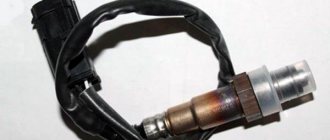
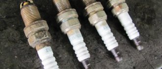
Signs that they need to be replaced
The main sign of the need to replace spark plugs is misfires (tribling). This is not always due to problems with spark plugs. To finally decide on the need to replace them, the easiest way is to install a known good one instead of the problematic spark plug.
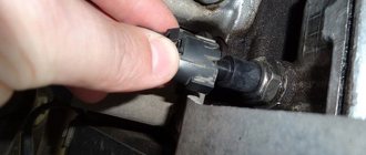
The easiest way to identify a possibly faulty spark plug is with the engine running. To do this, it is necessary to sequentially disconnect the high-voltage wires (or the connector of the individual ignition coil) from each of them. The non-working cylinder will be the one from which, when disconnected, the nature of the engine operation does not change.
Also signs of a required replacement of spark plugs are:
- visual malfunction (contamination, carbon deposits in the gap area, change in the normal gray color of carbon deposits, its wetting, mechanical chips on the insulator);
- unstable engine speed;
- increased smokiness of exhaust gases;
- engine detonation;
- message or on-board computer.
Malfunctions of high-voltage wires
I/O wires lose their insulating properties over time, and the conductive element inside the wires may also break. But most often the wires begin to break through to ground - the insulation cannot withstand the high voltage. It is good to diagnose high-voltage wires in the dark - when it is dark, you can clearly see where the spark breaks out. If there is a breakdown of the spark, the engine troits and does not develop the required speed.
In non-contact ignition systems with a distributor, a switch is installed; it is designed to ensure uninterrupted sparking at the spark plugs, and also serves to form a stable spark at all engine speeds, including idle. If the switched device fails, the engine begins to start poorly, and in many cases does not start at all.
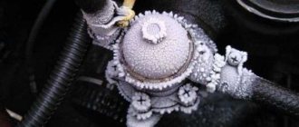
The main sign of a faulty switch is that it is very hot; overheating can be determined by touching the body of the device with your hand. As a rule, along with the commutator, the coil also gets very hot. Often these parts heat up and fail on old Gazelle and Volga GAZ 31029-3110 cars with a ZMZ 402 engine. The reason for such frequent breakdowns is the low quality of spare parts supplied by various manufacturers.
- All about spark plugs types rating rules for selecting faults
- Contact ignition system full description of the operating principle
- Ignition coil breakdown and signs of malfunction
- Manual transmission - device, operation and main malfunctions of manual transmission
Malfunctions in the ignition system
If there is no spark, first of all you need to check:
- on contact systems, the presence of a spark on the contacts;
- on electronic ones - serviceability and presence of a signal from the speed sensor (crankshaft or camshaft sensor);
- the presence of supply voltage at the switch, control unit, and ignition coil(s);
- integrity of high-voltage wires;
- integrity of ceramic parts (distributor cover, “runner”, etc.);
- spark plug;
- serviceability of electronic control units;
In case of misfire, the reasons must be sought, first of all, in the high-voltage system. Voltage leaks in armored wires, spark plugs, and coils.
Also, the high-voltage part can be the cause of “triple” or “tweaking” of the engine, “shooting” at the air filter or muffler (especially cars with gas equipment), poor starting, both cold and hot.
The most optimal way to diagnose various ignition systems is to take oscillograms from the primary and secondary sparking circuits. The oscillogram can be used to determine almost all types of ignition system malfunctions, such as:
- breakdown of armored wire;
- interturn closure of the coil;
- absence or distorted signal from sensors and switch;
- spark plug defect;
Unfortunately, without an oscilloscope, the fault can only be eliminated by replacing parts with known good ones.
There are, of course, other “folk” methods, they are certainly not effective enough, but with their help you can determine which part should start replacing, for example:
- In the dark, open the hood with the car running; if the effect of the “northern lights” is visible, that is, the glow of the “armored wires”, they need to be replaced.
- Visual inspection of spark plugs for ferritization of the electrode insulator (the appearance of a red conductive coating on the spark plug insulator, due to low-quality fuel with a high content of metals and ferrocene) and the appearance of breakdowns in the form of current paths.
- Inspect the distributor and ignition distributor caps for cracks and breakdowns.
Advice
Never test for spark in electronic ignition systems by removing the high voltage wire from the spark plug. With a high degree of probability, the coil itself, the electronic control unit or the switch will fail.
On contact ignition systems, it is allowed to clean the contacts with a file or nail file, followed by restoration of the gap.
Symptoms of a Switch Problem
Loss of spark by the ignition system is one of the main symptoms of a lack of serviceability of the switch. Naturally, this is accompanied by difficulty starting the engine and interruptions in its operation. However, experts warn that there is no need to rush to replace the element, because similar symptoms are also present in other problems. For example, this also happens when the timing belt breaks, the distributor or ignition coil is damaged, the wiring connections are weak, etc.
In a word, you need to check the switch correctly. But how can you do this without qualifications, because the device has a complex design. There are several practical ways. The first is not to bother and install a new switch. If the problem goes away, then everything is fine. The second method involves using a 12-volt test lamp and a standard set of keys.
Following are the instructions:
- de-energize the battery;
- remove the control wire “K” from the ignition coil - it is often painted brown or red and routed to the main terminal of the switch;
- In its place, install one end of the control lamp, connect the other to wire “K”;
- connect external power supply 12 volts - battery;
- start the engine.
If the lamp starts blinking, the switch is working. The opposite situation, when the indicator does not show any operating signs, will indicate problems with the device. It is unlikely that it has completely deteriorated, then the engine would not start the first time.
Signs of a switch malfunction can be more accurately seen on professional equipment - a special stand. This makes it possible not only to determine whether the device is working, but also to calculate the duration of the pulses. In addition, specialists separately measure the voltage at the output of the Hall sensor - the norm is no more than 0.4 V. The first and second terminals of the switch are also closed when the ignition is on to test for the presence of a spark.
The better the distributor
To understand why MPS is better than a distributor (distributor), I will give several examples of the negative operation of the last element. First, the car system is unstable due to poor performance of the distributor itself. Second, the distributor system consists of moving parts. Moving elements sometimes fail, and this affects the entire operation of the vehicle system. Often the causes of breakdown of the moving elements and contacts of the distributor are electrical erosion and combustion. This reduces its reliability and productivity. Third, the distributor’s inherent inability to respond correctly to the ignition timing relative to the engine speed of the car.
As for the MPSZ, this system is not only capable of receiving and processing data on the ignition timing, but also making optimal adjustments. To make adjustments, the system needs to obtain readings of two parameters: the temperature of the OPS and the knock sensor. The distributor is unable to perceive such indicators. In addition to this quality, the microprocessor unit eliminates and prevents many other shortcomings of the distributor, including those mentioned above.
If you decide to install MPSZ on your car, then you automatically have a number of advantages. These are: reducing fuel consumption, improving and increasing the dynamic performance of the car, creating smooth transitions from one gear to another, while the power remains the same at low engine speeds. So I wish you success in installation and operation.
Ignition switch malfunctions
In non-contact ignition systems with a distributor, a switch is installed; it is designed to ensure uninterrupted sparking at the spark plugs, and also serves to form a stable spark at all engine speeds, including idle. If the switched device fails, the engine begins to start poorly, and in many cases does not start at all.
The main sign of a faulty switch is that it is very hot; overheating can be determined by touching the body of the device with your hand. As a rule, along with the commutator, the coil also gets very hot. Often these parts heat up and fail on old Gazelle and Volga GAZ 31029-3110 cars with a ZMZ 402 engine. The reason for such frequent breakdowns is the low quality of spare parts supplied by various manufacturers.
Idle cylinder detection
A simple and proven way to determine a non-functioning cylinder without using a tool is to disconnect the high-voltage wires from the spark plugs one by one while the engine is running. When the high-voltage wire is disconnected from the spark plug on a working cylinder, the sound of the power unit will change and even greater vibration will appear. If you disconnect the high-voltage wire from the spark plug on an inactive cylinder, nothing will change in the operation of the internal combustion engine.
High-voltage wires are high-risk parts due to possible electric shock, so when performing diagnostics using this method, you should take care of your safety and follow the rules
- hands and clothes are dry;
- When disconnecting the wire, hold the cap.
Ignition system malfunctions
Malfunctions of battery ignition devices are detected by external signs, which include interruptions in engine operation, difficulty starting the engine, or “shots” from the muffler.
If interruptions occur in one of the cylinders, then most likely the spark plug or the wire going to it is faulty.
Spark plugs may have the following faults: a crack in the insulator, carbon deposits, oiling and violation of the gap between the electrodes. You can detect a faulty spark plug using a voltoscope. Bright, evenly alternating flashes of gas visible in the voltoscope eye indicate the serviceability of the spark plug; A dim or unevenly alternating gas glow indicates a faulty spark plug. In the absence of a voltoscope, the operation of the spark plugs is checked one by one by disconnecting the high voltage wire. If the disconnected spark plug is working properly, then engine interruptions increase. If you disconnect the faulty spark plug, the interruptions will remain unchanged. The faulty spark plug is removed and inspected. Carbon deposits are removed by cleaning the electrodes at the bottom of the spark plug insulator and rinsing it with gasoline. The best way to remove carbon deposits is to clean them with a special device. The gap between the electrodes is adjusted by bending the side electrode, and the spark plug with a damaged insulator is replaced.
Interruptions in the operation of various engine cylinders can be caused by the following malfunctions of the distributor-distributor: burnt or dirty contacts and violation of the gap between them; by shorting the breaker lever or its wire to ground; cracks in the distributor cap and rotor or poor contact of the central terminal; capacitor malfunction; damage to the insulation of the secondary winding of the ignition coil.
Burnt contacts are cleaned using a contact cleaning plate or a file, and dirty contacts are wiped with ends dipped in gasoline. The gap is adjusted in the manner described earlier. If the breaker lever or its wire is shorted to ground, you need to inspect the wire and lever, wipe them with a rag soaked in gasoline, and if the wire is exposed, insulate it with insulating tape.
If there are cracks in the distributor cap or rotor, they must be replaced. Check the condition of the carbon contact and spring. Replace a broken carbon contact or spring, and clean dirty ones. Capacitor fault detected. due to strong sparking at the contacts of the breaker, as a result they burn out, the engine runs intermittently, and sharp pops appear in the muffler. The capacitor is checked in the following ways. The capacitor wire is disconnected from the clamp and, turning on the ignition, the breaker contacts are opened by hand, and a strong spark appears between them. A slight spark between the contacts when they open after connecting the capacitor wire indicates that the capacitor is working. If the spark between the contacts remains strong even after connecting the capacitor wire, then the capacitor is faulty. A faulty capacitor must be replaced. The capacitor can be checked for a spark; for this, the high voltage wire must be kept at a distance of 5-7 mm from ground. An intense spark between the wire and ground when the contacts open is also a sign that the capacitor is working. The reason for failure of the battery ignition may be a malfunction of the ignition coil, which includes: damage to the insulation of the windings, cracks in the carbolite cover and damage to the additional resistor. Damage to the insulation of the ignition coil windings most often occurs as a result of overheating of the windings. The windings overheat if the ignition is left on for a long time while the engine is not running.
To check the presence of high voltage current, use a voltoscope. If it is not there, then you need to remove the distributor cap and turn on the ignition; set the breaker cam to a position in which the contacts are closed, bring the high voltage wire from the ignition coil closer to ground by 4-5 mm and open the contacts by hand. The appearance of an intense spark between the wire and ground indicates the serviceability of the high voltage circuit. If there is no spark, it is necessary to check the serviceability of the low voltage circuit, for which turn on the lamp in parallel with the open contacts of the breaker. When the ignition is turned on, the lamp should light up.
Ignition coil diagnostics
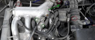
Ignition coils (IC) on cars fail quite often; due to the malfunction of these parts, the engine may not start at all or may stall and not gain speed. It should be immediately noted that short circuits can be different in design - on older models there was one round cylindrical coil, on modern internal combustion engines the following are installed:
- double (two short circuits each) or monolithic modules with high-voltage wires and lugs;
- coils for each cylinder - such ignition modules are installed directly on the spark plugs, and they do not have I/O wires or tips.
Short circuits are checked in various ways:
- external inspection;
- ohmmeter;
- oscilloscope.
Often the coils fail due to overheating, and on older engines (for example, VAZ “Classic”), as a result of a break or short circuit of the winding turns, the engine stops starting, since the short circuit is installed on these engines alone. On newer cars, if the winding is faulty, only one or two cylinders stop working, and the engine starts to misfire.
The coil should be inspected very carefully - there should be no burn marks on its current-insulating parts, and there should also be no cracks. If external defects are detected, the part must be replaced - in any case, it will not last long.
DETAILS: Design and principle of operation of the pump (pump) of the engine cooling system
You can check the integrity of the short-circuit windings using an ohmmeter:
- on the primary winding the device should show within one Ohm;
- on the secondary winding the resistance ranges from 5 to 20 KiloOhms.
Indicators for different KZ models may differ; each brand has its own parameters. But it is not always possible to determine the serviceability of a part by its resistance; this can be more accurately determined using an oscilloscope or by replacing it with a known-good spare part.
Possible malfunctions of the ignition system
Below are the main malfunctions of the contactless ignition system, their causes, and solutions.
1. The engine does not start
Possible symptoms of this malfunction and ways to eliminate them are as follows:
at the 12 V terminal of the additional resistor the voltage is zero. In this case, the ignition switch may be faulty or there may be a break in the wires. The faulty ignition switch must be replaced, the contact in the wires must be restored;
at the ON2 terminal of the additional resistor, the voltage is 12 V ± 10%. This may be caused by a malfunction of the radio interference filter or a break in the wires going from the filter to the additional resistor or from the switch. A faulty radio interference filter or wire needs to be replaced;
at terminal VK12 of the additional resistor the voltage is zero. Cause of the malfunction: failure of the additional resistor. The resistor needs to be replaced;
there is no high voltage at the central terminal of the ignition coil. In this case, the distributor sensor, switch or ignition coil is faulty. This must be determined as described above. A faulty device must be replaced.
2. The engine starts, but runs intermittently
Possible signs and causes of the malfunction: when the engine speed increases, the voltage at the 12 V terminal of the additional resistor or the “+” battery increases to 16 V or more. This is caused
Voltage regulator malfunction. The regulator must be sent for repair;
Interruptions in engine operation are more noticeable at idle than when operating under load.
Cause of malfunction:
dirt or surface breakdown on the distributor cap or slider. The cover or slider should be cleaned or replaced;
interruptions in engine operation are observed immediately after starting and are noticeable in all modes of its operation. This may be caused by a lack of contact at the places where the wires are connected to the ignition system devices. Loose installation of the high-voltage wire tips in the distributor cap and ignition coil; internal breakdown in the ignition coil.
In these cases, you should check and restore contact in all connectors and with the vehicle ground and the installation of high voltage wires. Replace the faulty coil.
interruptions in engine operation are observed after warming up the engine and the switch after 30 ... 60 minutes.
This occurs when contact is broken at the soldering points of radioelements on the switch’s printed circuit board. The switch needs to be repaired.
3. Engine does not develop full power
Signs of this malfunction and their causes: engine starting is difficult due to incorrect setting of the initial ignition timing. It must be installed in accordance with the recommendations given in section. "Engines and their systems";
the engine starts easily. This occurs when the centrifugal ignition timing regulator is not adjusted correctly. The distributor sensor needs to be replaced or repaired.
Designs of ZIL trucks
How to check the switch yourself?
- How to check the switch yourself?
- 1. Signs of a faulty switch
- 2. Algorithm of actions for checking the switch
- 3. Materials for testing the switch
Among the variety of car parts, there are many elements on the serviceability of which the normal operation of the power unit depends. One of them is the well-known switch, which is an integral part of electrical equipment. Its main purpose is to ensure the normal functioning of the contactless ignition system, so if the element breaks down, problems with starting the engine cannot be avoided. In most situations, this unit is reliable and wear-resistant, but sometimes troubles happen with it.
Symptoms of a Switch Problem
Problems in the operation of the switch are one of the most common causes of operational failures of the power unit (of course, provided that everything is in order with the fuel system).
Most often, switch malfunctions manifest themselves in the form of a drop in acceleration dynamics, failure to start the engine, “failures” during sudden acceleration, as well as “triple” of the engine. An experienced driver will immediately notice that something is wrong, and to be convinced of his theory, it will be enough to carry out simple diagnostics. The most common cause of switch failure is “bad ground ,” which most often occurs after lengthy repair work or due to oxidation of contacts. As a result of this, the device simply cannot send the appropriate impulses to the ignition coil, and without them the engine will not start and the car will not start.
For example, to check the condition of a contactless sensor, you need to measure the voltage at the output of the sensor-distributor.
In good condition, cranking the crankshaft with a key should cause a sharp change (often ranging from 0.2 - 0.4 V to 5 - 11 V). If this does not happen, the sensor most likely needs to be replaced. Diagnosing the status of the switch also does not take much time, and most often it does not require any special equipment.
Algorithm of actions for checking the switch
Many motorists prefer not to waste time troubleshooting, but to immediately replace the switch with a new unit. In principle, there is logic in this decision: firstly
, you don’t have to waste time checking,
and secondly
, having installed a new part, it will immediately become clear whether there is a problem with it or not. True, there is no need to worry about wasted time, because diagnosing the switch will not delay you for long.
There are two main ways to test your switch. The first one is a little simpler and requires a carrying lamp. The procedure algorithm in this case is as follows:
1. Disconnect the wire coming from the switch terminal from the ignition coil;
2. We connect the freed tip of the wire to the control lamp, and the second terminal of the lamp to the terminal of the ignition coil;
3. Turn on the ignition and turn the engine crankshaft using the starter.
If the control lamp does not flash when the crankshaft rotates, it means that the corresponding current pulses are not emanating from the switch to the ignition coil. That is, the part is faulty and requires replacement. For the second method of diagnosing the switch, you will need more tools, including a soldering iron and a metal sheet as ground.
In this case, the sequence of verification actions is slightly different. First, you should know certain symbols located on the device body. Often these designations are presented in the form of Latin letters (for example, B, C, T, K).
Secondly, you need to understand that when checking a device, you need to pay attention to the reliability of the connections, and there should be a good “minus” on the case itself. Quite often, after lengthy repair work or under the influence of oxidative processes, certain problems arise in the operation of the switch, which are explained by a “bad ground”.
To check, the switch together with the ignition coil must be placed on one metal sheet acting as a “ground”, and once again check the reliability of all connections, as well as the distance from the ignition coil (more precisely, the “output on it”) to the metal sheet. The value of this distance should correspond to 15-25 mm.
Main causes of failures of additional equipment
If the washer on the car does not work, it is necessary to diagnose it using simple techniques. This system may fail for a number of reasons, which are listed below:
- breakdown of the injection pump;
- fuse blown;
- kinking or squeezing of the supply hose;
- breakdown of the steering column switch;
- freezing of water in pipelines or other devices;
- loss of contact in the electrical network.
It is possible to determine the cause of the malfunction and the amount of costs to restore the system's functionality based on the results of a careful inspection. If you need to replace individual parts or elements, you can do it yourself. The device that blows the windshield to clean it from fresh or dried dirt does not work.
Most likely, you will need to replace failed equipment.
Switch repair
Switches are actively used to create a local network and its decentralized segments. The most common switch brands are Edge-Core, D-Link, FoxGate, Zyxel, TP-Link. For switches, repair is an opportunity to restore their functionality after failure. Any problem with the switch can stop the entire office.
Reasons for switch repair
Network equipment is very sensitive to various external factors. Switch failures occur for the following reasons:
- A sharp increase in network voltage. Particularly dangerous for the switch is a thunderstorm, which causes even minor fluctuations.
- Mechanical damage. Impacts to the switch casing cause damage to microcircuits and systems. They can be caused either by falling of the equipment itself or by heavy objects falling on it.
- Inaccurate operation. Pulling out the cable, ingress of liquid, and other factors associated with user actions can damage the ports and internal components of the switch.
- Software failures. This leads to constant disruptions to the entire local network.
Switch repair: what most often fails?
Preliminary diagnostics allows you to determine the causes of a switch malfunction, only after which can you create a repair plan. The most common breakdowns include:
- Damage to the memory board integrated into the switch;
- deformation of network ports, damage to legs;
- burnout of electronic components, microcircuits;
- power supply failures;
- violations in the firmware;
- constant overheating of the switch;
- incorrect settings causing constant conflicts on the network.
Repairing this equipment requires special skills and knowledge; it is almost impossible to do it yourself.
Network equipment repair methods
Switch repair requires detailed, correct diagnostics, which will determine the feasibility of subsequent actions. In some cases, the problem is caused by a hardware freeze, which can be resolved by a simple reboot. Possible methods for restoring switch operation are as follows:
- Equipment firmware. One of the easiest ways to return the switch to working capacity. To do this, you must have an up-to-date, working version of the software and special recording equipment.
- Correction of the defect that has arisen. In this case, soldering of the torn metal elements is used.
- Replacement of a failed part. In this case, it is necessary to estimate the cost of repair work and the purchase of new spare parts. In some cases, if the damage is significant, it is more advisable to buy a new switch.
Features of repair work
To restore a switch, the technician must have the necessary knowledge, skills, and technical and physical means to provide the service. For this reason, it is advisable to contact specialized service centers that will perform the necessary actions. The work consists of the following stages:
- Diagnostics. It is necessary to determine the cause of disturbances in the local network (in some cases the switch turns out to be working, problems may arise with cables or incorrect configuration). If the lack of communication is caused by a breakdown of the switch, the master must determine which element has failed.
- Make an action plan. This is required for subsequent determination of the cost of the work, the list of necessary spare parts, and their prices.
- Coordinate the execution of work with the customer. To do this, he needs to describe the essence of the problem, ways to solve it, the cost of the proposed and alternative methods, and possible risks.
- Perform the necessary actions to restore the switch's functionality.
Quick restoration of the switch will minimize office downtime, so you should only contact trusted companies working in the field of IT technologies.
How does it work
The car's on-board computer combines all control functions that combine microprocessor ignition.
Various universal sensors perform the functions of input signals. A quartz resonator, which has a microprocessor control unit, interrupts the low voltage circuit, depending on the position of the advance angle, for each cylinder. While the car’s engine is running, the main control unit receives information about load, temperature, detonation, battery voltage, information about the position of the throttle valve, as well as the position of the crankshaft and its speed. All information supplied from the sensors goes to the converter, which in turn converts it into electrical signals. The converter must only transmit signals in digital form, since the microprocessor control unit only processes numbers.
But, some signals do not need conversion, since they arrive in the form of pulses (signals about the position and speed of the crankshaft). After the control unit receives data from the converter, the microprocessor determines the OZ relative to the angle map, which is stored in memory.
Microprocessor ignition has a huge advantage, since its operation ensures correct ignition control depending on the position and speed of the crankshaft, throttle valve, engine temperature, etc. Since the microprocessor ignition system does not have a mechanical distributor (distributor), it is therefore possible to provide high spark energy.