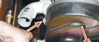
Description of the device and where it is located
With the advent of electronic gasoline injection systems, designers were faced with the task of adjusting the composition of the fuel mixture. For this, oxygen sensors or lambda probes began to be used. The devices maintain the composition of the fuel mixture within certain limits, which allows for maximum efficiency of the catalytic converter. With other mixture compositions, the neutralizer begins to work incorrectly and fails.
Depending on the design of the exhaust system, one or two sensors are used:
- The first is installed directly in the exhaust manifold and measures the composition of the exhaust gases before the catalytic converter. On early systems this device was the only one.
- With the introduction of Euro-3 standards, a second probe began to be used, located after the neutralizer. The electronic control unit analyzes data from two probes and indirectly evaluates the efficiency of the catalyst, and also adjusts the composition of the mixture.
Lambda probe options
Manufacturers have established a service life for products:
- probe without heating coil - no more than 80 thousand km;
- heated unit - up to 100 thousand km;
- planar (broadband) probes - up to 160 thousand km.
The declared service life of the probes is not accurate. The operating life of devices depends on many factors and may be less or more than the specified values.
Chemical reactions in the sensor
If you look closely, the lambda probe readings indicate some voltage. It varies depending on the percentage of oxygen in the exhaust system. A potential appears at the two electrodes. When the amount of oxygen decreases, the voltage increases, and when the amount of oxygen increases, it decreases. The pulse that appears at the output of the device goes to the electronic control unit.
The microprocessor control unit has a built-in memory in which all the main parameters are registered, including the operation of the lambda probe. The controller compares the readings recorded in the memory with those received from the sensor, based on which it adjusts the operation of the fuel injection system.
During operation, chemical reactions are used, which simplifies the design of the device. At the base there is a ceramic tip. As a rule, it is made from zirconium or titanium dioxide. The tip is covered with a layer of platinum (which is why the cost of the sensors is high). The tip and the spray are the two elements that react; they are the electrodes.
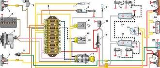
Device diagram
Let's look at the probe diagram, which gives an idea of the placement of nodes. Knowledge of the design allows you to understand the locations of parts that are prone to failure.
Probe design example
- 1 - metal fitting intended for installing a probe, there are turnkey edges on the outer surface, a thread is located below;
- 2 - ceramic insulator;
- 3 — sealing element for inserting the wiring harness;
- 4 - signal wires;
- 5 - metal protective cap, equipped with ventilation vents, designed to protect the measuring element from damage;
- 6 — spring contact part;
- 7 - sensitive element made of ceramic;
- 8 - heating rod;
- 9 - ventilation duct;
- 10 - outer metal casing.
Main symptoms and causes of lambda probe malfunction
The main symptoms of a malfunctioning lambda probe:
- interruptions in operation and floating speed at idle or low shaft speed;
- reduction of vehicle acceleration parameters;
- a noticeable (sometimes by several liters) increase in fuel consumption;
- The Check Engine indicator turns on and errors appear in the memory of the control unit.
The causes of malfunction of the oxygen sensor may be:
- damaged sensor element;
- clogging of the working area of the probe with soot or lead;
- destruction of wiring;
- failure of the heating element.
Lambda probe: signs of malfunction
Sensors of this type do not fail immediately, so before they fail, characteristic signs can be identified:
- falling or floating behavior of engine speed at idle;
- the car begins to twitch, after starting the engine, strange popping sounds are heard;
- Engine power decreases; when you press the fuel pedal, the car reacts with a delay;
- the engine overheats faster and stronger, fuel consumption increases;
- exhaust gases become more toxic.
If the sensor still fails, then the quality of the fuel entering the engine deteriorates greatly. This gives rise to many problems. The reasons for the incorrect operation of the lambda probe are very different:
- The filament circuit does not work properly, and the sensitivity of the sensor tip decreases.
- The quality of the fuel is too low, it contains a lot of iron and lead. Such substances stick to the platinum electrodes of the sensor and render it unusable.
- The lambda probe heating system is not functioning correctly. The data provided is inaccurate.
- The regulator housing overheats. This occurs due to an incorrectly set ignition timing.
- The oil scraper rings are worn out, causing engine oil to enter the exhaust pipe, damaging the sensor.
- The engine is started repeatedly too often.
- To install lambda probes, silicone sealants from hardware stores are used.
- The compression level in the engine cylinders is disrupted, which causes uneven combustion of the fuel mixture.
- The injection nozzles are clogged.
Press the accelerator pedal and release it when the multimeter reads 1 volt. If the value drops sharply to zero, then the sensor is OK. If the data on the display does not jump, but is maintained at a level of 0.4 to 0.5 volts, then the sensor is faulty. Turn off the engine and check all wiring related to the ignition and relay.
Some cars are equipped with an advanced on-board system with different modes. Various signals may indicate certain malfunctions:
- 0130 – sensor readings are incorrect;
- 0131 – the signal coming from the sensor is too weak;
- 0133 – lambda probe responds slowly;
- 0134 – the device does not respond;
- 0135 – malfunction of the lambda probe heater;
- 0136 – grounding of the second sensor is closed;
- 0137 – the second sensor produces a signal that is too weak;
- 0138 – signal from the second sensor is too high;
- 0140 – broken lambda probe;
- 1102 - it is impossible to read the indicators because the resistance of the element is too low or completely absent.
How to check the oxygen sensor?
If the above problems occur, you need to check the condition of the oxygen sensor. The lambda probe is checked visually and using electronic equipment.
Visual inspection
The very first stage of verification is an external inspection of the part, which consists of the following steps:
- Conduct a visual inspection of the wiring and plugs. Melting of insulation, mechanical damage, and oxidation of contacts are unacceptable.
- The working surface of the sensor should be free of soot and soot. A soot layer occurs when piston rings wear out or valves are poorly sealed. Soot changes the sensitivity of the probe, which transmits incorrect information to the engine control unit. After cleaning the part, performance is restored. Cleaning is done with a soft brush and keeping the probe in phosphoric acid for 15-20 minutes.
- If white or light gray deposits are present on the surface of the sensitive element, this indicates the use of fuel with additives based on tetraethyl lead. As a rule, such a sensor quickly fails.
An external inspection of the lambda probe allows you to determine only a small part of the faults; a more thorough analysis is performed using a tester or multimeter.
Checking with a multimeter
The heating circuits in the device may burn out or the working element may begin to deteriorate. These faults can be detected using electronic test instruments.
There are three types of lambda probe plugs:
- two-wire (ground and signal);
- three-wire (a positive power wire for the heating element is added);
- four-wire (there is an additional grounding of the heating coil).
To perform a lambda probe test, factory documentation is required to determine the purpose of the wires and a digital multimeter switched to voltmeter and ohmmeter mode.
Approximate sequence of actions:
- Warm up the engine to operating temperature, since only in this case is it possible to obtain correct data.
- Ring the heating circuits. Under normal conditions, the resistance is in the range of 2-15 Ohms; more accurate data can be obtained from reference literature. Resistance is measured by connecting to two pins in the plug (for a four-wire probe) or to the heater pin and the car body (for three-wire probes). If the resistance is zero, this means that a short circuit in the heating element windings has been detected. The tendency of resistance to infinity is a symptom of a break in the nichrome heating threads.
- Check the wiring going to the heater from the control unit for breaks.
- Check the voltage in the signal circuit. The negative signal can be taken from the car body or directly from the battery terminal. Before checking, the engine should be run at medium speed (2500-3000 rpm) for 2-3 minutes. Disconnect the plug and connect the test device.
- Raise the speed to 2500-2600 rpm and sharply release the gas pedal. The voltmeter readings are in the range of 0.2-1.0 volts and change at a frequency of 1 Hz (on average once per second).
- Disconnect the vacuum tube from the pressure regulator to check the degree of leanness of the mixture. It is possible to force a lean mixture by closing the air intake opening of the throttle assembly with your hand. Measure the voltage, which should be within 0.2 volts or lower.
- Put the handset back.
- Rapidly increase the speed to maximum. In this case, the voltage should be about 1 volt.
Instructions for replacing the sensor yourself
Before starting work, you need to prepare materials and tools:
- New probe.
- A wrench or socket that will allow you to unscrew the sensor housing from the manifold. On some cars, you can try to remove the device with a regular 22 mm open-end wrench or a gas adjustable wrench. But the majority of machines require the use of a specialized attachment.
- Extension for nozzle.
- Torque wrench up to 50-100 N/m.
- Protective gloves and sleeves, since work is performed on a heated collector.
- Wrenches for removing protective heat shields and/or manifold.
Lambda probes should be replaced with the same model or a similar one that matches the parameters. You cannot install the first sensor you come across. Before installation, you must carefully study the instructions supplied by the manufacturer.
Approximate sequence of actions when replacing the first probe:
- Warm up the power unit to operating temperature. In this case, thermal expansion of the exhaust system elements occurs, which makes it easier to unscrew the sensor from the manifold or exhaust pipe.
- Turn off the engine.
- Remove the terminal from the battery to eliminate the possibility of the electric cooling fan starting.
- Carefully disconnect the probe connector from the wiring.
- Wear protective gloves and remove the probe wire from the clamps.
- Using the nozzle, unscrew the probe. At this stage, difficulties are possible, since the junction of the probe and the collector becomes clogged with rust and burnt grease. To facilitate the process, local heating with a gas burner can be used, which allows you to burn out the rust. After this, you should try to pull the probe out of place; if the part does not begin to unscrew, repeat the warming up again.
- Wipe the installation area from any remaining old graphite grease.
- Check the presence of standard lubricant on the threads of the new probe. The product may be included in the package in a separate bag. The lubricant is applied in a thin, even layer to the thread. Application to the protective cap is strictly prohibited, as this leads to the formation of hard deposits and deterioration of the probe’s operating parameters. If the car uses a sensor secured with two bolts, then they do not need lubrication.
- Carefully screw the sensor into place by hand until it stops.
- Tighten the probe with a wrench to the required torque. Most manufacturers indicate a force of 40-45 N/m, but it is recommended to check the value in the service literature. If there is no torque wrench, tightening is done by turning the probe 180º after twisting it by hand until it stops.
- Lay the harness along the clamps, secure with clamps if necessary.
- Connect the battery and clear errors from the control unit. Errors can be cleared using a computer or another method (depending on the make and model of the car).
When installing the probe, the tightening torque must be observed. Excessive force leads to destruction of the probe body or breakage of the thread; low torque causes breakthrough of exhaust gases and uneven heating of the part.
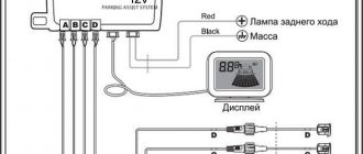
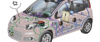
Features of the system
In fuel injection systems, two lambdas can be used. These sensors measure the oxygen content and make it clear to the electronic control unit in which direction it is necessary to adjust the ignition or the composition of the fuel mixture so that the amount of harmful substances in the exhaust is minimal.
Dual sensor systems ensure that the exhaust contains very few pollutants. But the complication of the design leads to the fact that its reliability deteriorates. We filled the car with low-quality fuel a couple of times and ruined the catalyst. And then - incorrect sensor readings, malfunction of the injection system.
And even if you comply with all the requirements, the catalyst will break sooner or later, since its resource is not very long. And the cost of this element, even on the most budget machines, is exorbitant. Therefore, many motorists, in order to save money, cut out the catalyst and replace it with a flame arrester. In fact, this is an ordinary piece of pipe of suitable sizes. And so that the second lambda probe does not give an error, they install a decoy. This is a spacer that is mounted on the sensor.
Using a blende, it is possible to move the flow of gases away from the tip of the sensor. This affects the element readings sent to the electronic control unit. Consequently, the microcontroller detects the difference in readings and does not notice the absence of a catalyst.
How to repair a lambda probe?
Manufacturers of lambda probes position the parts as non-separable and cannot be repaired. However, some car owners, with some success, try to disassemble and repair sensors, assembling one functional one from two or more damaged devices.
The car owner should remember that such a lambda probe repair is a temporary measure. It is recommended to purchase a new sensor and use the repaired one as a spare.
Heating element repair
An approximate sequence for disassembling and repairing a sensor with a damaged heating element:
- Carefully saw through the outer housing of the sensor.
- The second sensor is sawed in a similar way.
- Remove the heating rods from the sawn housings. The entire device must be wiped from carbon deposits and dirt with a dry cloth. The use of cleaning agents is not recommended as chemical reactions may damage the heater.
- Install the heater into the probe that will be used on the car.
- Solder the body with copper-phosphorus solder, which has a melting point of about 700 ºC. A gas jewelry burner is used as a heat source.
- Check the functionality of the product with a tester and install the probe into the collector. If the repaired device does not work, you can try replacing the heater again. Below are photos that explain the repair process.
How much does an oxygen sensor cost?
The cost of the sensor depends on the type of product and the prevalence of the model. Below are reference prices for devices used on some car models.
| Name | Price, rub |
| Lambda probe for VAZ-2114 | 1500-2000 |
| Lambda probe for Hyundai Solaris | 4500 |
| Lambda probe for Volkswagen Polo Sedan | 3500-5000 |
| Lambda probe for Gazelle, Volga | 1600-2600 |
| Prices are relevant for three regions: Moscow, Chelyabinsk, Krasnodar | |
Video “Checking the lambda probe”
Recommendations for checking the lambda probe are shown in the video filmed by the author of the channel “v_i_t_a_l_y”.
I was puzzled by the increased gasoline consumption. I traveled 500 km to Belarus and spent 45 liters, consumption was 9 liters and that was on the highway. Well, I already realized that something was wrong. Having checked all the sensors in principle and ringing them, it turned out that the lambda probe sensor (hereinafter referred to as the oxygen sensor simply DC) reacts very inadequately. I will describe everything further and in detail.
My car uses a 4-wire DC, 2 white sensor heaters, black for signal, gray for sensor ground.
Lambda probe: check.
To check the functionality of the oxygen sensor, you will need: the factory instructions, which will tell you where the lambda probe is located, and a digital voltmeter. These are the main supporting tools. The engine should be warmed up while testing the device. 1. Next, we check the resistance on the wires of the DC heaters. At the required 2-10 ohms I have
It already seems like something is wrong. Okay, let's move on, I'll post a video on measuring voltage. We take the negative from the car body (I even tried and took the battery from the negative) and connect the plus to the black wire and set the voltage. This is what happened: Attempt No. 1
Upd: Small mini instructions. To check the oxygen sensor (lambda probe), connect the negative lead of the multimeter probe to the engine body. Identify the pins on the oxygen sensor. As I already said, there can be from one to four wires. Connect the positive lead of the multimeter probe to the signal wire of the oxygen sensor. Warm up the engine to normal temperature. Accelerate the engine to 2500-3000 rpm for 3 minutes to warm up the oxygen sensor. Run the engine at higher speeds and check that the oxygen sensor turns on. The voltage on the sensor should be from 0.2 to 1 volt and turn on at a frequency of 8-10 times every 10 seconds. If the voltage is approximately 0.45 volts and does not change, then the oxygen sensor simply does not work. Using a tester, check for battery voltage at the oxygen sensor heater power supply. If there is no voltage, check the wires going to the relay or to the ignition switch. Also check the ground connection of the lambda probe heater. — When the oxygen sensor is working and warmed up, the voltage at the signal pin should change from 0.2 to 1 volt with a frequency of 8-10 times in 10 seconds (1 Hz) at an engine speed of 2500 rpm. — When the throttle valve is opened sharply, the multimeter should show a voltage of 1 volt. — When closing the throttle suddenly, show the voltage near zero. At this point, the lambda probe testing procedure can be considered complete.
From all of the above, I still suspect that the sensor is dead. I'm waiting for your opinions and comments. M.b. There are specialists among us who will advise you. Or post your measurements, we will compare, preferably with photos and video recording)))
Excess air coefficient λ
Before disassembling the design of the oxygen sensor and the principle of its operation, it is necessary to decide on such an important parameter as the excess air ratio of the air-fuel mixture: what it is, what it affects and why the sensor measures it.
In the theory of internal combustion engines, there is such a thing as the stoichiometric ratio - this is the ideal proportion of air and fuel at which complete combustion of the fuel occurs in the combustion chamber of the engine cylinder. This is a very important parameter on the basis of which fuel supply and engine operating modes are calculated. It is equal to 14.7 kg of air to 1 kg of fuel (14.7:1). Naturally, such an amount of the air-fuel mixture does not enter the cylinder at one point in time, this is just a proportion that is recalculated for real conditions.
Dependence of power (P) and fuel consumption (Q) on the excess air ratio
We recommend: How does an internal combustion engine work and how does it work?
Excess air factor (λ)
- this is the ratio of the actual amount of air entering the engine to the theoretically necessary (stoichiometric) for complete combustion of the fuel. In simple terms, this is “how much more (less) air entered the cylinder than it should have.”
Depending on the value of λ, three types of air-fuel mixture are distinguished:
- λ = 1—stoichiometric mixture;
- λ < 1 - “rich” mixture (excess - fuel; lack - air);
- λ > 1 - “lean” mixture (excess - air; lack - fuel).
Modern engines can operate on all three types of mixture, depending on the current tasks (fuel economy, intense acceleration, reducing the concentration of harmful substances in exhaust gases). From the point of view of optimal engine power values, the lambda coefficient should have a value of about 0.9 (“rich” mixture), the minimum fuel consumption will correspond to a stoichiometric mixture (λ = 1). The best results for exhaust gas purification will also be observed at λ = 1, since the effective operation of the catalytic converter occurs at a stoichiometric composition of the air-fuel mixture.
What and how can you check the lambda?
To check, you will need a digital voltmeter (preferably an analog voltmeter, since its “sampling” time is much shorter than that of a digital one) and an oscilloscope, if possible, the measurements will be more accurate. Before checking, you should warm up the car since lambda operates correctly at temperatures above 300C°.
First we look for the heating wire:
We start the engine, do not disconnect the lambda connector. We connect the negative probe of the voltmeter (ordinary gauge) to the car body. We “poke” the positive probe on each wire contact and observe the voltmeter reading. When the positive wire of the heater is detected, the voltmeter should show a constant 12 V. Next, using the negative probe of the voltmeter, we try to find the negative wire of the heater. We connect to the remaining contacts of the sensor connector. If a negative contact is detected, the voltmeter will again show 12 V. The remaining wires are signal wires.
Checking the lambda probe with a tester:
We take an electronic constant voltage millivoltmeter and connect it in parallel with the LZ (“+” “-” to the LZ, - to ground), and the lambda probe must be connected to the controller.
When the engine warms up (5-10 minutes), then you need to look at the voltmeter needle. It should periodically move between 0.2 and 0.8 V (i.e. 200 and 800 mV, and if less than 8 cycles occur in 10 seconds, it’s time to change the LZ. Also replace if the voltage “stands” at 0 .45 V.
When the voltage is always 0.2 or 0.9 V, then there is something wrong with the injection - the mixture is too lean or too rich. Since the oxygen sensor voltage should change all the time and jump from ≈0.2 to 0.9V.
There is another quick way to check the lambda probe . You should do this:
Carefully pierce the positive contact of the tester (black lambda wire), the other contact to ground. With the engine running, the readings should range from 0.1 to 0.9V. Constant readings (for example, 0.2 all the time) or readings that go beyond this range, or fluctuations with a smaller amplitude indicate a malfunction of the probe.
- all the time 0.1 - little oxygen
- all the time 0.9 - a lot of oxygen
- The probe is fine, the problem is something else.
If you have the time and desire to bother, you can conduct several tests on a rich and lean mixture and additionally check the lambda probe sensor .
- Disconnect the oxygen sensor from the block and connect it to a digital voltmeter. Start the car and, by pressing the gas pedal, increase the engine speed to 2500 rpm. Using a device for enriching the fuel mixture, reduce the speed to 200 per minute.
- If your vehicle is equipped with an electronically controlled fuel system, remove the vacuum tube from the fuel pressure regulator. Look at the voltmeter reading. If the instrument needle approaches the 0.9 V mark, it means the lambda probe is in working condition. A malfunction of the sensor is indicated by the lack of response from the voltmeter, and its readings are less than 0.8 V.
- Do a lean mixture test. To do this, take a vacuum tube and provoke an air leak. If the oxygen sensor is working properly, the digital voltmeter reading will be 0.2 V or lower.
- Check the operation of the lambda probe in dynamics. To do this, connect the sensor to the connector of the fuel supply system, and install a voltmeter parallel to it. Increase engine speed to 1500 rpm. The voltmeter readings with a working sensor should be at the level of 0.5 V. Another value indicates a failure of the lambda probe.
Checking the voltage in the heating circuit
To check the presence of voltage in the circuit, you need a voltmeter. We turn on the ignition and connect it with probes to the heater wires (you cannot disconnect the connector, it is better to pierce it with sharp needles). Their voltage should be equal to what the battery produces when the engine is not running (about 12V).
If there is no plus, you need to go through the battery-fuse-sensor circuit, since it always goes directly, but the minus comes from the ECU, so if there is no minus, look at the circuit to the block.
Checking the lambda probe heater
In addition to measuring voltages with a multimeter, you can also measure resistances to check the serviceability of the heater (two white wires), but you will need to switch the tester to Ohms. The documentation for a particular sensor must indicate the nominal resistance (usually it is about 2-10 Ohms), your task is only to check it and draw a conclusion. The video shows this method:
”
What is a lambda probe
It is known that for the combustion of 1 kilogram of fuel, 14.7 kilograms of air are needed. This ratio is ideal, which means it guarantees proper engine operation in all modes. Obtaining this value is not easy, but it is necessary to constantly achieve its creation when changing the throttle position. This is what the oxygen sensor is designed for.
In fact, the word “oxygen” is used erroneously, since the air component does not affect the operation of the device in any way.
The lambda probe is designed to capture gasoline vapors that have not burned in the engine cylinder. It is installed in the exhaust system and most often used in conjunction with another sensor of the same type. The essence of the action is extremely simple - one device is installed before the catalyst, and the other after. At their ends, inside the exhaust, electrodes are installed, which are coated with a special chemical composition that reacts to fuel particles.
If the mixture is too rich, they become electrified and produce voltage, which is taken from the ends of the sensor and then transmitted to the electronic control unit. Since two devices are used at once, the ECU processes the difference in readings and concludes that the mixture needs to be leaner, and this is done very quickly in real time. The same thing happens with a lean mixture, which creates a minimum voltage at the output, which indicates the need to enrich the mixture.