What does a car owner need to consider before replacing?
In order to correctly connect LED light bulbs with your own hands, using a connection diagram, you first need to understand the basic information. First you need to understand that a 12-volt blinking car diode is not a lamp.
Connecting LEDs to a 12-volt on-board network should be done taking into account some points:
- First of all, to secure the connection, you need to take into account the voltage that is present in the car electrical network. As a rule, this parameter is about 12-13 volts when the engine is off and about 13-14.5 volts when the engine is running.
- On average, one bright and powerful diode requires 3.5 volts of power, but this figure can also vary depending on the color. For example, a yellow or red flashing LED for a car will consume about 2.3 volts, and white or blue elements will consume 3.5 volts on average.
- Unlike standard incandescent light bulbs, LED assemblies provide better illumination of the surrounding surface, which is especially good for installation in dashboards.
- Before purchasing, you should check the type of lens installed in the light bulb. There are highly targeted devices equipped with small lenses.
- Regardless of the type, twelve-volt diode elements have both a positive and negative terminal. The positive contact in this case is the anode, and the negative contact is the cathode.
LEDs with different bases
To choose the right 12V diode elements, you need to navigate their varieties, and they are divided among themselves by power:
- Low-power devices do not have a cooling system, so their service life is usually short. In cars, it makes sense to use such devices only as indicators, for example, when turning on daytime running lights or when installing a battery discharge controller.
- Powerful 12V diodes have a longer service life; if used correctly, they can last up to 10 years. It must be taken into account that such diode elements are not subject to heavy loads.
- Modules Such devices are a steel plate on which a number of diode elements are mounted. The price of a module depends on its reliability and production quality - the better the quality, the higher the price. The modules should not be confused with Chinese tapes, since their operation is possible, perhaps, to illuminate the control panel or glove compartment.
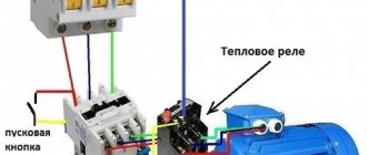
Diagram for connecting a diode in a car
Instructions for connecting LEDs
How to connect an LED to your car? What resistance should be selected for the LED? Do I need to use resistors?
Below we will describe how the diode module should be connected:
- The procedure for connecting LEDs to a 12-volt network begins with calculating the power supply. The main disadvantage of clusters is that their brightness will depend on changes in engine speed. If the rpm drops, the power will also decrease. Consider the fact that the most optimal indicator for a good glow of clusters is the voltage parameter of 12.5 volts - if it is lower, the glow will be weak.
- The cluster design includes diode elements and a resistor, which, by the way, is an important component of any cluster. The resistor device used to absorb excess voltage is installed at the rate of one per three diode elements. So if you bought a whole strip to install in an optic, you will most likely need to cut it. Moreover, circumcision should be carried out only on certain segments.
- The connection procedure is carried out in a sequential manner. That is, you will need to first make a cluster by connecting several diodes to each other in turn, and the ends of the cluster are connected to the on-board network. As an example, consider white diode components with a power of 3.5 volts. For a regular 12 V on-board network, you will need three diode bulbs, which will consume a total of 10.5 volts. Daisy chaining means that the positive terminal of one component must be connected to the negative terminal of another.
- There is no need to directly connect the cluster yet; a resistance, that is, a resistor, is connected in series. It should be taken into account that the resistance should be about 100-150 Ohms, and the resistor power parameter should be 0.5 W (the author of the video is the Auto Repair and Tuning channel).
Parallel connection method
To connect an LED to 12 volts in parallel, follow these steps (an example is considered with a 3.5 volt diode element and a current of 20 mA):
- Measure the voltage where the light source will be connected to ensure that the connection will be effective. For example, this is 13 volts.
- After this, 3.5 volts of the diode are subtracted from 13 volts, resulting in 9.5 volts. All measurements are made using Ohm's formula - in our case, 20 mA is divided by 100, resulting in 0.02 A.
- The same formula is used to calculate the resistance; to do this, 9.5 volts must be divided by 0.02. As a result, we find out that we need a 475 Ohm resistor.
- The next step is to calculate the power - you need to know this in order to prevent overheating of the resistor element. According to our parameters, 9.5 is multiplied by 0.02 - we get 0.19 W. To prevent possible failures, power can be taken in reserve.
- Next, using a multimeter, the current is measured in the area between the diode lighting source and the resistor element. After this, the tester is set to 10 amperes, and the positive terminal of the device must be connected to the battery positive, the negative terminal to the lamp positive.
- Ultimately, a reading of around 20 mA should appear on the multimeter display. Depending on the light source, as well as the resistance used, the parameters may differ.
DIY LEDs for cars
DIY LEDs for cars
Many car enthusiasts would like to replace the standard incandescent light bulbs in their cars with LEDs. The advantage of the latter is undoubtedly - low current consumption, durability, higher light output, no heating. It's nice to leave the headlights on and discover in the morning that the battery had no intention of being discharged. This article will help you replace car light bulbs with LEDs yourself and avoid common mistakes.
The first thing you must understand before you begin the replacement procedure is that an LED is not a light bulb. Be careful and attentive; repairing your car's electrical equipment as a result of your wrong actions is not a pleasant thing. This, however, applies not only to LEDs, but also to any actions with electrical wiring, be it installing an amplifier or additional signals. But, nevertheless, it is not the gods who burn the pots, there is nothing complicated in such a replacement, any person with straight hands is able to do it on his own.
The main points that we need to learn:
1. Voltage in the vehicle’s on-board network. Typically this is 12 - 13 V when the engine is off and 13 - 14.5 V when the engine is running. 2. The supply voltage of a typical LED is 3.5 V. Depending on the color, this can be: for yellow and red LEDs - 2 - 2.5 V; for blue, green, white - 3-3.8 in. The typical current of a low-power LED is 20 mA, and a high-power LED is 350 mA. 3. Not all LEDs, unlike light bulbs, illuminate the space around them. This must be taken into account when replacing indicator lamps, for example, in the dashboard. When purchasing, you should pay attention to the type of lens or, if possible, ask the seller. Narrow-beam LEDs have a small lens at the end. In general, try to check this when purchasing, or even better, buy and try several different ones. 4. An LED, like a battery, has a plus and a minus. The minus is called the cathode, the plus is the anode; in the diagrams they are depicted like this:
Attention! It should be clear to you that simply plugging in an LED into the car’s on-board network means you are guaranteed to burn it out. Want to make sure? Take and connect any cheap LED directly to the on-board network. From a lighter, for example. It will shine beautifully and smoke, but you will imagine what the process looks like. Expensive LEDs burn out in the same way, so it’s better to train on cheap ones.
Connecting LEDs
1. LED sockets, so-called clusters, are sold on sale; they are designed for 12V power supply. You can simply connect them to the on-board network and enjoy the beautiful lights. But there is an unpleasant feature - when the engine speed changes, the brightness of the LEDs in the clusters will change. Slightly, but noticeable to the eye. In addition, in fact, they glow normally at a voltage of about 12.5V, so if you have low voltage in the on-board network, the clusters will glow dimly. Structurally, the cluster consists of a chain of LEDs and a resistor. For every three LEDs there is a resistor that suppresses excess voltage. The LED strip is designed in exactly the same way, so if you need to cut a piece, look at the strip, there are places on it where you can cut it. Usually these are the same three LEDs and a resistor... You can’t cut anywhere
Related article: Wallpaper for a hall in Khrushchev: choosing options
2. Turn on the LEDs in series, in a chain, that is, make a homemade cluster. That is, connect the required amount to each other, and the remaining two outputs to the on-board network. Let's make a reservation that we are talking about white LEDs. LEDs of different colors have different voltages. It is easy to calculate that for 12-14 V you will need 3 LEDs. In total they will give 3.5 x 3 = 10.5 v. As mentioned above, an LED has a plus and a minus. A connection in series is when the plus of one is connected to the minus of the next, and so on until the end of the chain.
But you still can’t connect them directly; you need to connect a resistor (resistance) that absorbs excess voltage in series with your chain - with a nominal value of approximately 100-150 Ohms, with a power of 0.5 W. Resistors are sold at any amateur radio store.
This method suffers from the same drawback as the previous one - a change in the intensity of the LEDs when the speed changes. Small, but unpleasant. However, using this circuit you can connect any number of LEDs, assembling them in chains of 3 pieces. with a resistor and switching in parallel. In parallel, this means collecting several identical chains, connecting the plus of each chain with the plus of another chain, and the minus with the minus. In general, the resistor value is calculated using Ohm's law. But if you are not comfortable with formulas, use a simple rule: if you turn on 1 LED, you need a 500 Ohm resistor, if you turn on two LEDs, 300 Ohms, three LEDs, 150 Ohms. In this case, you don’t have to read further. But after spending half an hour studying a simple formula, you will learn to select the correct resistor values, which means your LEDs will shine for a long time and correctly. I can assure you that you don’t need to be an academician, I will try to explain it in detail and clearly. You will need:
1. A device measuring voltage, current and resistance, commonly known as “Tseshka” or “Multimeter”. Sold in amateur radio stores, electrical goods stores and Chinese markets. Costs from 50 rubles. I recommend buying a digital one, it’s clearer. With this thing you can make all the necessary measurements, if, of course, you study the instructions or the article “Multimeter for Dummies.”
2. Ohm's law for a section of an electrical circuit, that is, for your LED and resistor. R=U/I. Where R is the resistance of the resistor, U is the voltage that needs to be extinguished, I is the current in the circuit. That is, to get the resistance of the quenching resistor, you need to divide the voltage that needs to be quenched by the current that needs to be received.
Let's look at an example. We have a simple white LED that we need to connect to the car's on-board network. The supply voltage of such an LED is approximately 3.5 V, the current is 20 mA.
1. We measure the voltage at the point to which we are going to connect the LED. The fact is that the voltage in the on-board network is different. There may be 13 volts on the battery, 13.5 on the cigarette lighter, etc. Therefore, decide in advance where you will connect. Turn the device into voltage measurement mode and take measurements. Let's say this is the 13th century. Write it down on a piece of paper.
Related article: What is the best way to process wood?
2. Subtract the LED supply voltage (3.5V) from 13V. We get 9.5 v. The current is inserted into the formula in amperes, one ampere is 1000 milliamps, that is, in our case, 20 mA is 0.02 A. Using the formula, we calculate the resistance:
9.5/0.02=475 Ohm.
To prevent the resistor from heating up during operation, we calculate its power. To do this, you need to multiply the voltage that the resistor extinguishes - 9.5 volts, by the current that passes through it - 0.02 amperes. 9.5x0.02= 0.19 watts. It is better to take a resistor with a reserve - 0.5-1 watt.
That is, we need to tell the seller in the radio store “I need a 475 Ohm 0.5 or one watt resistor.” You can use a higher value, but the LEDs will shine dimmer. Smaller will be brighter, but he may not like it.
Having purchased what you are looking for, we connect and rejoice. To finally make sure that the calculations are correct, you can measure the current in the circuit. To do this, you need to turn on the multimeter in current measurement mode (see the instructions for the device) in the gap between the resistor and the LED. If the instructions are lost, no problem. Set the disk to the “10A” mark, and switch the red probe into the socket labeled “10A”.
It should read 20 milliamps or less. Resistors and LEDs have a range of parameters, so the current may differ in both directions, but only slightly. If the value is from 15 to 23 mA, it is normal. The higher the current, the brighter the LED shines, but the shorter its service life. Therefore, for conventional LEDs it is not recommended to set the current above 20 mA, optimally 18 mA. The best way to select the desired resistance is to use a variable resistor. But it's more complicated
The above information will allow you to connect any number of low-power and high-power LEDs; it is enough to know their operating voltage and current and substitute them into the formula. It can be very useful to connect a regular diode of any type in parallel to the LED in reverse polarity, that is, the cathode of the diode to the anode of the LED. This will protect your LED from reverse polarity voltage. This is especially true for domestic cars of venerable age.
For the most inquisitive - the first LED driver for cars
Further information is intended for advanced amateurs who have already mastered Ohm's law. There is no limit to perfection, and it’s not enough for you to just light the LEDs - you want them to shine evenly, regardless of engine speed.
The most correct way to turn on LEDs is through a current stabilizer. An LED is a semiconductor device that is powered by current rather than voltage. Therefore, if you stabilize and limit the current flowing through it, you can connect at least a kilovolt, the LED will light normally. And how long the LED will shine without losing brightness depends on the operating mode. To stabilize the current, devices called drivers are used. The simplest driver is a circuit based on the LM317 stabilizer chip. The main advantage of this chip for beginners is that it is very difficult to burn
Related article: How to make homemade machines from plywood?
Are you scared? Nothing In essence, two parts are required - the microcircuit itself - a three-terminal voltage stabilizer, which we will turn on in current stabilization mode, and a resistor. In order not to go into theory, the steps are as follows - we purchase a variable resistor with a resistance of 0.5 kOhm. This is a thing with three terminals and a twist. Like the microcircuit, it is sold in the same “Radio Amateur” for ridiculous money. You can even pick it out of an unnecessary household appliance. We solder the wires to the middle pin and one of the outer ones, no matter which one. Turn on the multimeter in resistance measurement mode. We connect the device to the wires and measure the resistance of the resistor. By rotating the rod we achieve the maximum reading, that is, 500 Ohms (or so). This is to avoid burning out the LED if the resistor value is too low.
We assemble the chain. Attention! Carefully check that the connections are correct before connecting? Have you checked? Exactly?
We turn on the device in current measurement mode. By rotating the variable resistor slider, we achieve a device reading of 20 mA. We disconnect the circuit, measure the resistance of the resistor and solder in a regular resistor with the same resistance instead. Voila! You have just assembled your first LED driver. It has a maximum current limitation of 1-1.5 A, so when connecting a large number of LEDs: first, use a higher power resistor. Secondly, touch the chip. If it’s hot, it makes sense to attach it to the radiator. Do not forget that the car body has electrical contact with the negative side of the battery, and the chip substrate (body) has electrical contact with its second leg. Therefore, attaching it to the body without an insulating gasket is a bad idea. Another nuance is that the microcircuit itself reduces the maximum voltage that can be applied to the LED by two to three volts. Therefore, you will not get more than 11-12 volts with such a driver. But it is simple and will give you the first idea about the correct connection of LEDs in a car. By the way, on the same chip + a couple of parts you can assemble an adjustable power supply of 1.5-30 V, which can be very useful in a car. There are many connection schemes on the Internet.
In general, if you succeeded, welcome to the fascinating world of radio electronics, because you are unlikely to stop now...
The best posts
- DIY winches (diagrams and drawings)
- Knitted sweater for a boy: raglan for a baby 1-3 years old with photos and videos
- Amigurumi cat. Description of crochet
- Original DIY hanging shelf for wine and glasses
- How to make a jelly rag (velcro for dust) for cleaning with your own hands
- Crochet SNAIL amigurumi
- DIY folding PVC picnic chair
- DIY electronic bite alarm
Video “Features of connecting diode lamps in cars”
What needs to be taken into account and what mistakes should not be made - recommendations from a specialist in connecting diode lighting sources are given in the video below (author - Amateur Radio channel).
12 V power supplies are widely used due to their versatility and practicality. This voltage is both safe for humans and sufficient for the operation of many electrical appliances. LEDs were no exception. Today, the range of LEDs has expanded so much that connecting them to 12 volts is not entirely easy. Even 12-volt LEDs with a similar voltage drop require knowledge of certain nuances. In this article we will try to understand in as much detail as possible all 12 V power sources and give practical recommendations for connecting any LEDs to them.
How to determine LED polarity
All 12 volt LEDs (white, red, blue and other colors) have an anode and a cathode (polarity). These must be taken into account when connecting LEDs. Polarities can be determined in one of the following ways:
- By design. One of the legs on the light bulb base is always several mm longer. This is the anode. It is marked with a “+” sign or a green dot.
- One bowl inside the flask. If you look closely, you can see two crystals on it. The larger one represents the cathode. The smaller one is the anode.
- Using a multimeter. To do this, the device must be set to “Dialing” mode. Then the probes of the device are brought to the cathode and anode. The first one is black, the second one is red. When they are positioned correctly, the light bulb should glow. If this does not happen, it means that the master incorrectly identified “+” and “-”. You need to change the position of the probes. If this does not help, the LED is simply faulty.
Sometimes craftsmen determine the polarity of LEDs using a battery. But it's painstaking. It is better to use the above methods.
A little theory
An LED is characterized by two main parameters: the rated forward current and the forward voltage drop measured at that current. Both values are nominal and based on them we can draw a conclusion about the power consumption of the LED. By smoothly increasing one of the parameters (for example, voltage), you can use a multimeter to record the second parameter (current).
The result will be another important parameter inherent in any diode - the current-voltage characteristic (volt-ampere characteristic). It is nonlinear and clearly proves that even a slight excess of the rated forward voltage leads to a sharp increase in current and, consequently, to degradation of the semiconductor crystal.
In addition, all light-emitting diodes have a low reverse voltage (about 5 V). Therefore, before turning on the LED for the first time, you need to re-check that the polarity is correct. To protect the LED from reverse polarity, you can install a conventional diode with a high reverse voltage in parallel with it.
Types of 12 V power supplies
An LED of any type must be connected to a power source (PS) with a stabilized output current. However, manufacturers of LED lamps often skimp on quality and install inexpensive power supplies with no stabilization.
The most common are transformerless 12 V power supplies with a quenching capacitor and a current-setting resistor at the output. Such schemes lack any stabilization and protection. As a result, surges in the mains voltage are not leveled out and negatively affect the operation of the lamp. However, the circuit is so cheap that it is often found in LED lamps and other devices.
When connecting low-power LEDs from a battery with a supply voltage of 12 V, you can limit yourself to a resistor that is correctly selected in terms of resistance and power. The exception is the vehicle's on-board network, in which the voltage can fluctuate widely. So when designing an LED circuit, for example for a car, you cannot do without a current stabilizer (driver).
In the simplest case, you can construct a driver yourself using a linear IC LM317T, which costs about $0.2. In this case, to obtain a stable voltage of 12 V, a minimum set of elements in the harness is sufficient. With a total current through the LEDs of up to 300 mA, it works perfectly without additional cooling. A typical circuit for connecting the LM317T as a current stabilizer is shown below.
There are also unstabilized power supplies, in which the following are connected in series: a step-down transformer, a rectifier and a capacitive filter (capacitor). Their use is justified only in residential areas with stable network voltage, since any occurrence of surges and impulse noise will negatively affect the operation of LEDs.
For LEDs, 12 V switching power supplies are much more reliable. They guarantee high efficiency, stable output current and voltage during power supply fluctuations.
A computer power supply can be considered a type of 12 V switching power supply. In older 250W models, the +12V output load capacity is 10A, which is more than enough to drive several high-power LEDs even with a 12V voltage drop. If the size and noise of the fan are not a hindrance, then a used computer power supply can be given a second life.
If the form factor and aesthetic indicators matter, then for an LED or LED assembly it is better to buy a ready-made 12 V power supply. Its cost greatly depends on the power and design option (with or without a housing).
For those who are not well versed in electricity, let us remind you that there are 12 V AC voltage sources. Inside such a block there is a step-down transformer with a fuse, and on the case there is an inscription: “Output AC 12 V”, which means: “output AC voltage 12 IN". It is prohibited to directly connect LEDs to it. To use it in LED lighting, you need to at least supplement the circuit with a diode bridge, a capacitor and a current stabilizer on the LM317T.
Methods for connecting LEDs to a 12 volt power supply
To connect one 3 V LED to a 12 volt stabilized power source, you will have to compensate for the excess (about 9 V) with a resistor or zener diode. This is extremely inefficient, since the bulk of the energy will be dissipated on the auxiliary elements of the circuit.
To increase the efficiency of the circuit, the LEDs are connected in series in threes. If we consider that the voltage drop on the most common white LEDs is approximately 3.3 V, then one low-power resistor is enough to extinguish the remaining 2 V (12-3.3*3=2). Yellow and red LEDs can be combined in series in groups of 5, since their voltage drop does not exceed 2.2 V.
Ideally, before calculating the resistor, you need to know exactly the operating voltage of each LED. You can take it from your passport or measure it yourself. The measurement is made with the LED turned on, through which the rated current flows. Then, according to Ohm’s law, the rating and power of the current-limiting resistor are determined: R=Upit-(ULED1+ ULED2+…+ ULEDn)/ILED. P=(Upit-(ULED1+ ULED2+…+ ULEDn))*ILED.
Calculation of a resistor using the example of one LED
You can use an example to see what resistor is needed for a specific LED to connect it to a car battery (12-14.5 V). The calculations use a higher voltage rating.
If the lamp consumes 3.3 V, then 14.5-3.3 = 11.2 V remains for resistance.
For a current of 20 mA: R = 11.2/0.02 = 560 Ohm.
Power: P=0.022 *560 = 0.2240 W.
It is better to buy a 0.25 W resistor. You can solder it to both the anode and the cathode, if the polarity is observed when connecting the LED light bulb.
Detailed algorithm for turning on the LED to 12 V
Based on the above information, we will create a step-by-step algorithm for connecting LEDs to a 12 V power source. 1) Determine the type of power supply:
- If the power supply looks like a network adapter, then you can find out its type by its weight. A pulse-type device will weigh 100-200 g, which is 2-3 times less than the mass of a linear analogue;
- from the inscription on the case, find out the type of voltage at the output (DC, AC);
- from the inscription find out the power and maximum current that it is capable of delivering to the load, that is, to the LEDs;
- plug the power supply into the network and measure the output voltage with a multimeter to make sure it is working properly.
2) By the type of LED, find out its rated current, voltage and power consumption. 3) Draw a conclusion about the possibility of connecting an LED to an existing power supply. For example, there is a pulse adapter with the following parameters:
- input voltage – AC: 230 V
50 Hz;
- output voltage – DC: 12 V = 1 A;
- power – 12 W.
You can connect 3 identical blue, green or white LEDs in series to it through a resistor, calculating its value using the above formula. Their rated current should not exceed 700 mA. Then the load power will not exceed: P=PLED1+ PLED1+PLED1+PR=3.3*0.7+3.3*0.7+3.3*0.7+2*0.7=8.3 W .
The remaining power reserve will allow the adapter to operate for a long time and stably without overload. 4) The LEDs should be connected with correct polarity, and the resistor can be placed in any part of the electrical circuit. 5) All contacts of the finished device must be securely sealed and insulated after successful startup.
LEDs are modern, economical, reliable radioelements used for light indication. We think everyone knows about this! It is based on this experience that there is such a high desire to use LEDs for designing a wide variety of electrical circuits, both in consumer electronics and for cars. But here certain difficulties arise. After all, the most common LEDs have a supply voltage of 3...3.3 volts, and the on-board voltage of the car is nominally 12 volts, and sometimes rises to 14 volts. Of course, a logical assumption arises here that in order to connect the LEDs to the 12 volt network of the machine, it will be necessary to lower the voltage. The article will be devoted to this topic, connecting the LED to the vehicle’s on-board network and reducing the voltage.
How to connect an LED to 12 volts
LEDs have long been used in various spheres of people's lives and activities. Due to their qualities and technical characteristics, they have gained wide popularity. Based on these light sources, original lighting designs are created. Therefore, many consumers quite often have the question of how to connect an LED to 12 volts there. This topic is very relevant, since this connection has fundamental differences from other types of lamps. Please note that only direct current is used to operate LEDs. It is of great importance to observe the polarity when connecting, otherwise the LEDs simply will not work.
Connecting an LED through a resistance to 12 volts in a car (via a resistor)
Let's start, as in the paragraph above, with the option of connecting the LED to a voltage of 12 volts through a resistor. In order for you to better understand how the voltage drop occurs, we will present several options. When 3 LEDs are connected to 12 volts, 2 and 1.
Connecting 1 LED through a resistance to 12 volts in a car (via a resistor)
So we have an LED. Its supply voltage is 3.3 volts. That is, if we took a 3.3 volt power source and connected an LED to it, then everything would be great. But in our case, there is an increased voltage, which is not difficult to calculate using the formula. 14.5-3.3= 11.2 volts. That is, we need to initially reduce the voltage by 11.2 volts, and then only apply voltage to the LED. In order for us to calculate the resistance, we need to know what current flows in the circuit, that is, the current consumed by the LED. On average, this is about 0.02 A. If you wish, you can look at the rated current in the datasheet for the LED. As a result, according to Ohm's law, it turns out. R=11.2/0.02=560 Ohm. The resistance of the resistor is calculated. Well, drawing a diagram is even easier.
The resistor power is calculated using the formula P=UI=11.2*0.02=0.224 W. We take the closest one according to the standard series.
Connecting 2 LEDs through a resistance to 12 volts in a car (via a resistor)
By analogy with the previous example, everything is calculated the same way, but with one condition. Since there are already two LEDs, the voltage drop across them will be 6.6 volts, and the remaining 14.5-6.6 = 7.9 volts will remain for the resistor. Based on this, the scheme will be as follows.
Since the current in the circuit has not changed, the power of the resistor remains unchanged.
Connecting 3 LEDs through a resistance to 12 volts in a car (via a resistor)
And one more option, when almost all the voltage is extinguished by LEDs. This means that the resistor will be even smaller in value. Total 240 ohms. A diagram for connecting 3 LEDs to the machine's on-board network is attached.
Finally, all we have to say is that the calculations used a voltage of not 12, but 14.5 volts. It is this increased voltage that usually occurs in the electrical network of the car when it is started. It is also not difficult to estimate that when connecting 4 LEDs, you will not need to use any resistor at all, because each LED will have 3.6 volts, which is quite acceptable.
Calculation of LED connections in 12 and 220 volt circuits
A separate LED cannot be connected directly to a 12V power source because it will burn out immediately. It is necessary to use a limiting resistor, the parameters of which are calculated using the formula: R= (Upit-Upad)/0.75I, in which R is the resistance of the resistor, Upit and Upad are the supply and drop voltages, I is the current passing through the circuit, 0.75 – LED reliability coefficient, which is a constant value.
As an example, we can take the circuit used to connect 12-volt LEDs in a car to a battery. The initial data will look like this:
According to the formula above, the resistance value will be as follows: R = (12 – 2.2)/0.75 x 0.01 = 1306 ohms or 1.306 kohms. Thus, the closest would be a standard resistor value of 1.3 kOhm. In addition, you will need to calculate the minimum resistor power. These calculations are also used when deciding how to connect a powerful LED to 12 volts there. The actual current value is preliminarily determined, which may not coincide with the value indicated above. For this, another formula is used: I = U / (Rres. + Rlight), in which Rlight is the resistance of the LED and is defined as Up.nom. / Inom. = 2.2 / 0.01 = 220 Ohm. Therefore, the current in the circuit will be: I = 12 / (1300 + 220) = 0.007 A.
As a result, the actual voltage drop of the LED will be equal to: Udrop.light = Rlight x I = 220 x 0.007 = 1.54 V. The final power value will look like this: P = (Usupply - Udrop)² / R = (12 - 1.54)²/ 1300 = 0.0841 W). For practical connection, it is recommended to increase the power value slightly, for example to 0.125 W. Thanks to these calculations, it is possible to easily connect an LED to a 12 volt battery. Thus, to properly connect one LED to a 12V car battery, you will additionally need a 1.3 kOhm resistor in the circuit, the power of which is 0.125 W, connecting to any contact of the LED .
The calculation of connecting an LED to a 220V network is carried out according to the same scheme as for 12V. As an example, we take the same LED with a current of 10 mA and a voltage of 2.2V. Since the network uses alternating current with a voltage of 220V, the calculation of the resistor will look like this: R = (Up.-Up.) / (I x 0.75). By inserting all the necessary data into the formula, we get the real resistance value: R = (220 - 2.2) / (0.01 x 0.75) = 29040 Ohm or 29.040 kOhm. The closest standard resistor value is 30 kOhm.
Next, the power calculation is performed. First, the value of the actual consumption current is determined: I = U / (Rres. + Rlight). The LED resistance is calculated by the formula: Rlight = Up.nom. / Inom. = 2.2 / 0.01 = 220 Ohm. Therefore, the current in the electrical circuit will be: I = 220 / (30000 + 220) = 0.007A. As a result, the actual voltage drop across the LED will be as follows: Udrop.light = Rlight x I = 220 x 0.007 = 1.54V.
To determine the power of the resistor, the formula is used: P = (Upit. - Upad.)² / R = (220 -1.54)² / 30000 = 1.59 W. The power value should be increased to the standard 2W. Thus, to connect one LED to a network with a voltage of 220V, you will need a 30 kOhm resistor with a power of 2W.
However, alternating current flows in the network and the light bulb will burn in only one half-phase. The light will flash quickly at 25 flashes per second. For the human eye, this is completely invisible and is perceived as a constant glow. In such a situation, reverse breakdowns are possible, which can lead to premature failure of the light source. To avoid this, a reverse directional diode is installed to ensure balance in the entire network.
Connecting an LED through a voltage stabilizer to 12 volts in a car (via a microcircuit)
Now let's move on to a stabilized 12-volt LED power supply circuit. Here, as we have already said, there is a circuit that regulates its own internal resistance. Thus, the LED will be powered steadily, regardless of voltage surges in the on-board network. Unfortunately, the disadvantage of using the microcircuit is the fact that the minimum stabilized voltage that can be achieved will be 5 volts. It is with this voltage that you can find the most widely known microcircuits - stabilizers KR142 EH 5B or a foreign analogue L7805 or L7805CV. Here the only difference is in the manufacturer and the rated operating current from 1 to 1.5 A.
So, the remaining voltage from 5 to 3.3 volts will have to be extinguished according to the same example as in previous cases, that is, by using a resistor. However, reducing the voltage with a resistor by 1.7 volts is no longer as critical as by 8-9 volts. Voltage stabilization in this case will still be observed! Here is a wiring diagram for the stabilizer chip. As you can see, it is very simple. Anyone can implement it. No more difficult than soldering the same resistor. The only condition is the installation of a radiator that will remove heat from the microcircuit. It is necessary to install it. The diagram says that the microcircuit can power 10 LED circuits, but in fact this parameter is underestimated. In fact, if about 0.02 A passes through the LED, then it can power up to 50 LEDs. If you need to provide power to a larger quantity, then use a second identical independent circuit. Using two microcircuits connected in parallel is not correct. Since their characteristics are slightly different from each other, due to individual characteristics. As a result, one of the microcircuits will have a chance to burn out much faster, since its operating modes will be different - overestimated. We have already talked about the use of similar microcircuits in the article “5-volt charger in a car.” By the way, if you still decide to power the LED using PWM, although it’s hardly worth it, then this article will also reveal to you all the secrets of implementing such a project.