Starter control buttons
In general, you will need two buttons: one to turn it on and one to turn it off. Please note that they use contacts with different purposes to control the starter. For the “Stop” button they are normally closed, that is, if the button is not pressed, the group of contacts is closed, and opens when the button is activated. The Start button is the opposite.
These devices can either contain only a specific element needed for operation, or be universal, including one closed and one open contact. In this case, you need to choose the right one.
Manufacturers usually provide their products with symbols that make it possible to determine the purpose of a particular contact group. The stop button is usually painted red. The launcher color is traditionally black, but green is welcome, which corresponds to the “On” or “Turn on” signal. Such buttons are mainly used on cabinet doors and machine control panels.
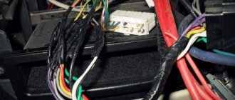
For remote control, push-button stations are used, containing two buttons in one housing. The station is connected to the starter installation location using a control cable. It must have at least three cores, the cross-section of which may be small.
The simplest working circuit of a starter with a thermal relay
Magnetic switch
Now about what you should pay attention to when examining the starter itself before connecting it. The most important thing is the voltage of the control coil, which is indicated either on it itself or nearby. If the inscription reads 220 V AC (or there is an AC icon next to 220), then a phase and a zero are required for the control circuit to operate.
Watch an interesting video about the operation of a magnetic starter below:
If it is 380 V AC (the same alternating current), then the starter will be controlled by two phases. In the process of describing the operation of the control circuit, it will become clear what the difference is.
With any other voltage values, the presence of a direct current sign or the letters DC, it will not be possible to connect the product to the network. It is intended for other circuits.
We will also need to use an additional contact of the starter, called a block contact. For most devices, it is marked with the numbers 13NO (13NO, simply 13) and 14NO (14NO, 14).
The letters NO mean “normally open”, that is, it closes only when the starter is pulled in, which can be checked with a multimeter if desired. There are starters that have normally closed additional contacts; they are not suitable for the control circuit under consideration.
Power contacts are designed to connect the load, which they control.
Their markings vary from manufacturer to manufacturer, but there are no difficulties in identifying them. So, we attach the starter to the surface or DIN rail in the place of its permanent location, lay the power and control cables, and begin the connection.
220 V starter control circuit
One wise man said: there are 44 schemes for connecting buttons to a magnetic starter, of which 3 work, and the rest do not. But there is only one correct one. Let's talk about it (see diagram below).
It is better to leave connecting the power circuits for later. This will make it easier to access the coil screws, which are always covered by the main circuit wires. To power the control circuits, we use one of the phase contacts, from which we send a conductor to one of the terminals of the “Stop” button.
This can be either a conductor or a cable core.
Two wires will go from the stop button: one to the “Start” button, the second to the block contact of the starter.
To do this, a jumper is placed between the buttons, and a cable core to the starter is added to one of them at the point where it is connected. There are also two wires from the second terminal of the “Start” button: one to the second terminal of the block contact, the second to terminal “A1” of the control coil.
When connecting buttons with a cable, the jumper is already placed on the starter, and the third core is connected to it. The second output from the coil (A2) is connected to the zero terminal. In principle, there is no difference in what order you connect the outputs of the buttons and the block contact. It is advisable to connect only the “A2” terminal of the control coil to the neutral conductor. Any electrician expects that zero potential will only be there.
Now you can connect the wires or cables of the power circuit, not forgetting that next to one of them at the input there is a wire to the control circuit. And only from this side is power supplied to the starter (traditionally - from above). Trying to connect buttons to the starter output will lead to nothing.
Connection diagram
The standard connection diagram for the start-stop button involves the use of a closing contactor. Triggers are selected with a conductivity of 4.5 cm. Some specialists install devices directly through a relay. Only wired modifications are suitable for this. If you arrange devices with a comparator, then the trigger is used with insulators. The first wires from the switch are connected to the relay coil. The contactor is directly connected to the transceiver.
Connecting a thermal relay to the starter circuit
The thermal relay is used to protect the electric motor from overload. Of course, it is still protected by an automatic switch, but its thermal element is not enough for this purpose. And it cannot be adjusted exactly to the rated current of the motor. The operating principle of a thermal relay is the same as in a circuit breaker.
The current passes through the heating elements; if its value exceeds the specified value, the bimetallic plate bends and switches the contacts.
This is another difference from a circuit breaker: the thermal relay itself does not turn off anything. It simply gives a signal to turn off. Which needs to be used correctly.
The power contacts of the thermal relay allow you to connect it to the starter directly, without wires. To achieve this, each product range complements each other. For example, IEK produces thermal relays for its starters, ABB produces its own. And so it is with every manufacturer. But products from different companies do not fit together.
Thermal relays can also have two independent contacts: normally closed and normally open. We will need a closed one - as in the case of the “Stop” button. Moreover, functionally it will work the same way as this button: breaking the power supply circuit of the starter coil so that it falls off.
Advantages and disadvantages of installing a “Start-Stop” button
To decide whether you need to install such a button, you should first find out what winnings it gives and what its disadvantages are.
Let's start with the amenities:
- Starting the power unit couldn't be easier.
- You no longer need to keep the ignition key with you.
- The button can be installed in a place convenient for you.
- Some options can be combined with car alarms, immobilizers and other security systems.
- It becomes possible to lock the car by simply pressing a button located on the door, without the need to set the car to an alarm system - this will save you time if you do not leave the interior of the car for long.
Now the disadvantages of the installation:
- 1. To start the power unit, you need to get into the car and press the brake. Out of habit, many car enthusiasts forget about this.
- Installing an alarm system on a car with a “button” will usually cost more to its owner.
Checking the functionality of the circuit
In order to understand whether the circuit is assembled correctly or not, it is better not to connect the load to the starter, leaving its lower power terminals free. This way you will protect your switched equipment from unnecessary problems. We turn on the circuit breaker that supplies voltage to the object under test.
It goes without saying that it must be turned off while editing is in progress. And also, in any available way, accidental activation by unauthorized persons is prevented. If after applying voltage the starter does not turn on on its own, that’s good.
Press the “Start” button, the starter should turn on. If not, check the closed position of the “Stop” button contacts and the state of the thermal relay.
When diagnosing a malfunction, a single-pole voltage indicator helps, which can easily check the passage of a phase through the “Stop” button to the “Start” button. If, when you release the “Start” button, the starter does not lock and falls away, the block contacts are incorrectly connected.
Check - they should be connected parallel to this button. A correctly connected starter should be locked in the on position when mechanically pressing on the moving part of the magnetic circuit.
Now we check the operation of the thermal relay. Turn on the starter and carefully disconnect any wiring from the relay contacts. The starter should fall off.
It is better to supply power to electric motors through magnetic starters (also called contactors). Firstly, they provide protection against inrush currents. Secondly, the normal connection diagram for a magnetic starter contains controls (buttons) and protection (thermal relays, self-retaining circuits, electrical interlocks, etc.). Using these devices, you can start the engine in the opposite direction (reverse) by pressing the corresponding button. All this is organized using diagrams, and they are not very complicated and can be assembled independently.
Consideration of QF1 switches
The starter is connected via the start-stop button using a relay. If we consider a circuit with a wired controller, then the thyristor is used in two phases. The capacitor itself will need 4 pF. Experts say that regulators can be used for two and three outputs. However, in this case, much depends on the type of rectifier. In standard machines it is installed with a positive charge.
Its resistance is at least 50 ohms. It is also important to note that it has an end plate. In such a situation, the first contacts from the switch are connected to the relay. In this case, the controller closes in the first phase. It is important to ensure that the circuit is grounded before testing resistance. It is also recommended to connect the isolator in advance. The second contact from the switch is connected to the expander. A stabilizer for connection will be of the wave type.
Purpose and device
Magnetic starters are built into power networks to supply and disconnect power. They can work with alternating or direct voltage. The work is based on the phenomenon of electromagnetic induction; there are working (power is supplied through them) and auxiliary (signal) contacts. For ease of use, Stop, Start, Forward, Back buttons are added to the magnetic starter switching circuits.
This is what a magnetic starter looks like
Magnetic starters can be of two types:
- With normally closed contacts. Power is supplied to the load constantly and is turned off only when the starter is triggered.
- With normally open contacts. Power is supplied only while the starter is running.
The second type is more widely used - with normally open contacts. After all, basically, devices should work for a short period of time, the rest of the time they should be at rest. Therefore, next we will consider the principle of operation of a magnetic starter with normally open contacts.
Composition and purpose of parts
The basis of a magnetic starter is an inductance coil and a magnetic circuit. The magnetic core is divided into two parts. Both of them have the shape of the letter “W”, installed in a mirror image. The lower part is stationary, its middle part is the core of the inductor. The parameters of the magnetic starter (the maximum voltage with which it can operate) depend on the inductor. There may be starters of small ratings - 12 V, 24 V, 110 V, and the most common - 220 V and 380 V.
Magnetic starter (contactor) device
The upper part of the magnetic circuit is movable, with movable contacts attached to it. The load is connected to them. Fixed contacts are fixed to the starter body and are supplied with supply voltage. In the initial state, the contacts are open (due to the elastic force of the spring that holds the upper part of the magnetic circuit), power is not supplied to the load.
Principle of operation
In the normal state, the spring lifts the upper part of the magnetic circuit, the contacts are open. When power is applied to a magnetic starter, the current flowing through the inductor generates an electromagnetic field. Compressing the spring, it attracts the moving part of the magnetic circuit, the contacts close (the picture on the right). Through closed contacts, power is supplied to the load, it is in operation.
Operating principle of a magnetic starter (contactor)
When the power to the magnetic starter is turned off, the electromagnetic field disappears, the spring pushes the upper part of the magnetic circuit up, the contacts open, and power is not supplied to the load.
AC or DC voltage can be supplied through a magnetic starter. Only its size is important - it should not exceed the nominal value specified by the manufacturer. For alternating voltage the maximum is 600 V, for direct voltage - 440 V.
Three-phase network at 380 V
When connected to a three-phase network, three groups of contacts L and T are used. One of the phases is connected to contact A1 or A2, and “zero” is connected to the second of them. To protect the asynchronous motor from overheating, a thermal relay is introduced into the circuit. There are no more fundamental differences in connection.
Switches are used to supply power to various electrical appliances. Depending on the power of the electrical installation, the contacts of the switches are designed: the higher the current (power consumption), the greater the mass and contact area of the metal. Accordingly, the clamping device (spring, steel plate) must provide greater pressing force. If the switch is manual (mechanical), its size will be too large and it will be inconvenient to use.
Such input devices have a number of disadvantages (in addition to dimensions):
- too much effort when turning on (off);
- contact groups are not designed for frequent switching: they wear out quickly;
- safety issues have not been resolved: too much time is wasted when emergency shutdown is necessary;
- “switches” must be placed near the work area (in close proximity to the electrical installation), this is not always convenient due to the same dimensions.
The only way out is to connect the motor (or other electrical appliance) through the starter.
Connection diagram for a starter with a 220 V coil
In any magnetic starter connection diagram there are two circuits. One power line through which power is supplied. The second is a signal one. This circuit controls the operation of the device. They need to be considered separately - it’s easier to understand the logic.
At the top of the magnetic starter housing there are contacts to which the power for this device is connected. The usual designation is A1 and A2. If the coil is 220 V, 220 V is supplied here. It makes no difference where to connect “zero” and “phase”. But more often the “phase” is supplied to A2, since here this output is usually duplicated in the lower part of the case and quite often it is more convenient to connect here.
Connecting power to the magnetic starter
Below on the case there are several contacts labeled L1, L2, L3. The power supply for the load is connected here. Its type is not important (constant or alternating), it is important that the rating is not higher than 220 V. Thus, voltage from a battery, wind generator, etc. can be supplied through a starter with a 220 V coil. It is removed from contacts T1, T2, T3.
Purpose of magnetic starter sockets
The simplest scheme
If you connect a power cord (control circuit) to pins A1 - A2, apply 12 V voltage from the battery to L1 and L3, and lighting devices (power circuit) to pins T1 and T3, we get a lighting circuit operating on 12 V. This is only one of the options for using a magnetic starter.
Connection to a three-phase network via a contactor with a 220 V coil
Through a standard magnetic starter operating from 220 V, three-phase power can be connected. This magnetic starter connection diagram is used with asynchronous motors. There are no differences in the control circuit. One of the phases and “zero” are connected to contacts A1 and A2. The phase wire goes through the “start” and “stop” buttons, and a jumper is also placed on NO13 and NO14.
How to connect a 380V induction motor via a contactor with a 220V coil
The differences in the power circuit are minor. All three phases are supplied to L1, L2, L3, and a three-phase load is connected to outputs T1, T2, T3. In the case of a motor, a thermal relay (P) is often added to the circuit, which will prevent the motor from overheating. The thermal relay is placed in front of the electric motor. It controls the temperature of two phases (placed on the most loaded phases, the third), opening the power circuit when critical temperatures are reached. This magnetic starter connection diagram is used often and has been tested many times. See the following video for assembly procedure.
Subtleties of connecting a 220 V device
Starter connection diagram
A DIN rail is used to connect a single-phase magnetic starter and prevent its vibrations. The device must not be placed near rheostats or in a heated part of the box. The tinned end of the conductor connected to the device is bent in the form of a ring or the letter P. A layer of lubricant (technical Vaseline, Tsiatim) is applied to the aluminum cables. The device is turned on according to several schemes.
Classical
Suitable if the load sources are motors or heating elements. The scheme consists of several parts:
- Power. This includes three-phase contacts, an automatic switch (placed between the input and the power source).
- Load. A powerful consumer is required.
- Chain. It consists of a start and stop button, a coil, additional contacts, and is switched to phase and zero.
The starter contacts close and voltage is supplied to the load after pressing the “Start” button. When you press the stop button, the contacts open and voltage is no longer supplied.
Specifics of the power circuit
The single-phase starter is powered through contacts A-1 and A-2. They are supplied with 220 V voltage if the coil is designed for it. The phase is supplied to A-2, the power source is supplied to the elements at the bottom of the housing. Voltage can be supplied from a wind generator, battery, or diesel generator. To remove it, the terminals are used - T-1, T-2, T-3. The downside of the circuit is the need to use a plug to turn the machine on or off.
How to change the control circuit
The power system of the device is not affected during modernization. They work according to the following principle:
- the keys of the push-button station (in one casing) have normally open terminals during startup and normally closed terminals during installation;
- the buttons are placed in front of the magnetic starter in a sequential position - Start and Stop;
- contacts are manipulated using a control pulse;
- the trigger button supplies voltage to the coil and generates a pulse;
- The key is supported using self-locking contacts that supply the coil with voltage;
- The self-locking contacts open, and the coil is self-energized.
The magnetic starter stops after the last circuit is broken.
Connection to a three-phase network
The starter is connected to a three-phase network via a coil that operates from a 220 V network. The signal circuit is not modified. Phase and zero are thrown onto the corresponding contacts. The phase wire is stretched between the start and shutdown buttons. The jumper is installed on normally closed and open elements.
The power circuit is slightly modernized. The phases are supplied to inputs L1, L2, L3, the load is supplied to T1, T2, T3.
This circuit is suitable for an asynchronous motor.
Reverse motor connection diagram
Some devices require the motor to rotate in both directions to operate. The direction of rotation changes when the phases are transferred (two arbitrary phases must be swapped). The control circuit also requires a push-button station (or separate buttons) “stop”, “forward”, “backward”.
The connection diagram for a magnetic starter for engine reversal is assembled on two identical devices. It is advisable to find ones that have a pair of normally closed contacts. The devices are connected in parallel - to reverse the rotation of the motor, the phases on one of the starters are swapped. The outputs of both are fed to the load.
Signal circuits are somewhat more complex. The “stop” button is general. Next to it is a “forward” button, which connects to one of the starters, and a “back” button to the second. Each of the buttons must have bypass circuits (“self-catch”) so that there is no need to keep one of the buttons pressed all the time (jumpers are installed on NO13 and NO14 on each of the starters).
Connection diagram for a reverse motor using a magnetic starter
To avoid the possibility of power being supplied through both buttons, an electrical interlock is implemented. To do this, after the “forward” button, power is supplied to the normally closed contacts of the second contactor. The second contactor is connected in the same way - through the normally closed contacts of the first.
If the magnetic starter does not have normally closed contacts, they can be added by installing an attachment. When installed, the attachments are connected to the main unit and their contacts work simultaneously with others. That is, while power is supplied through the “forward” button, an open normally closed contact will not allow reverse motion to be activated. To change direction, press the “stop” button, after which you can turn on the reverse by pressing “back”. The reverse switching occurs in the same way - through “stop”.
Before we begin the practical connection of the starter, let us recall a useful theory: the magnetic starter contactor is turned on by a control pulse emanating from pressing the start button, which supplies voltage to the control coil. Keeping the contactor in the on state occurs according to the self-retaining principle - when an additional contact is connected in parallel with the start button, thereby supplying voltage to the coil, as a result of which there is no need to hold the start button pressed.
Disabling the magnetic starter in this case is possible only if the control coil circuit is broken, which makes it obvious that it is necessary to use a button with a break contact. Therefore, the starter control buttons, which are called push-button posts, have two pairs of contacts - normally open (open, normally closed, NO, NO) and normally closed (closed, normally closed, NC, NC)
This universalization of all the buttons of the push-button station was made in order to anticipate possible schemes for providing instant engine reverse. It is generally accepted to call the shutdown button the word: “ Stop ” and mark it in red. The turning button is often called the start button, start button, or is designated by the words “ Start ”, “ Forward ”, “ Back ”.
If the coil is designed to operate from 220 V, then the control circuit switches the neutral. If the operating voltage of the electromagnetic coil is 380 V, then a current flows in the control circuit, “removed” from the other supply terminal of the starter.
Carrying out preparatory work
Before connecting the thermal relay and the magnetic section, you must remember that you are working with an electrical device. That is why, in order to protect yourself from electric shock, you need to de-energize the area and check it. For this purpose, most often, a special indicator screwdriver is used.
The next stage of preparatory work is to determine the operating voltage of the coil. Depending on the manufacturer of the device, you can see the indicators on the body or on the reel itself.
The operating voltage of the coil can be 220 or 380 Volts. If you have the first indicator, you need to know that phase and zero are supplied to its contacts. In the second case, this means the presence of two opposite phases.
The stage of correctly identifying the coil is quite important when connecting a magnetic starter. Otherwise, it may burn out while the device is operating.
To connect this equipment you must use two buttons:
- start;
- stop.
The first of them can be black or green. This button is characterized by permanently open contacts. The second button is red and has permanently closed contacts.
When connecting a thermal relay, it is necessary to remember that the phases are switched on and off using power contacts. The zeros that approach and depart, as well as the conductors that ground, must be connected to each other in the terminal block area. In this case, the starter must be removed. These devices are not switched.
In order to connect a coil whose operating voltage is 220 Volts, you need to take a zero from the terminal block and connect it to the circuit that is intended for the operation of the starter.
Connection diagram for a 220 V magnetic starter
Here, the current is supplied to the magnetic coil KM 1 through a thermal relay and terminals connected in a chain of buttons SB2 for turning on - “start” and SB1 for stopping - “stop”. When we press “start”, electric current flows to the coil. At the same time, the starter core attracts the armature, resulting in the closure of the moving power contacts, after which voltage is supplied to the load. When “start” is released, the circuit does not open, since the KM1 block contact with closed magnetic contacts is connected parallel to this button. Thanks to this, phase voltage L3 is supplied to the coil. When you press “stop,” the power is turned off, the moving contacts return to their original position, which leads to de-energization of the load. The same processes occur when the thermal relay P operates - a break in the zero N supplying the coil is ensured.
Connection diagram for a 380 V magnetic starter
Connecting to 380 V is practically no different from the first option, the only difference is in the supply voltage of the magnetic coil. In this case, power is provided using two phases L2 and L3, whereas in the first case - L3 and zero.
The diagram shows that the starter coil (5) is powered from phases L1 and L2 at a voltage of 380 V. Phase L1 is connected directly to it, and phase L2 is connected through button 2 “stop”, button 6 “start” and button 4 of the thermal relay, connected in series to each other. The principle of operation of such a circuit is as follows: After pressing the “start” button 6, through the switched on button 4 of the thermal relay, the voltage of phase L2 reaches the coil of the magnetic starter 5. The core is retracted, closing the contact group 7 to a certain load (electric motor M), and current is supplied, voltage 380 V. If the “start” is turned off, the circuit is not interrupted, the current passes through contact 3 - a movable block that closes when the core is retracted.
In the event of an accident, thermal relay 1 must be activated, its contact 4 is broken, the coil is turned off and the return springs bring the core to its original position. The contact group opens, relieving the voltage from the emergency area.
Popular MP connection diagrams
The most commonly used wiring diagram is with one device. To connect its main elements, a 3-core cable and two open contacts are used if the device is turned off.
Read also: Tubes for soldering aluminum
Under normal circumstances, relay contact P is closed. When you press the "Start" key, the circuit closes. Pressing the “Stop” button disassembles the circuit. In case of overload, the thermal sensor P will operate and break contact P, the machine will stop.
With this scheme, the rated voltage of the coil is of great importance. When the voltage on it is 220 V, the motor is 380 V, in the case of a star connection, such a circuit is not suitable.
For this purpose, a circuit with a neutral conductor is used. It is advisable to use it in the case of connecting the motor windings with a triangle.
Connecting a magnetic starter via a push-button post
This circuit includes additional start and stop buttons. Both “Stop” buttons are connected in the control circuit in series, and the “Start” buttons are connected in parallel. This connection allows switching with buttons from any position.
Here's another option. The circuit consists of a two-button post “Start” and “Stop” with two pairs of contacts, normally closed and open. Magnetic starter with a control coil for 220 V. The power supply for the buttons is taken from the terminal of the power contacts of the starter, number 1. The voltage approaches the “Stop” button, number 2. It passes through a normally closed contact, along the jumper to the “Start” button, number 3.
We press the “Start” button, the normally open contact number 4 closes. The voltage reaches the target, number 5, the coil is triggered, the core is retracted under the influence of the electromagnet and sets in motion the power and auxiliary contacts highlighted in dotted lines.
The auxiliary block contact 6 bypasses the contact of the “start” button 4, so that when the “Start” button is released, the starter does not turn off. The starter is turned off by pressing the “Stop” button, number 7, the voltage is removed from the control coil and the starter is turned off under the influence of the return springs.
Instructions for PML-1100 series starters
How to connect a start-stop button? This is quite easy to do through a channel thyristor. Converters for the device are selected for two filters. The average resistance value is 55 ohms. Dinistors are allowed to be used of the bidirectional type.
Experts say that it is important to thoroughly clean contactors. Additionally, it is worth noting that the conductors must be well insulated. The first contact closes on the second phase. The average conductivity of the circuit is 4.5 cm. When installed, the expander is of the broadband type.
Connecting the motor via starters
Irreversible magnetic starter
If it is not necessary to change the direction of rotation of the engine, then the control circuit uses two non-fixed spring-loaded buttons: one in the normal position is open - “Start”, the other is closed - “Stop”. As a rule, they are manufactured in a single dielectric housing, and one of them is red. Such buttons usually have two pairs of contact groups - one normally open, the other closed. Their type is determined during installation work visually or using a measuring device.
The control circuit wire is connected to the first terminal of the closed contacts of the Stop button. Two wires are connected to the second terminal of this button: one goes to any of the closest open contacts of the “Start” button, the second is connected to the control contact on the magnetic starter, which is open when the coil is turned off. This open contact is connected by a short wire to the controlled terminal of the coil.
The second wire from the “Start” button is connected directly to the terminal of the retractor coil. Thus, two wires must be connected to the controlled “pull-in” terminal – “direct” and “blocking”.
At the same time, the control contact closes and, thanks to the closed “Stop” button, the control action on the retractor coil is fixed. When the Start button is released, the magnetic starter remains closed. Opening the contacts of the “Stop” button causes the electromagnetic coil to be disconnected from the phase or neutral and the electric motor is turned off.
Reversing magnetic starter
To reverse the motor, two magnetic starters and three control buttons are required. Magnetic starters are installed next to each other. For greater clarity, let’s conditionally mark their supply terminals as 1–3–5, and those to which the motor is connected as 2–4–6.
For a reversible control circuit, the starters are connected as follows: terminals 1, 3 and 5 with the corresponding numbers of the adjacent starter. And the “output” contacts are crosswise: 2 from 6, 4 from 4, 6 from 2. The wire feeding the electric motor is connected to three terminals 2, 4, 6 of any starter.
With a cross connection scheme, simultaneous operation of both starters will result in a short circuit. Therefore, the conductor of the “blocking” circuit of each starter must first pass through the closed control contact of the adjacent one, and then through the open one of its own. Then turning on the second starter will cause the first one to turn off and vice versa.
Not two, but three wires are connected to the second terminal of the closed “Stop” button: two “blocking” and one supplying the “Start” button, connected in parallel to each other. With this connection scheme, the “Stop” button turns off any of the connected starters and stops the electric motor.
Operating principle of the circuit
When the “START” button is pressed, its contacts close and 220V power is supplied to the coil. At this moment, firstly, a connection is formed between the “START” and “STOP” buttons - the first zero circuit; secondly, the power contacts are closed due to the field of the coil, and the yellow wire forms a second zero circuit.
When the contacts of the “START” button open (that is, when the user releases the button), the second zero circuit is opened, but the starter remains turned on, since zero will continue to be supplied to the coil through the closed contacts of the “START” and “STOP” buttons.
To turn off the starter, you will need to press the “STOP” button, which will open the zero circuit formed between the “START” and “STOP” buttons. To turn on the starter again, you must press the “START” button again.
As you can see, everything is quite simple, just do not forget about the precautions, remember, the work is carried out at high voltage!
Installation Tips and Tricks
- Before assembling the circuit, you need to free the working area from the current and check that there is no voltage with a tester.
- Set the core voltage designation which is mentioned on it and not on the starter. It can be 220 or 380 volts. If it is 220 V, phase and zero go to the coil. Voltage marked 380 means different phases. This is an important aspect, because if connected incorrectly, the core may burn out or will not fully start the necessary contactors.
- Starter button (red) You need to take one red “Stop” button with closed contacts and one black or green button with the inscription “Start” with invariably open contacts.
- Please note that power contactors only force or stop the phases, and the zeros that come and go, conductors with grounding are always combined at the terminal block, bypassing the starter. To connect a 220 Volt core to the addition, 0 is taken from the terminal block into the design of the starter organization.
You will also need a useful device - an electrician's tester, which you can easily make yourself.
The article details several ways to update the BIOS on an Asus motherboard.
Now you can definitely choose the ideal laptop for work or study!
This article describes the benefits of SSD drives for applications and games. There is also a comparison between the advantages of this drive with its outdated counterpart.
The article talks about how to repair a plastic Chinese electric kettle.
Electronic microcontroller-controlled unit with an encoder to form the required resistance by switching resistors with relays.
Preparation
Work that must be carried out before connecting the starter:
- De-energize the area where work will be carried out.
- Check the operating voltage of the starter coil - indicated on the coil itself. There can be two options - 220V or 380V. In the first case, it will be necessary to connect two wires to the coil - phase and zero, in the second - 2 opposite phases.
- Prepare the STOP and START buttons. The contacts of the first should be closed by default, the second should be open.
- Prepare a 3-wire wire to connect the buttons.