Purpose
The purpose of the oil pump is to circulate oil through all engine components to lubricate them evenly and increase their service life. It is driven by an internal combustion engine (internal combustion engine) and is structurally divided into two different types, based on the principle of coupling with the crankshaft. In our case, it connects directly to the crankshaft, that is, it rotates with it. This is the operating scheme of the unit for front-wheel drive VAZ cars. Cars with all-wheel drive, as well as classics, have a more complex system installed. There, the drive contains additional links: an intermediate shaft, a timing chain (gas distribution mechanism), and toothed gears, through which torque is transmitted from the crankshaft to this device.
Common faults
So:
- Most often, the pump of the VAZ 2112 and other VAZ models with front-wheel drive leaks through the seal, which has to be changed.
- The oil receiver also often fails, especially if you use low-quality oil, or missed replacing it in a timely manner, or the oil does not meet specifications (too thick).
- Too liquid simply will not be pumped and the pressure sensor will immediately light up.
- In this case, the oil receiver mesh becomes clogged, the circulation of oil through the engine becomes difficult, causes oil starvation, and as a result, the service life of the engine is significantly reduced.
- This includes a malfunction of the pressure reducing (bypass) valve: either it is stuck in the open position, and then the oil pressure drops. Either it does not bypass, and then the oil will squeeze out through the oil seal
What oil to fill and at what frequency?
The manufacturer recommends changing the engine oil after 10 thousand kilometers, however, it is recommended to shorten this period if possible, and at the same time change the oil filter. You should only buy oil from well-known companies and, when choosing it, beware of counterfeits. The ideal option is to pour oil recommended by the manufacturer and not be fooled by cheapness or high cost (expensive does not mean high quality).
Recommendations for choosing spare parts
So:
- The oil pump usually does not cause car owners much trouble, since it has a service life of at least 120 thousand kilometers. However, no one is immune from breakdowns
- If suddenly you still need to replace the oil pump on a VAZ 2112, it is better to take original spare parts and not save
- Among the well-known suppliers of parts for VAZ cars, the official one is the Tolyatti Automobile Assemblies Plant (TZA for short).
- It also produces oil pumps for the VAZ 2112
- This is one of four varieties of such units in the VAZ line, which fits all front-wheel drive fuel-injected cars
Helpful advice: To avoid serious consequences for the car and major engine repairs, it is important to monitor the indicators on the dashboard. If the oil pressure lamp flashes at idle speed, and replacing it does not solve the problem, the lamp lights up again - this means there is a breakdown
When the warning light suddenly comes on and the performance of your car’s engine is alarming, it is recommended to turn off the ignition and call a tow truck to a repair station. This will save money on subsequent engine repairs (continuing to drive the car under its own power in such a situation, you risk serious damage to the engine).
- Typically, removing the oil pump on any car occurs when disassembling the engine.
- Only if necessary, this work is carried out on the car without removing the engine from it.
- Before starting this procedure, first drive the car into the inspection hole.
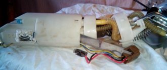
- And immediately purchase everything you need to carry out a full replacement, as shown in Photo No. 2.
Designations in the photo:
- 1 - oil pump
- 2—pan gasket
- 3 - pump gasket
- 4 - sealing ring
- 5 - sensor mounting bracket
Attention: The pumps of the VAZ 2108-1011010 and 2111, 2112-1011010 engines are almost the same, with the exception of point No. 5 - the sensor mounting bracket is different, do not miss this point!
Tip: It is recommended to install only a factory-produced gasket under the pump, since a non-standard gasket may have a thickness that does not meet the specifications and cause problems with the operation of the pump.
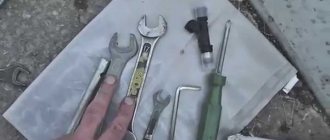
Necessary tool
- A set of wrenches (open-end - spanner preferably)
- Socket set and ratchet
- Two strong flathead screwdrivers
- Hexagon set
Why is an oil pump needed?
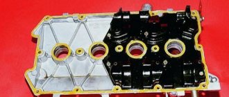
Pump appearance
The oil pump in the engine is designed to build up pressure in the oil system, for the necessary lubricating effect of all rubbing parts of the internal combustion engine. If the pressure in the system is insufficient, the lubrication effect will be ineffective, which in turn will lead to the engine being unsuitable for operation. In this case, the low oil pressure warning light on the instrument panel should light up. Therefore, you should not delay repairing the oil pump.
You are left with two options. Take the car to a service station and lose a lot of time and money, or change the oil pump yourself.
Pump diagnostics
Oil pump removed for diagnostics. Symptoms: oil leak.
Secondly, you need to check whether power is supplied to it correctly or whether a wire is broken somewhere. And only after these procedures, if the light does not go out, will you have to change the oil pump.
Why might it break prematurely?
An oil leak from the oil pump can lead to expensive engine repairs.
Replacement of the oil pump can also be caused by poor quality oil, which will lead to rapid clogging of the oil receiver grid and subsequent lack of oil pressure in the system. It is not uncommon for an oil pump to become wet and oil to leak from underneath it. In these cases, you can get by by replacing the gasket and cleaning the oil receiver mesh.
In general, the oil pump does not bring much trouble to VAZ-2112 owners. It is designed for 120 thousand kilometers. When purchasing a new pump and spare parts for its repair, choose original spare parts. The official manufacturer of oil pumps for the VAZ-2112 is the Tolyatti Plant (TZA).
Common unit breakdowns
- operational wear of the components of the unit: the pump housing or gears fail: during the operating cycle, the gap between the driven and driving gears increases. In normal condition it does not exceed 0.25 mm. Wear leads to the fact that the distance between the parts increases to 0.5 mm: the gears no longer mesh. The described breakdown makes the oil pump unsuitable for routine repairs - it is easier to buy a new part than to install new gears and adjust them;
- leakage: oil begins to leak from under the pump. The reason for this is a leaky oil pump gasket. Replacing the gasket solves the problem;
- Oil receiver clogged: The oil receiver becomes clogged due to a clogged crankcase. In this case, you need to dismantle the oil pan and clean the mechanism.
In most cases, it is necessary to purchase a new oil pump. The price of a new part in online stores is in the range of 1700 - 2500 rubles. The devices are compatible with the first generation Samara.
Signs and causes of oil pump malfunction Lada 2114
There are several markers, the appearance of which will allow you to suspect defects in the pump:
- The corresponding light on the dashboard lights up;
- Oil puddles regularly form under the car;
- Smoke is generated during engine operation.
Causes of unit malfunctions:
- use of motor oil that does not comply with the car manufacturer’s recommendations;
- oil filter clogged;
- permanently low level of lubricating fluid in the crankcase;
- non-working condition of oil level monitoring devices;
- failure of the engine lubrication system valve;
- impurities entering the engine oil (most often coolant is mixed with it).
All the described breakdowns are accompanied by activation of the control lamp, so do not delay repairs; begin service operations after activating the control indicator.
And here is another problem, the instrument panel of the VAZ 2110 presents a surprise: the oil pressure indicator lights up, and it has not gone out for a long time. The main cause of failure is the failure of the oil pump.
{advertising}
We will try to repair the oil pump ourselves, without any help from specialists.
In the case where there is a clear decrease in pressure in the engine, it is necessary to check the electrical circuit located from the sensor and extending all the way to the warning lamp on the dashboard. So, we take the wire from the sensor and press it against the 2110 motor, so we form a mass. If there is no damage to the circuit, the light will go out. Then we will need to unscrew the oil pressure sensor and check its condition: it should be in oil. A dry sensor indicates that the fault is located somewhere lower.
One of the most common malfunctions is a stuck oil filter valve. This point also needs to be kept in your head.
We went to the store and bought a good oil filter, and then proceeded to install it. When the installation was completed, the engine was started, but pressure still did not appear. I had to open the pan and check the oil receiver along with its rubber sealing rings. If everything is normal here, you need to disassemble the oil pump.
Specifically, in our case, the cause of the malfunction was a stuck pressure relief valve. We pulled out the stuck valve, used diamond lapping and worked on the oil pump housing. As a more preferable option, it is worth noting final grinding, since the oil pump housing is made of light alloy, so it grinds in quickly and easily. After carrying out the described procedures, you need to rinse the structure in gasoline and wipe thoroughly. Take the oil and apply it to the pressure relief valve. Now you can start assembling the VAZ 2110 engine. Turn the engine over in idle mode. This is done without spark plugs. After starting, the light should go out.
However, it is worth remembering that the cause of the breakdown may not only be the indicator and the oil pump. Serious engine problems can also cause significant problems. So if the described repair of the VAZ 2110 oil pump did not help get rid of the problem, you need to contact a service center and diagnose the engine.
Filming
- First you need to disconnect the negative cable from the battery.
- Draining the oil from the engine
- We take out the camshaft drive belt
- We take out the crankshaft toothed pulley, then its key, using two flat-head screwdrivers.
- Then remove the oil sump.
- Unscrew the oil intake mount.
- Using a 10mm socket with a ratchet and an extension, unscrew the six bolts securing the oil pump to the cylinder block.
- Remove the unit from the engine.
Be sure to wash the new oil pump with gasoline to remove grease for preservation. We fill it with oil before installation so that it does not rotate dry when starting. It is also important to turn the drive gear in order to place the pump on the crankshaft: so that the protrusions on the gear coincide with the groove on the crankshaft. Lubricate the seal lip with oil before putting the pump back. Carefully tuck the working edge of the oil seal onto the shaft journal using a wooden stick. Be careful and attentive when tightening the bolts so as not to strip the threads. Proceed in reverse order, install the remaining parts.
As can be seen from the above, this is not such a difficult job. The main thing for her is to approach it correctly and creatively. After all, proper lubrication is the basis for the longevity of a car.
Repair manual for VAZ 2110, 2112, 2111 (Lada 110)
1. Remove the oil pump from the vehicle (see “Removing and installing the oil pump”).
2. Unscrew bolt 1 of the fastening and remove crankshaft position sensor 2.
3. Remove the six bolts securing the pump cover.
Step-by-step instructions for repairing and inspecting oil pump parts:
1. For a detailed inspection, it is necessary to remove the oil pump.
2. First, you need to unscrew the bolt (1) and remove the crankshaft position sensor (2), which is only available on engines with a fuel injection mechanism.
3. When disassembling the pump, you need to unscrew the six bolts and remove the pump cover.
4. Using two screwdrivers, you need to lift the pump housing so that the pins on the housing can come out of the holes located in the cover of the VAZ 2110 oil pump. Now remove the housing itself by disconnecting it from the cover.
5. We take the gears out of the cover: first the driving one, and then the driven one.
6. Now you need to unscrew the pressure reducing valve plug. An O-ring must be installed under this plug. Inspect the ring - if it is too compressed, it needs to be replaced.
7. Having unscrewed the plug, we take out the spring of the pressure reducing valve.
8. Now we take out the valve itself, gently tapping the body on a clean wooden stand. If the valve does not come out, it must be removed using a thin pointed object, preferably also wooden, so as not to damage the surface.
9. Now you need to carefully inspect the aluminum cover for visible signs of wear, mechanical damage, deep scratches in the contact areas of the gears. If found, the cover must be replaced with a new one.
11. The size of the maximum permissible diameter of the driven gear socket is 75.1 mm, so we measure the diameter, and if it exceeds the permissible one, we will also have to replace the housing.
12. Now you need to measure the width of the body segment in the middle part. If the measured value is less than 3.4 mm, the VAZ 2110 pump housing must be replaced.
13. Check the gears. The thickness of the drive should not be less than 7.42 mm. We measure: if it is less, we replace the gear.
14. The same applies to the slave. If the thickness is less than 7.35 mm, the gear must be replaced.
15. Then we check the axial clearances of the gears. It is necessary to install the drive gear back into the housing, after which we apply a steel ruler to the housing and use a feeler gauge to measure the gap between the gear and the ruler.
16. In the same way, measure the axial clearance between the attached ruler and the driven gear. For the drive and driven gears, the maximum permissible axial clearance is 0.12 mm and 0.15 mm, respectively. In cases where these values are exceeded, the gears must be replaced with new ones.
17. Through calculation, more accurate values of axial clearances can be obtained. To do this, a micrometer is used to measure the thickness of the oil pump housing along the outer surfaces, as well as the thickness in the area of the sockets for the drive and driven gears along milled surfaces in several places. The axial clearance is calculated based on the difference between the arithmetic mean of the socket depth and the measured thickness of the gears.
18. The next stage of repair is to inspect the pressure reducing valve seat to detect rough scratches and other deep mechanical damage on the inner surface. If found, the cover must be replaced.
19. If burrs and deep mechanical scratches are detected on the pressure reducing valve itself, it must also be replaced with a new one.
20. We also replace a bent, broken/broken or cracked pressure relief valve spring. The height of the spring in its free state is normally 44.72 mm; the same parameter under a load of 4±0.24 kgf is 31.7 mm. If there is a discrepancy, the spring must be replaced.
21. Assembling the oil pump. We install the driven gear with the chamfers on the teeth towards the housing.
22. Then install the drive gear in the same way - with the chamfers on the teeth facing the body. The gears must be lubricated with engine oil before installation.
23. Now you need to install the cover on the body and tighten the fastening bolts.
24. Before installing the pressure reducing valve into the seat with the bottom down, it must be lubricated with engine oil. Then you need to install the spring and tighten the plug with the aluminum O-ring of the oil receiver tube, also pre-lubricated.
25. It is necessary to pour engine oil into the pump through the oil receiver tube.
26. At the end of the repair and complete assembly of the car’s oil pump, turn the gears several turns so that the working surfaces of the gears are well lubricated.
Oil pump replacement and repair
The oil pump of VAZ 2110–12 cars is replaced in an inspection pit or overpass. In extreme cases, you can use a jack. To work you will need the following tools:
- wheel wrench;
- keys for 10, 13, 17;
- hexagon socket wrenches 5 and 8;
- large slotted screwdriver;
- special key for tension rollers (to adjust the timing belt tension);
- clean, dry container to drain the oil.
Removing the oil pump
The procedure for dismantling the oil pump on a VAZ 2110–2112 is as follows:
- Remove the timing drive casing, having first unscrewed the mounting bolts on it with a 10mm wrench (on an eight-valve engine - 3 bolts, on a sixteen-valve engine - 6).
To remove the timing case, you need to unscrew 6 bolts
To loosen the alternator belt, you need to unscrew the bolt with a 13 mm wrench.
To remove the pulley, you need to unscrew the bolt with a 17 mm wrench
The marks on the camshaft gears must match the marks on the rear timing cover
Before removing the timing belt, make sure that the marks on the pulley and on the pump cover match
To loosen the timing belt, you need to unscrew the bolts securing the tension and guide rollers
When removing the crankshaft timing belt, be careful not to lose the key.
To make the oil drain faster, unscrew the filler neck.
To remove the pan, you need to unscrew the 16 bolts securing it with a 10mm wrench.
If the gasket is deformed or damaged, it must be replaced
The oil receiver is secured with three bolts to the main bearing cap and the oil pump.
To remove the oil pump, you need to unscrew 6 bolts with a 10mm wrench
When installing the oil pump, assembly is performed in reverse order.
Oil pump repair
Practice shows that in most cases it is better and easier to replace the pump as an assembly. If the device malfunction is not critical, you can try to repair it. Before this, the pump should be disassembled and the reason why it failed should be determined.
Pump disassembly
The procedure for disassembling the pump is as follows:
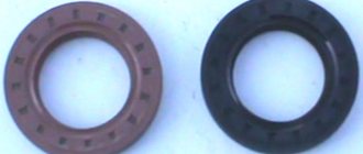
- Using thin pliers, remove the crankshaft oil seal from its seat. If it shows signs of damage, it will need to be replaced.
The crankshaft oil seal is removed using thin pliers
To disassemble the pump you will need a 5mm hex key.
The drive gear is located in the cover, and the driven gear is located in the housing
The valve plug is unscrewed with an 8mm hex key
The pressure reducing valve is pressed by a spring
Assessing the condition of oil pump elements
In order to understand whether the pump can be repaired, it is necessary to inspect all its elements and assess the degree of wear in the following order:
- Inspect the internal surfaces of the pump housing and cover. There should be no burrs, roughness or dents on them.
- Using a caliper, measure the diameter of the driven gear seat in the pump housing. It should not exceed 75.1 mm.
If the diameter of the seat is greater than 75.1 mm, the housing must be replaced
The segment thickness must be at least 3.4 mm
The thickness of the driven and driving gears should not be less than 7.42 and 7.45 mm
When free, the spring should have a length of 55.72 mm, when compressed - 31.7 mm
Engine diagram and structure
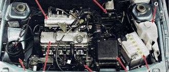
Many motorists know the structure of the main power unit, but not everyone remembers it. In order to understand how the process itself occurs, let us recall how the engine works.
Engine diagram
1 - channel in the cylinder block for supplying oil to the oil line of the cylinder head; 2 — channel in the cylinder head; 3 — pipe for exhausting crankcase gases into the air filter housing; 4 - oil filler cap; 5 — exhaust hose pipe; 6 — pipe for removing crankcase gases into the throttle space; 7 - oil line in the cylinder head; 8 - camshaft; 9 — oil supply channel to the camshaft bearing; 10 — oil pressure indicator sensor; 11 — pressure reducing valve; 12 — channel for supplying oil from the filter to the main oil line; 13 - oil pump drive gear; 14 — driven gear of the oil pump; 15 — oil supply channel from the pump to the filter; 16 — anti-drainage valve; 17 — cardboard filter element; 18 — oil sump; 19 — oil receiver; 20 - drain plug; 21 - bypass valve; 22 — oil filter; 23 — oil supply channel from the crankshaft main bearing to the connecting rod; 24 — oil supply channel to the crankshaft main bearing; 25 - main oil line
How does engine lubrication occur (diagram and explanation)
Engine lubricant circulation diagram
So, when the issue of engine design has been considered, we can proceed directly to the consideration of lubrication. The system itself is considered combined.
Using pressure, the following are lubricated: main and connecting rod bearings of the crankshaft, camshaft bearings, cylinder walls (using splashing), pistons and oil scraper rings, the camshaft itself, valves and pushers.
The oil pump is located inside the engine, and only the cover cap is visible from above. The oil pump drive is mechanical, forced.
Schematic representation of oil circulation
Replacing lubricant
In order to change the oil, you will need a tool, 5 liters of oil (about choosing oil here) and an oil filter.
Shel Helix oil recommended for filling into the 10 series Lada engine
So, let's look at the sequence of actions:
We remove the lower engine protection (if there is one, of course). Unscrew the oil pan drain plug.
We wait for the oil to drain. While the liquid is leaking out, it is necessary to replace the filter.
To do this, use a special tool to unscrew the filter element. You need to pour a little oil into the new filter and screw it in place of the old one.
It is worth noting that between the motor and the filter there is a copper o-ring, which also needs to be replaced.
We tighten the drain plug. Unscrew the filler plug.
Using a funnel, we pour new oil into the system until the fluid indicator on the dipstick is between the MIN and MAX indicators.
LUBRICATION SYSTEM
Rice.
2–69. Engine lubrication system: 1 – channel in the cylinder block for supplying oil to the oil line of the cylinder head; 2 – channel in the cylinder head; 3 – pipe for exhausting crankcase gases into the air filter housing; 4 – oil filler cap; 5 – exhaust hose pipe; 6 – pipe for removing crankcase gases into the throttle space of the carburetor; 7 – oil line in the cylinder head; 8 – camshaft; 9 – oil supply channel to the camshaft bearing; 10 – oil pressure warning lamp sensor; 11 – pressure reducing valve; 12 – channel for supplying oil from the filter to the main oil line; 13 – drive gear of the oil pump; 14 – driven gear of the oil pump; 15 – oil supply channel from the pump to the filter; 16 – anti-drainage valve; 17 – cardboard filter element; 18 – oil sump; 19 – oil receiver; 20 – drain plug; 21 – bypass valve; 22 – oil filter; 23 – oil supply channel from the crankshaft main bearing to the connecting rod; 24 – oil supply channel to the crankshaft main bearing; 25 – main oil line
The design of the lubrication system is shown in Fig. 2–69.
Combined lubrication system. The main and connecting rod bearings of the crankshaft and camshaft bearings are lubricated under pressure; splashing - cylinder walls, pistons with piston rings, camshaft cams, tappets and valve stems.
Rice. 2–70. Oil pump parts:
1 – pump housing; 2 – driven gear; 3 – drive gear;
4 – pressure reducing valve; 5 – pressure reducing valve spring; 6 – plug; 7 – sealing ring; 8 – front crankshaft oil seal; 9 – pump cover; 10 – rubber sealing ring; 11 – oil receiver
The oil pump (Fig. 2–70) is gear-type, with internal gears 2 and 3, located at the front end of the cylinder block. The oil pump drive gear 3 is mounted on two flats on the front end of the crankshaft. To reduce mechanical losses, the gears have trochoidal gearing. Oil receiver 19 (see Fig. 2–69) is bolted to the cover of the second main bearing and to the oil pump housing.
Oil filter 22 is full-flow, non-separable, with 21 bypass and 16 anti-drainage valves.
The oil must be changed when the engine is hot. To completely drain the oil, you must wait at least 10 minutes after opening the drain hole.
Rice. 2–15. Removing the oil filter using tool A.60312
When replacing the oil, you should also replace the oil filter, which is unscrewed using tool A.60312 (see Fig. 2–15). When installing, the filter is wrapped by hand.
Disassembly and assembly.
Carefully secure the oil pump in a vice so as not to damage cover 9 (see Fig. 2–70).
Unscrew the screws securing the pump housing 1 and cover 9, remove the housing, driven 2 and driven 3 gears. Unscrew plug 6 of pressure reducing valve 4 and remove spring 5 with valve.
Press out the self-clamping oil seal 8 of the crankshaft from the pump cover 9.
When assembling the pump, lubricate the outer diameter of the oil seal with engine oil and press it into cover 9 until it stops.
Carefully secure the cover in a vice, install the gears with chamfers on the tops of the teeth inside housing 1 and tighten the screws securing the housing and cover.
Insert the pressure reducing valve 4, the spring and tighten the valve plug, installing an aluminum sealing ring 7 with a thickness of (1.5 ± 0.2) mm under the plug.
Before assembling the pump, be sure to lubricate the drive and driven gears, the housing in the gear area, the rubber O-ring 10 of the oil receiver tube 11 and the pressure reducing valve with engine oil.
After assembling the pump, when turning the gears by hand, they should rotate smoothly, without jamming or jerking.
Checking the technical condition of parts.
After disassembling, wash all parts with detergents, blow with compressed air and check their condition.
Rice. 2–71. Mounting points for oil pump cover when milling planes:
1 – crankshaft oil seal; 2 – cover attachment points; 3 – pressure reducing valve plug.
X, Y – processed planes
The aluminum cover, when checking it in the contact area of the gears, should not have ledges, the surface of the cover should be flat. In case of noticeable wear, clamp the cover at points 2 (Fig. 2–71) and mill the X and Y surfaces to a size of (13.5 ± 0.3) mm. The maximum metal removal should not exceed 0.2 mm.
Replace the crankshaft oil seal 1 with a new one and press it in until it stops. When pressing the oil seal, the force should be applied as close as possible to the outer diameter of the oil seal.
Rice. 2–72. Limit wear of the oil pump housing
The working surfaces of the pump housing must not be scratched. The maximum size of the socket for the driven gear should not exceed 75.10 mm (Fig. 2–72). The minimum segment width must be at least 3.40 mm.
Rice. 2–73. Main Dimensions of New Oil Pump Parts
The main dimensions of the new pump parts are shown in Fig. 2–73.
Rice. 2–74. Measuring the axial clearances of the oil pump gears: 1 – drive gear;
2 – driven gear; S – axial clearance
Rice. 2–75. Limit wear of oil pump gears: a – drive gear;
b – driven gear
Measure the maximum axial clearances with an indicator (Fig. 2–74), which should not exceed 0.12 mm for the drive gear and 0.15 mm for the driven gear. If the clearances exceed the limits, replace the gears. The wear limits of gears are given in Fig. 2–75. If their dimensions exceed the limit values, also replace the gears.
Rice. 2–76. Basic data for checking the oil pump pressure relief valve spring
Rotary
The design of this type of unit is a little more complicated. The device consists of two rotors - driven and driven. Both are enclosed in a housing.
If the pump is unregulated, then the oil that is sucked into the device passes through the rotor blades. If the pressure level in the system is higher than the nominal or calculated pressure, then the pressure reducing valve is activated to relieve excess pressure.
Adjustable devices have a special movable stator equipped with a spring. It regulates and ensures constant oil pressure regardless of the engine speed. The stator is designed to control constant pressure by varying the volume of the cavity between the rotors. To do this, the stator is rotated in the required direction.
Removal
Begin:
- First of all, disconnect the “-“ (minus) wire from the battery, as with any other repair.
- Drain the oil (through the plug on the oil pan) from the engine
- We take out the camshaft drive belt
- We take out the crankshaft toothed pulley, then its key, using two flat-head screwdrivers.
- Now remove the oil pan
- Unscrew the oil intake fastener
Unscrew the oil intake fasteners and remove it
Using a 10mm socket with an extension and a ratchet, unscrew the six bolts securing the oil pump to the cylinder block.
Unscrew the mounting bolts using a ratchet socket
Remove the unit from the engine.
Be sure to wash the new oil pump with gasoline to wash off the preservation lubricant. We fill it with oil before installation so that it does not rotate dry when starting. It is also important to rotate the drive gear to install the pump on the crankshaft: so that the protrusions on the gear coincide with the groove on the crankshaft. Lubricate the edge of the oil seal before putting the pump back. Carefully tuck the working edge of the oil seal onto the shaft journal using a wooden stick. When tightening the bolts, be careful and careful. so as not to strip the thread. Install the remaining parts in reverse order.
Disassembly
So:
We clamp the pump body in a vice, placing soft pads on the jaws and, using a 8-mm hexagon, unscrew the bypass valve plug.
Unscrew the valve plug
- We remove the piston and spring of the bypass valve.
- We check the seat of the bypass valve - the presence of burrs and scratches is unacceptable
- Using a 5mm hexagon, unscrew the six bolts securing the pump housing to its cover.
Unscrew the bolts securing the housing to the cover
- We take out the pump housing.
- We take out its drive gear from the cover.
- Behind it, we remove the driven gear.
- We wash all pump parts with gasoline, diesel fuel or kerosene, wipe the gears dry, and lubricate them with clean oil before installing them back.
- We carefully inspect the body for cracks, chips, and severe burrs, and if found, replace it.
Permissible seat diameter and permissible partition thickness
- The same goes for pump gears; scuffing, chips, and cracks are not acceptable.
- We check the condition of the pressure reducing valve spring; if it is broken, cracked, or very short (compressed and does not match the dimensions), we replace it.
Acceptable dimensions of the pressure reducing valve spring
Assembly
We assemble the pump in the reverse order of disassembly. The driven gear inside the pump is positioned so that its side with chamfers and a mark is attached to the housing.
The mark with which the driven gear is applied to the housing
The same with the drive gear. That's all. The pump assembly is completed, all that remains is to install it in place, as our instructions say. In addition to the instructions, we recommend watching a video on this issue.
Max
The first problem we encountered after purchasing a used VAZ 2112 car was that the timing belt broke and all the valves were bent. The repair cost more than 15 thousand rubles. After buying a car, be sure to go to a car service center, check everything and repair it, otherwise the repair may cost a pretty penny like it did for me. And so the VAZ car is not whimsical in maintenance. I do everything myself and rarely call for service.
your name
Timing and alternator belts are usually changed immediately upon purchase. The same as liquids (antifreeze, brake fluid, oil).
VAZ 2109: oil pump and its malfunctions When you need to replace the oil pump in a VAZ 2104 Replacing the VAZ oil pump yourself Repair and replacement of the VAZ 2110 oil pump
Replacing the oil receiver of a VAZ 2112
In this article we will continue assembling VAZ-2112 engine components.
Lubricate the sealing ring of the oil receiver with engine oil
It is advisable to replace the oil receiver O-ring
We install the oil receiver in place and tighten the bolt securing the oil receiver to the oil pump with a torque of 7.0-8.0 Nm (0.7-0.8 kgf m).
We tighten the two bolts securing the oil receiver to the cover of the second main bearing with a torque of 8-10 Nm (0.8-1.0 kgf m)
Cut off the protruding ends of the oil seal holder gaskets.
Lubricate the plane of the cylinder block with grease
Installing the oil pan gasket
If the pan is slightly deformed, it is better to coat the pan gasket with sealant.
We tighten the oil sump mounting bolts with a torque of 5-8 Nm (0.5-0.8 kgf m).
Install the key into the groove of the crankshaft
Installing the crankshaft timing belt
We put the timing belt on the crankshaft pulley
Install the washer on the belt drive pulley
We put on the generator drive pulley and attach the bolt and washer
We tighten the pulley mounting bolt, holding the flywheel on the other side with a torque of 97.9 - 108.8 Nm (9.90 -11.1 kgf.m)
We install the sealing gasket on the water pump and lubricate the gasket with grease.
Install the water pump into the cylinder block so that the factory marking of the pump is directed towards the mating plane of the cylinder block, since the mounting bolts are located asymmetrically.
Tighten the coolant pump mounting bolts to a torque of 7.64–8.01 Nm (0.78–0.82 kgf.m)
After this, install the cylinder head as indicated in the article - “Removing and installing the cylinder head.”
Running in the engine after assembly
The repaired engine is subjected to bench testing (run-in) without load according to the following cycle: 750–800 min -1. 2 minutes
1000 min -1 . 3 min
1500 min -1 . 4 min
2000 min -1 . 5 minutes
After installing it on the stand and starting the engine, check:
– whether there is a leak of coolant or fuel between mating parts and in pipeline connections; – oil pressure and whether there is any oil leakage through the gaskets;
If any unusual knocking or malfunctions are detected, stop the engine, eliminate them, and then continue testing.
If oil leaks through the gasket between the crankcase and the cylinder block, tighten the fastening bolts to the recommended torque.
If the oil leak continues, check the gasket and replace it if necessary.
If oil leaks through the gasket between the cover and the cylinder head, check the gasket and rubber bushings on the studs securing the cylinder head cover.
If necessary, replace the gasket and bushings, following the recommendations outlined in the article “Engine Assembly”.
After engine repair, a certain period of running-in of the working surfaces of new parts is necessary.
This especially applies to those engines on which the pistons, connecting rod and main bearing shells have been replaced, the crankshaft journals have been ground, and the cylinders have been honed.
Therefore, when running in a repaired engine, do not subject it to maximum loads.
Engine break-in should continue with the vehicle at the recommended speeds for the vehicle's break-in period.
Engine lubrication system VAZ 2110
Introduction
In 1983, the design of a sedan based on the VAZ-2108 hatchback began. The project was named VAZ-2110. However, the designers made too many changes, including those that made the car more expensive. Therefore, in 1987, this project was separated from the project of simply turning the VAZ-2108 into a sedan (now called VAZ-21099).
The first prototype of the VAZ-2110 appeared in July 1989. The November 1990 issue of the magazine “Behind the Wheel” published spy photos of the pre-production model, taken at the Porsche test site.[1] Serial production of the VAZ-2110 was planned to begin in 1992, but due to the ensuing economic crisis, these plans were delayed by several years.
VAZ-2110 is a new generation front-wheel drive car with a sedan body produced by the Volzhsky Automobile Plant.
The first VAZ-2110 was produced on June 27, 1995 in the pilot production of AVTOVAZ, mass production began in 1996. By that time, technologies in the global automotive industry had reached a new level, and the breakthrough model for the late 80s could no longer be called absolute new. However, despite this, as well as the traditional quality claims for AVTOVAZ products, it still became a step forward for the domestic auto industry. Unlike the Lada and Samara, the VAZ-2110 was positioned as a higher-class car, quite modern and competitive both externally and internally. In particular, an electronic engine control system and a diagnostic unit (on-board computer) were installed on the car, it was possible to install power steering and electric windows, galvanized metal was used in body parts, a new body painting technology was used, etc. The appearance of the “ten” "marked a new stage in the development of the domestic automobile industry.
The closest foreign analogues of the “ten” are the first generation Opel Astra, Opel Kadett E, third and fourth generation Audi 80, Daewoo Nexia
Unlike previous models, the VAZ-2110 car contains new original developments: the use of galvanized metal for body parts that are most susceptible to corrosion, fastening the hood on gas struts, an adjustable steering column, an on-board control system, an immobilizer, a gasoline vapor recovery system, ventilated brake discs and a number of other innovations. It is possible to install an air conditioner, which is standard equipment on some of the machines. According to their price characteristics, the cars belong to the upper segment of the price range of VAZ cars.
The “Ten” was initially equipped only with short-stroke carburetor 1.5-liter 69-horsepower VAZ-21083 engines, which, combined with a high degree of unification in a number of components and assemblies (unfortunately, not all) with already produced cars, made it somewhat easier for the owners of the first “ dozen” of their operation and maintenance. Although there were quite a few problems with “original” and therefore scarce spare parts (for example, an expansion tank, front struts, etc.). But the performance characteristics: maximum speed of 162 km/h and average fuel consumption of 7.5 l/100 km are significantly improved (by 12%) compared to model 21099, mainly due to a decrease in the aerodynamic drag coefficient. Currently, the carburetor engine has given way under the hood to a new generation of engines with distributed fuel injection and electronic control.
The model with an 8-valve, 79-horsepower, 1.5-liter engine with distributed fuel injection has the VAZ 21102 index. This engine provides sufficient power (56 kW) and torque (118 Nm), with moderate fuel consumption. The maximum speed of such a car reaches 170 km/h, and acceleration to “hundreds” takes 14 seconds. Cars with such an engine, due to its high elasticity and torque, are especially good when traveling in heavy city traffic.
For more active drivers, a 16-valve version with a 1.5-liter gasoline engine was developed based on this engine. with a power of 94 hp, with a twin-shaft cylinder head, providing increased power (69 kW) and torque (130 Nm), allowing the car to have improved dynamic qualities. A car equipped with such an engine has the VAZ 21103 index, the maximum speed is already 185 km/h, and acceleration to “hundreds” takes only 12.5 seconds. These modifications are becoming more and more common on the roads, and the 2-liter 150-horsepower versions of the VAZ-21106 STi are quite economical, expressive and expensive. Of course, because the Opel X20XEV engine with a twin-shaft 16-valve cylinder head and a point injection system allows it to accelerate to 205 km/h. With it, the hundred-kilometer barrier is overcome in just 9.5 seconds. There is also a combat 240-horsepower (!) VAZ-21107 “Rally” 2.0 V16 with a special tubular safety cage built into the body. Its maximum speed is 220 km/h, and the acceleration time to 100 km/h takes only 7 seconds! But they make it individually, only according to the orders of athletes, and it costs the same as foreign rally cars: expensive (22 thousand dollars). It must be said that some domestic tuning companies create (even without the use of expensive imported components) quite successful speed or, on the contrary, comfortable versions of the “ten”, dynamics, the handling of which when driving is significantly improved. There are also all-wheel drive versions of the “ten” with a sporty or all-terrain orientation, but they are either experimental or small-scale, and therefore expensive.
Modern interior design (which is still not as neat as its foreign counterparts), good aerodynamics, a spacious luggage compartment (480 l) with wide transformation capabilities (a hatch in the rear seat and a trunk lid that reaches the bumper allow you to transport long cargo), high degree of maintainability - all this is in favor of the VAZ-2110.
The front-wheel drive “tenth” family from Tolyatti, designed from scratch, is, of course, a new word in the domestic automotive industry. Compared to previous VAZ models, the softness, smoothness and stability of the ride has increased (for which we had to pay for more “woofiness” in the steering, which, however, is acceptable for the higher class, which included the “ten”). Improved efficiency. But at the same time - lack of options, incompleteness, low-quality components. There is still a long way to go to reach the “world level”! In addition, due to the “soft” suspension and 13-inch wheels, the car constantly touches the road with insufficiently strong factory protection for the engine sump. Everything indicates that the ideal balance between ride comfort and handling for a domestic car has not yet been found.
The 2002 model range of AVTOVAZ JSC includes modifications of the VAZ-21102 and VAZ-21103. The following versions are available - “standard” (VAZ-21102-00), “norm” (VAZ-21102-01 and VAZ-21103-01) and “luxury” (VAZ-21102-02 and VAZ-21103-02).
Distinctive features: modern design and interior of the car, improved performance characteristics of the VAZ-2110 that meet the new increased requirements of the automotive market. In addition to the standard, the “norm” equipment includes electric windows, body paint with metallic enamels, velor upholstery of seats and doors, and headrests in the rear seat. Cars in the “luxury” configuration are additionally equipped with 14-inch alloy wheels, an on-board computer, a heated front seat system, electrically adjustable and heated exterior rear-view mirrors, and fog lights.
In addition to the main mass-produced models, small-scale models are produced: the “charged” sedan VAZ 21106, the stretch sedan 21108 Premier, the limousine 21109 Consul. VAZ subsidiaries also offer various modifications, for example, the Bronto company produces armored modifications of the sedan and stretch. The 21106K coupe and all-wheel drive 4x4 station wagons VAZ 2111x Lada Tarzan 2 are produced in single copies. Tuning companies offer original sets of attachments for body tuning: Lada-Lady, Nika, Courage, Tornado, Sprint, Lada BIS.
The immediate prospects for the “tenth” family include updating the appearance (restyling). Thus, OPP VAZ is already producing modernized sedans under the symbols: 2110M and 2110T.
Classification and general structure of the car. Passenger cars are classified by engine cylinder displacement (displacement). Extra small class - up to 1.2 l, small class - 1.8 l, medium class - over 1.8 to 3.5 l, large class - over 3.5 l. In accordance with this classification, each new model is currently assigned a four-digit numeric index, in which the first two digits indicate the class, and the subsequent ones indicate its model. Model modifications have a fifth digit—the serial number of the modification. The letter designation of the manufacturer is placed next to the digital index. The first two digits indicate: 11—extra small class, 21—small class, 31—middle class, 41—large class. A passenger car consists of: 1. Body 2. Chassis 3. Engine The engine is a unit that converts thermal energy obtained from fuel combustion into mechanical energy used to move the car. The engine is located in the front of the car, but can also be located in the rear (ZAZ cars and others). The chassis includes the mechanisms that provide movement and control of the vehicle, and consists of a transmission, chassis and control mechanisms. The transmission changes the magnitude and direction of torque and transmits it from the engine to the drive wheels of the car; it consists of a clutch, gearbox, cardan shaft, final drive, differential and axle shafts. The cardan transmission is used to transmit torque from the gearbox to the drive axle. The chassis of a passenger car includes a subframe, structurally combined with the base of the body, front/rear axle beams, front and rear suspensions and wheels. Control mechanisms include steering, necessary to change the direction of movement of the car, systems that slow down the car, emergency stop and hold it stationary. The clutch serves to separate the engine and transmission during gear changes and smoothly connects the engine to the transmission without allowing a sudden increase in load, which ensures that the vehicle starts and stops smoothly without stopping the engine. The body of a passenger car is designed to accommodate the workplace of the driver, passengers and luggage. Most cars have a monocoque body to which all the components and mechanisms of the vehicle are attached. Engine VAZ 2110.
Lubrication system of the VAZ 2110. Engine lubrication is combined. The main and connecting rod bearings and the support-camshaft journal pairs are lubricated under pressure. Oil is sprayed onto the cylinder walls (further to the piston rings and pins), to the camshaft cam-pushrod pair and to the valve stems. The remaining components are lubricated by gravity. The oil pump is gear-type, with internal gears, and a pressure reducing valve. Mounted on the front wall of the cylinder block (from the crankshaft side). The drive gear (smaller diameter) is mounted on two flats on the front end of the crankshaft. The maximum diameter of the socket for the driven (large) gear when worn should not exceed 75.10 mm, the minimum width of the segment on the body separating the drive and driven gears is -3.40 mm. The axial clearance should not exceed 0.12 mm for the drive gear and 0.15 mm for the driven gear. The oil receiver is bolted to the second main bearing cap and pump housing. The oil filter is full-flow, non-separable, with bypass and anti-drainage valves. On the inner surface of the bushings there are grooves resembling threads for lubrication: for the intake valve bushings - for the entire length, for the exhaust valves - up to half the length of the hole
Engine VAZ 2110.
(longitudinal section) 1 — generator drive pulley (damper); 2 - oil pump; 3 — toothed pulley of the coolant pump; 4 — connecting rod; 5 — piston pin; 6 — tension roller; 7 — camshaft toothed pulley; 8 — front cover of the timing mechanism drive; 9 — timing belt; 10 — rear cover of the camshaft drive; 11 — camshaft oil seal; 12 — cylinder head cover; 13 - camshaft; 14 — front cover of camshaft bearings; 15 — oil separator mesh for the crankcase ventilation system; 16 — rear cover of camshaft bearings; 17- oil filler cap; 18 — fuel pump; 19 — ignition distributor; 20 — housing of auxiliary units; 21 — outlet pipe of the cooling jacket; 22 — pusher; 23 — valve spring; 24 — coolant temperature sensor; 25 - valve; 26 — cylinder head; 27 — cylinder block; 28 - piston; 29 — flywheel; 30 — crankshaft rear oil seal holder; 31 — rear crankshaft oil seal; 32 - crankshaft; 33 — main bearing cover; 34 — oil pan; 35 — oil pump receiver; 36 — connecting rod cover; 37 — front crankshaft oil seal; 38 — crankshaft toothed pulley; 39 — oil pan drain plug; 40 - oil filter; 41 — coolant pump; 42 — exhaust manifold; 43 — intake manifold; 44 — carburetor; 45 — valve adjusting washer; 46 — crankcase ventilation hose; 47 — valve block; 48 — valve guide; 49 - oil dipstick. Gasoline, four-stroke, four-cylinder, in-line, transverse, eight-valve, overhead camshaft. The power supply system is carburetor. The cylinder operating order is 1-3-4-2, counting from the crankshaft pulley. On the right side of the engine (along the direction of the car) are located: the drives of the camshaft and coolant pump (by a toothed belt) and the generator (by a V-ribbed belt). On the left are located: ignition distributor sensor (distributor), thermostat, coolant temperature sensor, starter (on the clutch housing). Front: spark plugs and high voltage wires, oil dipstick, crankcase ventilation hose, generator (lower right). Rear: intake and exhaust manifolds, oil filter, oil pressure sensor, as well as fuel pump, carburetor and air filter housing (at the top). The model 2110 engine replaced the 21083-80 engine, which was installed on the VAZ-2110-011 and VAZ-21111-011 cars. 0t engine 21083-80 model 2110 is distinguished by a camshaft 2110, which provides the specified engine power when running on AI-91 gasoline. Currently, the 21083-80 engine is not produced. Based on the 2110 engine, the 2111 model was created.
Device Features
The design of the lubrication system is shown in Fig. 2-69.
Rice. 2-69. Engine lubrication system: 1 - channel in the cylinder block for supplying oil to the oil line of the cylinder head; 2 — channel in the cylinder head; 3 — pipe for exhausting crankcase gases into the air filter housing; 4 - oil filler cap; 5 — exhaust hose pipe; 6 — pipe for removing crankcase gases into the throttle space of the carburetor; 7 - oil line in the cylinder head; 8 - camshaft; 9 — oil supply channel to the camshaft bearing; 10 — oil pressure indicator sensor; 11 — pressure reducing valve; 12 — channel for supplying oil from the filter to the main oil line; 13 - oil pump drive gear; 14 — driven gear of the oil pump; 15 — oil supply channel from the pump to the filter; 16 — anti-drainage valve; 17 — cardboard filter element; 18 — oil sump; 19 — oil receiver; 20 - drain plug; 21 - bypass valve; 22 — oil filter; 23 — oil supply channel from the crankshaft main bearing to the connecting rod; 24 — oil supply channel to the crankshaft main bearing; 25 - main oil line
Combined lubrication system. The main and connecting rod bearings of the crankshaft and camshaft bearings are lubricated under pressure; splashing - cylinder walls, pistons with piston rings, camshaft cams, tappets and valve stems. The oil pump (Fig. 2-70) is gear-type, with internal gears 2 and 3, located at the front end of the cylinder block. The oil pump drive gear 2 is mounted on two flats on the front end of the crankshaft. To reduce mechanical losses, the gears have trochoidal gearing. Oil receiver 19 (see Fig. 2-69) is bolted to the second main bearing cover and to the oil pump housing. Oil filter 22 is full-flow, non-separable, with 21 bypass and 16 anti-drainage valves.
Change of oil
The oil must be changed when the engine is hot. To completely drain the oil, you must wait at least 10 minutes after opening the drain hole. When replacing the oil, you should also replace the oil filter, which is unscrewed using tool A.60312 (Fig. 2-15). When installing the filter, wrap it by hand.
Rice. 2-15. Removing the oil filter using tool A.60312
Oil pump installation
- 1. Before installing a newly purchased VAZ 2112 or 2110 oil pump, be sure to lubricate its pressure reducing valve and gears. Also, when replacing, use only a new oil seal;
- 2. Install the oil pump, place the timing belt on the tension rollers, and align it according to the marks. Next, the plastic protection is installed.;
- 3. Put on the wheel;
- 4. Install the oil intake on the oil pump VAZ 2112, 2110;
- 5. Thoroughly degrease the crankcase and apply sealant;
- 6. Install a new gasket, then apply sealant again;
- 7. Degrease the block, install the crankcase in its place. The task will be simplified if you first screw a few bolts in different places and then tighten the rest;
- 8. The flywheel protection is installed, followed by the crankcase protection (if available);
- 9. Fill with high-quality oil and start the VAZ 2110, 2112 engine.
Repair of pump VAZ 2112, other models
You can also repair the VAZ 2110 oil pump with your own hands, which consists of disassembling this product, visual inspection to identify worn parts, followed by replacement. But it is the best option only if there are spare parts or another serviceable unit. In all other situations, it would be more practical to purchase a new product for the VAZ 2110, 2112.
Replacing the oil pump
Replacing the oil pump of a VAZ 2110 is done quite quickly and does not require significant special knowledge, and therefore is feasible for most drivers:
If necessary, replacing the VAZ 2110 oil pump is done quickly enough and does not require significant special knowledge, and therefore is feasible for most drivers:
- 1. Drain the oil - it is more practical to perform this procedure on a warm engine. Place a container (of sufficient volume), unscrew the drain neck and wait until it drains completely;
- 2. Unscrew the 3 bolts of the protection that covers the flywheel near the crankcase. Remove protection;
- 3. Unscrew the crankcase bolts and remove it. After this, the pump becomes visually visible;
- 4. Unscrew the oil intake (3 bolts) from the oil pump.
Removing the oil intake
- 5. All further work is performed in the engine compartment. Why does it need to be opened?
- 6. Remove the plastic timing belt protection.
- 7. Remove the right wheel, unscrew the washer securing the pulley. Remove the pulley itself;
- 8. Remove the timing belt.
 Next, unscrew the 6 bolts (using a wrench to secure the oil pump.
Removing the oil intake
Oil pump VAZ 2110, another model removed.
DIY pump repair VAZ 2110/2112
The driver does not always have the opportunity to replace a faulty pump. In some cases, it is possible to repair the device by restoring the operating functions of the pump. If the pump has not yet exhausted its service life (50 thousand kilometers), then you can repair it. However, the pump cannot be repaired without using a special repair kit. This is a set of rubber gaskets and parts that most often fail and need to be replaced.
Repair kits for pumps may vary in composition, depending on which spare parts need to be replaced
In addition, you will have to thoroughly prepare for repairs: the place for disassembling and repairing the pump must be clean and level.
How to disassemble a water pump
Once the pump is removed from the machine, it will need to be disassembled. Only after disassembly and thorough cleaning will it be possible to replace the leaked parts of the pump.
To disassemble the pump, it is recommended to follow the following diagram:
- Wipe the product with a dry cloth.
- Unscrew the pump pulley.
- Pull out the thrust ring.
- Use a hammer to knock out the bearings from the shaft.
- Pull the shaft itself out of the housing.
- Unfasten the impeller.
- If something remains from the oil seal, then remove the remaining rubber from the housing.
The procedure for disassembling the water pump is intuitive: until you remove the pulley, it is impossible to get to the shaft and impeller
After this, the cavity of the pump itself must be thoroughly cleaned of dirt and old deposits - you can wash the pump with the same gasoline that is usually filled into the VAZ 2110/2112 tank.
Oil pump VAZ 2112
Engine oil pump, a device necessary for injecting oil from a running engine, which is under pressure to the moving surfaces of the engine mechanisms. It is designed to increase the pressure in the internal system of the engine, and is thus used to provide lubrication to all operating parts of the internal combustion engine.
Malfunctions
Most often, the pump of the VAZ 2112 and other VAZ models with front-wheel drive leaks through the seal, which has to be changed.
The oil receiver also often fails, especially if you use low-quality oil, or missed replacing it in a timely manner, or the oil does not meet specifications (too thick).
Too liquid simply will not be pumped and the pressure sensor will immediately light up.
In this case, the oil receiver mesh becomes clogged, the circulation of oil through the engine becomes difficult, causes oil starvation, and as a result, the service life of the engine is significantly reduced.
This includes a malfunction of the pressure reducing (bypass) valve: either it is stuck in the open position, and then the oil pressure drops. Either it does not bypass, and then the oil will squeeze out through the oil seal
Replacement
The order of dismantling work:
First of all, it is necessary to drain the oil from the engine crankcase;
After all the oil has drained onto the pan, you need to remove this very pan;
Remove the oil sump;
Then you need to unscrew the oil receiver mounting bolts;
Now you can remove the oil receiver itself;
Remove the sealing gasket of the oil receiver;
Remove the camshaft drive belt;
Remove the crankshaft pulley;
Unscrew the bolts and remove the oil pump together with the sealing gasket;
First you need to thoroughly clean the oil receiver mesh from dirt, and then rinse it with white spirit. If the mesh cannot be cleaned or damage is visible on it, then it is necessary to replace the oil receiver itself. Our industrial portal provides the opportunity to all registered customers to purchase or order any vehicle part from a special catalog from manufacturers;
 Next, unscrew the 6 bolts (using a wrench to secure the oil pump.