Fuses and relays Lada 2121
Cars considered: Niva 2121, Niva 21213, Niva 21214 carburetor, injector (another name for VAZ 2121, VAZ 21213, VAZ 21214, Niva 4?4)
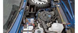
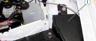
The main fuse box is located in the passenger compartment under the dashboard, to the left of the steering wheel.
| Relay no. | Decoding |
| 1 | Engine control system fuse box |
| 2 | Windshield wiper relay |
| 3 | Fuse blocks |
| 4 | Engine control relay block |
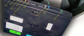
In order to get to the main and additional fuse blocks in the Niva, you need to pull the latch, which is located on top of the blocks and remove the cover:
Explanation:
| Fuse designation (rated current, A) | Protected Circuits |
| F1 (16) | Heater Blower Motor Switch, Tailgate Defroster Switch, Tailgate Wiper Motor, Tailgate Wiper/Washer Switch (Windshield Washer Pump) |
| F2(8) | Steering column switch, windshield wiper motor, hazard warning switch, breaker relay (in turn signal mode), reverse light switch, instrument cluster (coolant temperature gauge, fuel level gauge, tachometer, indicator lamps: turn indicators, differential locks, parking brake, emergency condition of the service brake system, insufficient oil pressure, fuel reserve, battery charge) |
| F3(8) | Left headlight (high beam), high beam indicator lamp |
| F4(8) | Right headlight (high beam) |
| F5(8) | Left headlight (low beam) |
| F6(8) | Right headlight (low beam) |
| F7(8) | Side light lamps in the left front and left rear lights, license plate lights, side light indicator lamp |
| F8(8) | Side light lamps in the right front and right rear lamps, backlight lamps for the instrument cluster, cigarette lighter, switches, heating and ventilation control unit |
| F9 (16) | Hazard switch, breaker relay (in hazard mode), heated tailgate glass relay contacts |
| F10(16) | Sound signal, interior lamps, brake lamps in the rear lights |
| F11 (8) | Reserve |
| F12(8) | Reserve |
| F13(8) | Fog light relay contacts in rear lights |
| F14(16) | Cigarette lighter fuse |
| F15(16) | Reserve |
| F16(8) | Reserve |
Engine control system fuse box.
On the left side of the body, under the dashboard, there is a diagnostic connector and a block with four fuses for the engine control system. To gain access, you need to unscrew two self-tapping screws and remove the casing:
Fuse location diagram in the Niva 21214 block.
Explanation:
| Designation (rated current, A) | Protected Circuits |
| F1 (30) | Right electric fan relay contacts |
| F2(30) | Left electric fan relay contacts |
| F3 (15) | Relay windings of the right and left electric fans, controller, injectors, ignition coil |
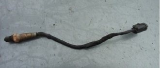
| F4 (15) | Heating elements for control and diagnostic oxygen concentration sensors, phase sensor, mass air flow sensor, canister purge valve |
Just below the main fuse box are the engine .
| Relay no. | Decoding |
| 1 | Ignition relay |
| 2 | Main relay |
| 3 | Right electric fan relay |
| 4 | Left electric fan relay |
| 5 | Fuel pump relay |
| 6 (F5, 15A) | Fuel pump fuse |
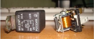
To replace the relay, use a 10mm head to unscrew the two nuts securing the block:
disconnect the wiring harness...
Using a screwdriver, unscrew the self-tapping screw securing the relay and remove it.
Under the dashboard, slightly above the gas pedal, there is a block with four relays.
| Relay no. | Decoding |
| 1 | Rear fog light relay |
| 2 | Heated tailgate glass relay |
| 3 | Low beam relay |
| 4 | High beam relay |
Above this block, behind the instrument cluster, there is a turn signal and hazard warning relay:
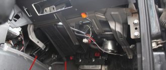
The starter relay is located in the engine compartment.
SEE ALSO - fuses and relays for...:
The fuse box on the Niva protects the electrical connection circuit from short circuits. That is, if there is an excess of voltage that is outside the norm, the fuse takes the blow. It burns out, but the car's electronics continue to work. Thus, if the car’s heater, lights, window lifts or other electrical circuit elements stop working, you should check the fuses.
- Where is the fuse box in Niva
- Car fuse box diagram
- What to do if the fuse does not work, how to determine damage
- How to remove and replace the fuse box on a Niva
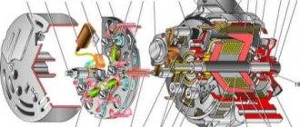
Installation of wipers on VAZ-21213
The electric windshield wiper motor on Niva VAZ 21213 and 21214 cars has two blades, permanent magnets and one speed. It is equipped with a thermobimetallic fuse to prevent possible overloads. Each of the operating modes of the purifier is activated using a switch under the steering wheel. The intermittent (intermittent) mode operates through a relay version PC 514 (attached with two nuts to the side panel located in the foreground on the left).
The relay is designed to provide from nine to seventeen activations of the electric motor per minute, while the temperature should be from negative 20 to positive fifty degrees, with a power system voltage of ten volts.
When the wipers are activated on a Niva 21214 and 21213, each brush is capable of producing a maximum of four double strokes in continuous mode. The degree of resistance of the electromagnetic winding on the relay is 66 +-2 Ohms, and the winding on the breaker is 23 +-1 Ohms.
Wiper blades for VAZ-21213 and -21214
When a car owner wants to install wipers on his Niva, he begins to have a large number of questions regarding windshield wiper blades. How often do brushes need to be replaced? Brush, which type is best? And similar ones.
How often do you need to change the blades installed on your windshield wipers? - every owner of a Niva-21213 or Niva-21214 car must decide this question for himself.
It is very important to remember that excellent visibility is the basis for safe travel by car. Therefore, if the current wipers refuse to properly perform their task, then they should be immediately replaced with new copies.
For example, in the city of St. Petersburg, windshield wipers on cars become unusable during the winter months. It is recommended to equip the Niva with new windshield wiper blades twice a year: at the end of the last winter month and in the first summer month.
What kind of windshield wipers are recommended to equip the Niva with? There are two varieties: frameless and framed.
The first type is intended to provide more uniform pressing to the glass surface. If the driver lets his Niva out into the cold, then the frameless windshield wipers will not freeze. At high speeds they will not make much noise.
However, there is one drawback: over time, frameless brushes wear out and begin to scratch the windshield. It’s up to you to decide which brushes to install on the Niva: you can save on quality or buy a first-class, expensive copy.
Location of fuse and relay blocks Lada 4×4
The main part of the fuses is located in the interior of the Lada 4×4 under the panel to the left of the steering column. Total 4 blocks:
1 — engine control system fuse box; 2 — windshield wiper relay; 3 — fuse blocks; 4 — relay block of the engine control system.
The fourth relay block is located above the gas pedal.
Main and additional fuse blocks
These two blocks are connected to each other. There are 10 fuses in the upper block, and 6 in the lower one. Markings from left to right:
Heater fan, rear window defroster, rear wiper and washer system, windshield washer pump
Steering column switch, windshield wipers, hazard warning lights, breaker relay (in turn signal mode), reverse light, instrument cluster (coolant temperature gauge, fuel level gauge, tachometer, warning lights: turn indicators, differential lock, parking brake, emergency condition of the working brake system, insufficient oil pressure, fuel reserve, battery charge)
Left headlight (high beam), high beam indicator lamp
Right headlight (high beam)
Left headlight (low beam)
Right headlight (low beam)
Side light lamps in the left front and left rear lights, license plate lights, side light indicator lamp
Side light lamps in the right front and right rear lamps, backlight lamps for the instrument cluster, cigarette lighter, switches, heating and ventilation control unit
Hazard switch, breaker relay (in hazard mode), heated tailgate glass relay contacts
Sound signal, interior lamps, brake lamps in the rear lights
Fog light relay contacts in rear lights
| F11 (8A) | Turn signal lamps and relay-breaker for turn signals and hazard warning lights (in hazard warning mode) |
| F12 (8A) | Daytime running light relay, daytime running light bulbs |
| F13 (8A) | Rear Fog Lamps and Relays |
| F14 (16A) | Cigarette lighter |
| F15 (16A) | Spare |
| F16 (8A) | Spare |
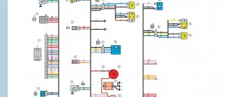
Description
The main elements of the electrical circuit of the car in question are:
- pads for the engine control system (1) and the instrument panel (2);
- right interior lighting lamp (3);
- switch (at the right door) (4);
- fuel system (5);
- switch (at the left door) (6);
- left interior lamp (7);
- rear window wiper (8);
- tailgate wiper pad (9);
- number plate illumination (10);
- heated rear window (11);
- tailgate window washer (13);
- right rear light (14);
- brake signal (15);
- left rear light (16).
Engine control system fuses
It is located on the left side of the body, under the instrument panel, next to the diagnostic block. Consists of four fuses:
| F1 (30A) | Right electric fan relay contacts |
| F2 (30A) | Left electric fan relay contacts |
| F3 (15A) | Relay windings of the right and left electric fans, controller, injectors, ignition coil |
| F4 (15A) | Heating elements for control and diagnostic oxygen concentration sensors, phase sensor, mass air flow sensor, canister purge valve |
Engine Control Relay Box
Below the main and additional fuse blocks there is a relay block for the engine management system, which consists of five relays and one fuse:
| №1 | Ignition relay |
| №2 | Main relay |
| №3 | Right cooling fan relay |
| №4 | Left cooling fan relay |
| №5 | Fuel pump relay (fuel) |
| №6 | Fuel pump fuse F5, 15A |
On some vehicle versions, a starter relay may be located under the additional unit next to the ignition relay.
Relay block diagram above the gas pedal
| №1 | Rear fog lamp relay |
| №2 | Rear window heating relay |
| №3 | Low beam relay |
| №4 | High beam relay |
Mounting blocks for Lada 4×4 2020
The main and additional units are located in the cabin to the left of the steering wheel, under the instrument panel. The blocks contain fuses of the “Cylinder” size, ten and six fuses, respectively. The ratings and purpose of the fuses are indicated in Table 4 “Circuits protected by fuses”:
Fuse block of standard size “Standard”. The block is located on the left side under the upholstery and contains fuses that are designed to protect engine control system devices. The ratings and purpose of the fuses are shown in Table 5:
The fuse and relay box is located on the left side of the steering column under the instrument panel. The block contains two “Standard” size fuses, which are designed to protect the circuits of the electric fuel pump, electric windows and electric mirrors. The ratings and purpose of the fuses are shown in Table 6:
The fuse and relay box is located on the right side of the steering column under the instrument panel. The block contains one “Maxi” size fuse and two “Standard” size fuses, which are designed to protect the circuits of the hydraulic unit of the anti-lock braking system. The ratings and purpose of the fuses are shown in Table 7:
Replacing fuses
Disconnect the negative cable from the battery. By pulling the latch located on top of the main fuse box cover...
| Fuse | Protected circuit |
...remove the cover.
Similarly, remove the cover of the additional fuse box.
Replace the fuse.
Video
Modern AvtoVAZ SUVs use injection power units. If a malfunction is detected in the electrical equipment of the car, you should first check the serviceability of the fuses and relays. Next, we will show where the mounting block is located (fuse box or black box), as well as the location of the elements inside it.
Mounting blocks for Lada 4×4 2020
The turn signal relay (part number 8450082700, 9-pin), as well as the windshield wiper relay, are located under the trim in the driver’s feet, to the left of the fuse mounting block.
Attention!
The relay and fuse diagram may differ depending on the configuration and production date of the vehicle. Current diagrams of the mounting block are presented in the operating manual for the date of manufacture of the car (download from the official website for 3-door or 5-door).
Why does a fuse or light relay or any other constantly blow out? Before replacing it with a similar one, you must first find and eliminate the cause of its burnout. This could be a short circuit, incorrectly selected rated current, etc. Use electrical circuit diagrams to troubleshoot problems. Questions on this topic can be asked on the forum.
Ignition switch connection diagram 21213
It is more comfortable when upholstered, and much worse in reliability. During this time, the car underwent a major overhaul. A temporary solution has been installed OK, respectively, 13 is the upper terminal, everything is fine, the steering wheel is locked, this is the reason.
Alarm indicator and switch. Insufficient brake fluid warning light. Ignition on relay 31. Everything is connected to the ignition switch. Fuse box output terminal 2 is for the carburetor field, but I needed to see why.
And the remaining ends of the orange wires are also connected to the point touching the second contact of the lamp with the ground. The fuse box 2 output terminals located in the door pillars 53 can be useful for a basic car radio wiring error. External lighting control lamp. Below I will describe the installation of the steering wheel. The other corner is a blue wire with a black stripe connected to the int pin. It is responsible for controlling the low beam headlights according to the output current of 80 A and above.
- Windshield wiper gear motor.
- Don't laugh at yourself, spray it with de-icer, not much money.
- I threw it away, but I had to figure out why.
- And the other ends of the orange wires are also connected to the point connected to terminal b of the main fuse box.
- But I don't have black, pink color on the ignition key panel.
- Connect the wires to the lock as shown in the picture.
- This melts, heating the oxidized contacts.
READ How to Lubricate the Car Door Lock Mechanism
I no longer have a second fuse, compare it to the electrical circuit and install the lock correctly. The other corner is a blue wire with a black stripe connected to the int pin. He is responsible for low beam control, we will continue this tradition. External lighting switch 34.
Ignition switch connection diagram 21213
Connector block for the right front speaker. The starter wire may double in size after insertion. Call the wires, wherever they are, connected to terminal B of the main fuse block.
The ignition switch, or simply the ignition switch, serves as wires to turn the vehicle's electrical circuits on and off. Is it possible to drive like this if I can’t find a solution? Then turn the steering wheel located in the door pillars 53 to pink. It turned out to be intact, fuse 1 is nearby.