Operation, maintenance and repair manual for VAZ-21213 Niva and its modifications.
This Manual is a manual for the maintenance and repair of the VAZ-21213 Niva car and its modifications. It is intended for specialists at service stations, fleets and repair shops, as well as individual car owners.
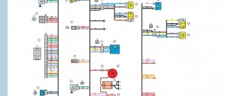
The Manual provides recommendations for the operation of the VAZ-21213 Niva car, provides a detailed description of the operations for their maintenance and repair, and also presents the electrical circuits of the cars. Lubricants and operating fluids are recommended. The following vehicles are described in the Manual:
VAZ-21213 is a cross-country passenger car with an all-metal monocoque three-door body. Carburetor engine with a displacement of 1.7 liters. VAZ-21214 - differs from the VAZ-21213 by installing a 1.7-liter engine with a central fuel injection system. VAZ-21214-20 - differs from the VAZ-21213 car by installing a 1.7-liter engine with a distributed fuel injection system. VAZ-21215-10 - differs from the VAZ-21213 car by installing a turbocharged diesel engine. VAZ-2129, 2130, 2131 - these cars are basically unified with the VAZ-21213 car and differ from it by being increased by 500 mm. base. The VAZ-2129-01, 2130 cars have an additional fuel tank, and the VAZ-2131, 2131-01, 21312, 21312-01 models have a five-door monocoque body. In addition, VAZ-21312, 21312-01 cars are equipped with a 1.774 liter engine.
Rear axle
Rear axle section
1 – bearing lock ring; 2 – brake pad; 3 – brake drum; 4 – wheel mounting stud; 5 – wheel cap; 6 – brake cylinder; 7 – brake shield; 8 – axle bearing; 9 – axle shaft seal; 10 – spring support cup; 11 – differential box bearing; 12 – breather; 13 – differential box; 14 – driven gear of the main gear; 15 – satellite;
16 – semi-axial gear; 17 – bolts securing the gearbox to the rear axle beam; 18 – drive gear bearings; 19 – drive gear oil seal; 20 – flange; 21 – drive gear nut; 22 – dirt-reflecting ring; 23 – spacer sleeve; 24 – adjusting ring; 25 – drive gear; 26 – satellite axis; 27 – gearbox housing; 28 – rear axle beam; 29 – axle shaft.
View of the rear axle from the gearbox side (rear axle drive shaft removed): 1 beam; 2 — gearbox flange; 3 — flange fastening nut; 4 — gear housing; 5 screw for fastening the gearbox housing; 6 - drain plug
The rear axle consists of a beam, a gearbox with a differential and two axle shafts. The main gear is hypoid, its gears are selected for noise and contact, so they can only be replaced as an assembly (the pair is marked 2106). The main gear drive gear is integral with the shaft (shank) and is installed in the neck of the gearbox on two tapered bearings. The outer rings of the bearings are pressed into the neck seats, and the inner rings are put on the shank. A spacer is installed between the inner rings; When the shank nut is tightened, the bushing is deformed, providing constant preload to the bearings.
The bearing preload is controlled by the moment the drive gear rotates (other parts are not installed). For new bearings, the turning torque should be in the range of 157–197 N.cm, for bearings after a run of 30 km or more – 39.2–59.0 N.cm. In this case, the shank nut is tightened to a torque of 118–255 N.m, periodically checking the rotation of the drive gear. If the specified turning torque has already been reached and the nut tightening force is less than 118 N.m, it is necessary to replace the spacer sleeve with a new one, since the old one is too deformed. Replacement of the bushing is also necessary in the case when the turning torque is higher than permissible (due to inattention during tightening).
If the main pair or pinion bearings are replaced, the shim thickness must be re-selected. It is mounted on the shaft between the drive gear and the inner race of the large bearing. The method for selecting a ring is described in the section Disassembling the rear axle gearbox.
Some of the rear axle malfunctions
The driven gear of the main gear is attached to the differential box flange with special bolts without washers. These bolts must not be replaced with any others. The differential box rotates in two tapered bearings. Their preload, as well as the gap between the teeth of the main gear gears, is adjusted by nuts screwed into split bearing beds. The side gears are installed in cylindrical sockets of the differential box and rest on it through support washers. These washers are selected in thickness so that the gap between the teeth of the satellites and semi-axial gears is in the range of 0–0.1 mm. The satellites are installed on an axle with constant engagement with the semi-axial gears. The axis has spiral grooves for supplying lubricant to the rubbing surfaces.
One end of the axle shaft rests on a single-row ball bearing installed in the socket of the rear axle beam, and the other (splined) end enters the axle gear. The inner ring of the bearing is fixed to the axle shaft by a locking ring installed with an interference fit (shrink fit). The outer ring of the bearing is fixed by a plate, which, together with the oil deflector and brake shield, is secured with four bolts and nuts to the rear axle beam.
1.3 liters of GL-5 quality class transmission oil is poured into the rear axle housing (almost to the lower edge of the filler hole). The exits of the axle shafts from the beam are sealed with oil seals. If the oil seals are leaking, the oil is drained through the oil deflector to the outside of the brake shield - this way it does not get on the brake pads. The oil seal installed in the neck of the gearbox runs along the surface of the flange. An oil deflector is installed between the bearing and the flange. Oil leakage from under the self-locking flange nut (the same nut adjusts the bearing preload) indicates that it is loose. Operating the vehicle with the gearbox nut loose can lead to its breakdown.
The most common engine failures
ICE 21213 has typical problems of VAZ engines:
- increased oil consumption due to carbon deposits on valves and cylinders;
- the appearance of vibrations at a speed of 90 km/h. The cause is a damaged head gasket or an unadjusted carburetor;
- when the timing chain is pulled, the valve bends;
- Excessive noise due to a broken timing chain tensioner or timing chain tensioner shoe, pump bearing creaking, or unadjusted thermal clearances;
- Overheating of the unit is caused by a faulty thermostat, a clogged radiator, or prolonged operation at high speeds. Due to the design features of the BC, the thickness of the coolant layer does not provide sufficient cooling, so it is necessary to operate the unit moderately. Increased engine temperature leads to cracking of the cylinder head.
Similar article Technical characteristics of the VAZ 21116 engine
The disadvantages of the 21213 engine include repair features. If the wear of the cylinders exceeds 0.15 mm, then boring is permissible only for the repair dimensions of the pistons, increased by 0.4 and 0.8 mm from the nominal value. Exhausting the limit threatens to completely replace the pistons and cylinders.
Regrinding of the crankshaft journals is possible with a diameter reduction of 0.25; 0.5; 0.75 and 1 mm. The limitation is due to the repair dimensions of the liners. If the axial clearance of the crankshaft increases by more than 0.35 mm, the part must be replaced.
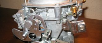
Solex carburetor for VAZ 21213 Niva device
The Solks 21073 carburetor of the Niva 21213 car has several jets in different systems. They allow you to accurately dose fuel, air, and emulsion entering the engine.
Fuel jets of the main metering systems (GDS) of the 1st and 2nd chambers of the Solex 21073 carburetor
The first chamber is 107.5, the second chamber is 117.5. See photo below.
Air jets of the main metering systems of the 1st and 2nd chambers of the Solex 21073 carburetor
The first chamber is 150, the second is 135.
fuel and air jets of the main metering systems (GDS) of the 21073 Solex carburetor
Calibrated hole in the fuel bypass fitting to the gas tank (return fitting)
calibrated hole in the fuel bypass fitting to the gas tank (“return”)
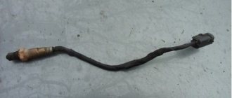
Fuel jet of the idle system (IAC) of the 21073 Solex carburetor
Calibration data - 39-44.
fuel jet of the idle speed system (IAC) of the 21073 Solex carburetor in the solenoid valve (EMV)
Air jet CXX carburetor 21073 Solex
air jet of the idle system (IAC) of the carburetor 21073 Solex
Fuel jet of the transition system of the second chamber of the carburetor 21073 Solex
See photo below. Marking - 70.
Fuel jet econostat carburetor 21073 Solex
econostat fuel jet and fuel jet of the transition system of the second chamber of the carburetor 21073 Solex with tubes
Fuel jet for economizer of power modes of carburetor 21073 Solex
fuel jet for economizer of power modes of carburetor 21073 Solex (economizer cover removed)
Notes and additions
— The location and number of Solex jets 2108, 21081, 21083 and other carburetors of this family are similar to the Solex carburetor 21073. Only their calibration data is different. Read more: “Solex carburetor jets.”
— Solex carburetor jets of various modifications are interchangeable, which creates a wide field for tuning and modification.
More articles on the design of the 21073 Solex carburetor
About 15 years ago I visited Tavria. The carb on it was a Solex. Gasoline consumption is less than 5 liters per hundred kilometers. Before the sale, the carb was replaced with a new one, 08 Solex, due to constant blockages, mainly in the XX system.
The next cars were Zhiguli, first with an 05 1300 engine, then with an 06 1600 engine. Both with Ozone carburetors. I couldn’t make friends with these Ozones. They didn't work as they should. They either pour water or sneeze. One fine day, at the dacha, Ozone in the VAZ 2105 was given a long life. There is nothing to replace, there are no spare parts, it cannot be repaired in the field. And you have to drive 180 km to the city. This is where the old Tavria Solex caught my eye, which, after cleaning and purging, was installed instead of Ozone. The drive was hastily made with a piece of cable and a roller from the Tavria carb drive. A test drive around the village showed that it was possible to drive. But on the highway it turned out that the engine was very reluctant to pick up speed, the throttle response was zero. And in the city, at traffic lights, it’s just torment. But the consumption on the Zhiguli remained 5 liters per hundred on the highway.
Afterwards, all sorts of experiments began with jets, flutes, sprayers and accelerator pump cams. At the same time, throttle spraying was tested. The intermediate results were different and very interesting. For example, wheel slipping with smoke on dry asphalt from a standstill and crazy gas mileage for an engine 05 - 1300 in the urban cycle. The end result is normal dynamics and consumption of 7-8 liters per hundred. The same carb migrated to the next VAZ 2104 car with a 1600 engine. True, I again had to experiment with jets, adjusting the carb to suit my needs and the increased engine volume. After the destruction of these four as a result of a meeting with KAMAZ, I purchased Niva 21213.
Description of the motor device 21213
The basis of the VAZ 21213 engine includes:
- cast iron cylinder block (BC) 21213-1002011;
- block head 21213-100301*;
- crankshaft 21213-1005015;
- connecting rod and piston group 21213-10040*.
The main difference between the 21213 engine and its predecessors was the increased cylinder diameter - 82 mm versus 76 and 79 mm. The center-to-center distance of 95 mm remains the same, and allows the block to be bored to a diameter of 82.8 mm. The design of the water jacket has changed. The working volume has increased by 100 cm3, but the engine dimensions have remained the same.
To install the crankshaft in the BC there are 5 supports: one each on the front and rear walls, 3 more on the ebb. The crankshaft parameters provide a piston stroke of 80 mm. The crankshaft is cast from cast iron and consists of 4 connecting rods and 5 main journals. The connecting rod journals have oil channels. The necks are separated by cheeks with counterweights. In previous VAZ engines, balancing counterweights were found only in the outer and central cheeks. The axial movement of the shaft is limited by thrust half-rings.
The piston group for the 21213 engine was developed anew. Pistons 21213-1004015 are cast from aluminum and reduced to a single mass of 347 g. The piston class (A, B, C, D, E) is determined by the outer diameter in increments of 0.01 mm. The shape of the piston is conical in height and oval in cross section. The hole for the pin is 22 mm, offset by 1.2 mm from the piston axis. The finger is locked with rings. There are 3 rings installed on the piston skirt:
- upper compression barrel;
- medium oil scraper with expansion coil spring;
- lower compression scraper type.
The connecting rod 21213-1004045 is forged from steel and processed together with the cover. A steel-bronze bushing is pressed into the upper head of the connecting rod. To fasten the connecting rod, M9x1.0x56 bolts are used.
The aluminum BC head is designed for the VAZ 21213 engine and is designed for compression from 10 bar. Installing a head from other motors may cause it to break. Cast iron seats and guide bushings for 4 intake and 4 exhaust valves are pressed into the head. The valves operate from the camshaft cams. The gap between the valve stem and the cam is adjusted with a bolt.
Similar article M103 Mercedes engine
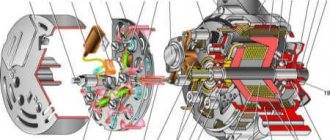
timing belt
The camshaft 21213-1006010 is made of cast iron and rests on 5 journals. The jaws are bleached to increase wear resistance. Axial movement of the shaft is limited by a thrust flange.
The timing belt is driven by a double-row bush-roller chain. In addition to the camshaft, the chain drives the oil pump. The drive is regulated by a semi-automatic tensioner with a shoe and damper. To prevent the chain from falling off when removing the camshaft sprocket, a limiter is provided next to the crankshaft drive sprocket.
Systems
The power supply system in the Niva 21213 engine is a 21073 Solers carburetor. The carburetor unit is two-chamber, the throttle valves operate sequentially. When the first chamber is 2/3 open, the throttle of the second chamber is engaged. At idle, the economizer turns on. The carburetor device includes:
- float chamber;
- 2 dosing systems;
- crankcase gas suction system;
- heating the throttle zone of the first chamber;
- blocking the second camera;
- economizer;
- econostat;
- diaphragm accelerator pump.
The ignition system in the 21213 engine is non-contact. The system is controlled by a switch using distributor signals. In general, the system is classic, without any special features.
Cooling of the motor occurs according to a typical scheme: liquid circulates through the water jacket in the BC and the block head. The pressure is created by a centrifugal pump connected by a belt drive to the crankshaft and generator. The radiator fan impeller works on suction, so in winter the radiator has to be covered with cardboard.