Today we will look at the location of fuses in VAZ cars of the tenth family, namely models 2110, 21102, 21103, 2111, 2112. We will also show where the fuses and relays are located on the diagram and talk about the purpose of each of them and how to replace the fuses with your own hands. We will also touch on the most common problems with fuses among owners of these cars, diagnostic methods and replacement.
I would like to say that car electrical systems, in particular fuses and relays in the VAZ 2110, 21102, 21103, 2111, 2112, are quite reliable. The service life depends on operating conditions and timely diagnosis and replacement with high-quality components.
Let's figure out why fuses are needed in a car. First of all, they are responsible for the safety of the wiring and other systems of the machine. It is important to understand that each specific fuse is responsible only for its task and in the event of a short circuit or failure, a fire is practically excluded. A specific fuse blows and this does not cause a chain failure of other systems.
Depending on the problem of failure of any component or part of the car for which the electrician is responsible, you need to understand whether the car can be operated with this malfunction or not. The traffic rules contain a list of faults that you cannot operate a car with. If you discover, for example, that the headlights have failed or the wipers are not working at all, you should immediately correct the problem. Well, you can drive a car with non-working power windows. By the way, if someone suddenly needs a high-quality website for business, then these guys make good websites WebFormata.ru
Fuse layout diagram for VAZ 2110, 2111, 2112
The photo shows fuses for VAZ 2110, 2111, 2112
As you can see, each fuse is numbered with a corresponding index.
In the above illustration, the unit is located on the left side of the steering column and is integrated into the instrument panel. Below are the values of the specific fuse in this mounting block. Table of fuse values for VAZ 2110, 2111, 2112.
| Fuse, no. | Current strength, Ampere | Values |
| F1 | 5 | Lamps for illuminating registration numbers, luggage compartment space, the entire left side of the vehicle's side lighting, as well as instrument lighting for dimensions and instruments. |
| F2 | 7,5 | Low beam left headlight |
| F3 | 10 | Left high beam |
| F4 | 10 | Front right fog lamp |
| F5 | 30 | Electric windows in doors |
| F6 | 15 | Cigarette lighter/lamp portable |
| F7 | 20 | Horn, engine radiator fan |
| F8 | 20 | Heated rear window |
| F9 | 20 | Windshield washer and wiper |
| F10 | 20 | Spare |
| F11 | 5 | Side light on the right side of the car |
| F12 | 7,5 | Low beam right headlight |
| F13 | 10 | High beam right headlight |
| F14 | 10 | Front left fog lamp |
| F15 | 20 | Heated seats |
| F16 | 10 | Left and right turn signals, hazard turn signals |
| F17 | 7,5 | Interior light, ignition switch illumination, brake lights, clock and computer illumination |
| F18 | 25 | Illumination of the glove compartment, heating controls, cigarette lighter |
| F19 | 10 | Reversing lamps, indication of instruments, computer, clock, serviceability of brake lights, door locking |
| F20 | 7,5 | Rear fog lights |
. Asks
: Sasha Muslimov.
The essence of the question
: where is the heater fuse on the VAZ-2110?
Yesterday the stove stopped working. It doesn't blow at all. Neither cold nor hot air. None of the speeds work. I turned the valves differently. I went into the fuse box and on the cover I still couldn’t figure out where the fuse is for the heater. Help!
VAZ-2115 fuses and relays, electrical diagrams
VAZ 2115
is a fairly common car model that can often be found on the streets of Russian cities. When something breaks down and an electrical device stops working, it causes inconvenience to the driver and passengers. In case of serious malfunctions, movement may become impossible or dangerous. For example, if the headlights stop working at night or the car stops starting.
Most of the causes of such problems lie in the fuse box. It is necessary to periodically check the fuses and relays of the VAZ-2115, clean and replace parts that have become unusable. This article will discuss which fuses are responsible for what in the “fifteenth” and how to solve many electrical problems.
Relay mounting block
The mounting block is located under the hood, near the windshield.
K1 – headlight cleaner relay
. If the headlight cleaners do not turn on, check fuses F1 and F7. Inspect the wiper mechanism; dust may have gotten into it or a stone has flown in, damaging or jamming its action.
K2 – relay-interrupter for direction indicators and hazard warning lights
. If your turn signals or hazard lights stop working, check fuses F2 and F16, this is a relay. If the hazard lights work but the turn signals do not, check the power handle, its contacts and connector. If only the emergency lights do not work, check the power button, contacts and wiring. Don't forget to check the turn signal bulbs. There may be a short circuit in one of the headlights. Carefully inspect the connectors and wiring for insulation damage.
If the turn signals work unstably or intermittently, this may be caused by poor contacts in the mounting block, as well as burnout or damage to its tracks. Contact may disappear not only in the block, but also in the headlights themselves, as well as on the way to them. If the wiring has been changed or something has been done to the wires, check them first.
K3 – windshield wiper relay.
If your wipers stop working, first check the relays and contacts. The steering column switch could also stop working or its contacts could oxidize. Inspect the wiper mechanism; due to poor tightening, the nuts securing the mechanism slats may have become loose, or a foreign object may have gotten in, interfering with their normal operation.
The motor could burn out, you can check its performance by applying voltage directly to it from the 12 V battery. Near the motor there is another fuse that protects it from overheating. It is located either on the trapezoid bracket or in the motor itself, depending on its type.
K4 – lamp performance monitoring relay.
K5 – power window relay
. If your power window does not go up or down, check fuse F6 and this relay. If the window lifting mechanism is of a cable type, it lowers normally but rises with difficulty, it is necessary to lubricate the cables and glass guides with silicone grease. To do this, you need to remove the door trim and get to the mechanism. The motor may have stopped working, in which case it needs to be replaced.
Sometimes it helps to close the glass by hitting the door to temporarily revive the motor. To disassemble the window lifter mechanism, you need to unscrew the bolts securing the brackets and disconnect the glass itself from the mechanism.
If only one window regulator does not work, the problem may be in the power button and its contacts.
K6 – horn relay
. If your horn stops working, check fuse F5, relay. The signal may not work due to a lack of contact in the steering wheel. Remove the steering column housing and look at the serviceability of the plates and contacts. Turn the steering wheel left and right; when turning, the mechanism may jam or the contacts may move. One bolt on the casing secures the position of the switch mounting bracket, the second secures the casing.
For the signal to work, you need to securely fix them, setting them in such a way that the contacts close when the switch is pressed. The contacts are located above the steering shaft. The design of the contacts in the steering wheel could also be damaged. Inspect the mechanism; the 3 screws and springs should reliably open and close the circuit.
K7 – rear window heating relay.
If the rear window fogs up and the heating stops working, check fuses F4 and F7, relays, contacts of the heating elements on the glass that may have been burnt or oxidized, as well as the switch button. The heating uses a high current; it would be a good idea to check the tracks on the mounting block board near the specified fuses and relays. The wire going from the switch to the rear window could have frayed and become one of the reasons.
K8 – high beam relay
. If only one high beam headlight stops working, check one of the fuses F14 or F15 and the bulb in the problem headlight. Inspect the headlight connector and its contacts. It’s better to call them, then the problem will be easier to find. Check the steering column high beam switch and its contacts. When moving towards you, the headlights should flash with high beams, when switching away from you, switch the low beam to high beam. If the distant one blinks but does not switch, it is most likely the problem.
K9 – low beam relay
.
If the low beam in one of your headlights stops working, check one of the fuses F12 or F13, and the lamp in the problem headlight. Check the headlight and low beam switch buttons if both headlights do not light. Contacts in the headlight sockets can also cause the lack of light.
Circuit breakers
F1 (10 A) - rear fog lights, their activation lamp on the panel.
Headlight cleaner motors (turn on). Headlight washer motor
. If your rear fog lamps do not work, check the button to turn them on. When connecting a PTF, a fuse is usually installed, which is located directly on the wire behind the button. Check it out. Check the lamps. The PTF lights only when the low beam is on; this should be taken into account when searching for the cause.
If the headlight cleaner or washer does not work, see the information about relay K1, and also check the fluid level in the washer reservoir and its pump.
F2 (10 A) - turn signals, their relay-breaker and hazard warning lights.
Hazard warning light
. See information about relay K2, the main problems and solutions are described there.
F3 (7.5 A) - interior lighting.
Individual light lamps.
Trunk lamp. Illumination of the ignition switch. Check engine lamp. Stop lights. Trip computer, clock
.
If your brake lights stop working, check the fuse, although it is unlikely to be the problem. In models VAZ-2114, VAZ-2115, rear lamps are a disease. The problem is the board on which the lamps are installed. The solution is to replace this board with a new one, in this case it is not known how long the new one will work. The simplest solution is to solder the wires to the lamps directly, or replace the connectors with connectors from another VAZ model, for example 2106.
If it's not the circuit board, check the brake light switch (frog) located by the brake pedal. This can only be the case if none of the brake lights are on, even on the spoiler. If the signal on the spoiler is on, but the others are not on, the problem is most likely in the rear light board. Also check the chips that connect to this board and their contacts. If these connectors fail, they must be replaced or the contacts inside them must be bent.
The VAZ-2114 model has two brake light lamps, the VAZ-2115 model has four. The lamps themselves may also fail individually, you just may not notice it. In some cases, it may be the wiring under the dashboard. If you don’t understand electrics, contact a car service center; most of them have long learned to deal with such problems and it will not be difficult for the technician to find the fault.
F4 (20 A) - portable lamp.
Heated rear window
. See information about relay K7.
F5 (20 A) - sound signal.
Radiator cooling fan.
For the sound signal, see information about relay K6
. If the fan does not work, first check the functionality of its motor. To do this, connect it directly to the battery. The fan should be spinning. If it works, check the coolant temperature sensor and its contacts. It might be the thermostat. Do not allow the engine to overheat by more than 100 degrees.
If the sensor is faulty, or a different type of sensor is installed, the arrow on the dashboard may show an incorrect temperature. Overheating is accompanied by boiling, bubbling or the release of vapors from under the coolant expansion tank cap.
The reason may be in the electronic control unit and in the temperature settings for turning the fan on and off. When the wires from the sensor on the upper pipe are disconnected and the ignition is on, the fan should work. This indicates the health of the electrical circuit. Also check the wiring that comes from the fan and all connectors. The wires could rub against the body, and the contacts in the connectors could melt or oxidize.
F6 (30 A) - electric windows
. See information about relay K5.
F7 (30 A) - stove motor.
Windshield washer and headlight cleaner motors (in their operating mode).
Cigarette lighter. Glove compartment lamp. Heated rear window (winding)
. Heater problems. If the stove operates only at the 3rd speed, and does not turn on at the first two, most likely the additional resistor through which voltage is supplied to the stove motor has burned out, or the contact on its connector has lost. The resistor is located above the gas pedal and looks like a plate.
If the stove does not work in any of the positions, check the switch itself on the panel and its contacts; the stove motor may also have burned out or its brushes may have worn out. To measure the voltage, look at the wiring or change the heater motor, you need to unscrew the heater fan casing, which is located under the hood. When installing a new motor, there may not be enough space to fit the entire motor into place. In this case, try either placing it sideways and then turning it, or first disassemble it into 2 parts and then assemble it in place. A new assembled motor costs about 800-1000 rubles.
The problem may be poor ground contact; check the nut under the panel that secures the motor. It is also its contact to the body.
F8 (7.5 A) - fog light on the right side.
F9 (7.5 A) - fog light on the left side
. Check the lamps in the headlights, the button on the panel. The fog lights turn on only together with the low beam when the ignition is turned on. Take this into account when diagnosing. Check the PTF relay installed under the hood. Usually mounted on the partition near the air intake. Check the wire connectors and lamp connectors in the headlights.
F10 (7.5 A) - dimensions on the left side.
Headlight switch lamp (on the panel).
License plate lighting. Engine compartment lamp. Illumination of the dashboard, cigarette lighter
.
F11 (7.5 A) - dimensions on the right side
. If the side lights on one side do not work, check one of these fuses and, of course, the lamps on the non-working side. Also check the lamp connectors, the headlight switch, its contacts and wiring. If only the tail lights do not work, check to see if the brake lights are working. It may be the rear light board or connectors. See also information about fuse F3. Check relay K4, which is responsible for the serviceability of the lamps, as well as the absence of damage to the tracks on the mounting block.
F12 (7.5 A) - Low beam in the right headlight.
F13 (7.5 A) - Low beam in the left headlight
. See information about relay K9.
F14 (7.5 A) - High beam in the left headlight.
High beam switching lamp (on the panel). F15 (7.5 A) - High beam in the right headlight
. See information about relay K8.
F16 (15 A) - turn signals, hazard warning lights.
Reversing lamp.
Relay for monitoring lamp performance. Indication of the on-board control system. Dashboard. Emergency oil pressure lamp. Handbrake lamp. Low brake fluid level lamp. Battery discharge lamp. Trip computer, clock. Generator field winding (when starting the engine)
.
Power fuses
The power fuse and relay block is located on the strip under the panel (dashboard), at the feet of the front passenger; to access you need to bend the plastic side panel.
Depending on the car model, the appearance of the unit may differ slightly from that shown in the photo.
The lowest relays and fuse
— fuel pump. When the ignition is turned on, the fuel pump turns on for 5 seconds to create pressure in the system. Check the ground and contacts of this unit, and also inspect the wiring. The wire from the relay to the pump, which runs along the floor under the casing, may be broken.
Topmost relay
— radiator cooling fan. If it is OK, see the information about fuse F5.
Mounting block connection diagram
Most serious electrical problems can be solved by replacing the fuse and relay mounting block. The price of such an assembled unit is about 1500-2000 rubles. Usually, due to oxidation of contacts, current surges, moisture ingress after washing, dust, dirt and other factors, printed circuit board tracks and contacts become green or black, and simply fail.
If your VAZ 2115 is several years old and nothing has been done to the block, then there is a very high probability of seeing all the problems described above when it is removed. Replacing the unit with a new one will avoid many future problems. The electrics will work as they should, most likely even better. There are often cases when, after replacement, devices that never worked before begin to work. Drivers get used to the car and do not know how it should be in fully working order.
Therefore, in case of serious problems, I advise you not to save money and change the unit. It would also be a good idea to replace the steering column switches - it will save a lot of nerves and time in the future, and it will just be a pleasure to drive a working car.
Another important point in case of electrical faults in the VAZ-2115 is the presence of good contact to the body. The block is grounded to the car body and uses it as a second wire. When the nut that secures the terminal of this contact is loosened, any strange behavior of the devices may begin. If interruptions and unstable operation of any components begin, check the reliability of this grounding to the housing.
Do you often have electrical problems? What ways can you suggest to solve such problems? Maybe there was some special case, write about it, it will be useful to other car enthusiasts.
The more modern a car becomes, the more different additional and factory options appear in it, improving the convenience of the driver and passengers, as well as affecting the control of the car as a whole. As a rule, all these options take energy from the battery.
Each electrical device in a car requires a certain amount of energy to operate. If the current increases above normal, the device may burn out. Therefore, to avoid such a situation, fuses are provided. They are located in the so-called fuse box. It is available in every car, regardless of its year of manufacture. As an example, we will consider the fuse box of the VAZ 2114.
Heater fuse for VAZ-2110
A 25 Ampere fuse is responsible for the operation of the heater controller.
If the stove does not work on a VAZ-2110, this may indicate that its fuse has failed. Also, of course, there are other reasons for failure.
The following two tabs change content below.
All my life I have been surrounded by cars! First, in the village, already in the first grade, I was rushing around on a tractor through the fields, then there was JAVA, then a penny. Now I am a third-year student at the Polytechnic Faculty of Automotive Engineering. I work part-time as a car mechanic and help repair cars for all my friends.
The first step is to check the fuse itself. It is located in the mounting block under the hood.
His ID is F18.
The main fuses and relays on the VAZ-2110, 21102, 21103, 2112 are located on the left side of the steering wheel, just below. The figure shows the symbols on the fuse mounting block.
Relay Description:
- K1 – lamp health monitoring relay;
- K2 – windshield wiper relay;
- K3 – relay-interrupter for direction indicators and hazard warning lights;
- K4 – headlight low beam relay;
- K5 – headlight high beam relay;
- K6 – additional relay;
- K7 – relay for turning on the heated rear window;
- K8 – backup relay (not installed on vehicles of the VAZ-2110 family);
F1–F20 – fuses - almost all vehicle circuits are protected by fuses designed for different rated currents. Exceptions are the following circuits: battery charging circuit, generator circuit (except for the field winding), ignition and engine starting. To find a faulty fuse, you should use fuses protected by fuses. Before this, it is necessary to find the cause of the blown fuse, eliminate it, and only then install a new fuse.
The table shows the circuits that each fuse protects, but on each model some of them may be missing due to the lack of certain devices (power windows, lock drives, etc.)
Do not replace fuses with jumpers. This can lead to failure of various devices.
Most fuses and auxiliary relays are located in a separate mounting block (Fig.) built into the instrument panel on the left side of the steering column. The conventional numbers of the plugs in the connecting blocks of the mounting block and the colors of the wires connected to them are shown in Fig. in the connecting blocks of the mounting block and the colors of the wires connected to them. The diagram of the internal connections of the mounting block is shown in Fig. .
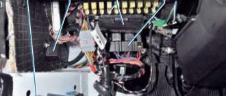
Fuse and relay box in the engine compartment
All relays (except for the relay for turning on the heated glass of the rear door), fuses of the engine management system are installed in the mounting block, which is located in the engine compartment of the car (on the left, behind the battery).
To gain access to the fuses and relays, press the latches from the side, back and front of the cover.
Relay/fuse panel number
| Relay/fuse number | Relay/fuse assignment | |
| 299-1 | 231(A). | Fog light relay |
| 753(B) | Headlight washer pump relay | |
| 299-2 | 233 | Heater Fan Relay |
| 597-1 | F1 (60 A), F2 (60 A) | Electronic control unit for ABS and ESP systems |
| 597-3 | F1 (50 A). F2 (25 A) | Exterior light switch, interior fuse box |
| 784 | 700(A), | Cooling fan relay |
| 474(B) | Air conditioning compressor relay | |
| 1047 | F1 (30 A), | Relay box power supply |
| F2 (25 A) | Injection relay power supply | |
| F3 (5 A), | Power supply for injection system relay, ECU | |
| F4 (15 A) | Not used | |
| 238(A). | Injection blocking relay | |
| 236(B) | Fuel pump relay |
Do not replace fuses with jumpers or fuses that are rated for a different amperage - this may result in damage to electrical devices and even a fire.
Attention!
The relay and fuse diagram may differ depending on the configuration and production date of the vehicle. Current diagrams of the mounting block are presented in the operating manual for the date of manufacture of the vehicle (download from the official website for a station wagon or van).
Let us remind you that you will find other useful instructions in the section Repair and operation of Lada Largus.
Table of circuits protected by fuses on the VAZ 2110
| Fuse number | Current strength, A | Circuits protected by a fuse |
| F1 | 5 | License plate lamps. Instrument lighting lamps. Side light indicator lamp. Trunk light. Left side marker lamps |
| F2 | 7,5 | Left headlight (low beam) |
| F3 | 10 | Left headlight (high beam) |
| F4 | 10 | Right fog lamp |
| F5 | 30 | Door window motors |
| F6 | 15 | portable lamp |
| F7 | 20 | Engine cooling fan electric motor. Sound signal |
| F8 | 20 | Rear window heating element. Relay (contacts) for turning on the heated rear window |
| F9 | 20 | Recirculation valve. Windshield and headlight cleaners and washers. Relay (coil) for turning on the rear window heating |
| F10 | 20 | Spare |
| F11 | 5 | Starboard side marker lamps |
| F12 | 7,5 | Right headlight (low beam) |
| F13 | 10 | Right headlight (high beam). Indicator lamp for turning on the high beam. |
| F14 | 10 | Left fog lamp |
| F15 | 20 | Electrically heated seats. Trunk lock lock |
| F16 | 10 | Relay-breaker for direction indicators and hazard warning lights (in hazard warning mode). Hazard warning lamp |
| F17 | 7,5 | Interior lighting lamp. Individual backlight lamp. Ignition switch illumination lamp. Brake light bulbs. Clock (or trip computer) |
| F18 | 25 | Glove box lighting lamp. Heater controller. Cigarette lighter |
| F19 | 10 | Locking door locks. Relay for monitoring the health of brake light lamps and side lights. Direction indicators with warning lamps. Reversing lamps. Generator excitation winding. On-board control system display unit. Instrument cluster. Clock (or trip computer) |
| F20 | 7,5 | Rear fog lamps |
Fuse and relay box in the interior of Lada Largus
Most fuses are installed in the fuse mounting block located in the passenger compartment, at the left end of the instrument panel, under a plastic cover.
The table and figure show the maximum possible set of fuses. On a specific vehicle, depending on the configuration, some fuses may be missing.
№
| Strength top, A | Color | Protected target | |
| F1 | 20 | Yellow | Windshield wiper, windshield wiper switch, heated tailgate relay |
| F2 | 5 | Beige | Instrument cluster, fuel pump relay, engine control unit (ECU) |
| F3 | 10 | Red | Brake light switch |
| F4 | 10 | Red | Diagnostic connector, immobilizer antenna unit, body electrical control unit |
| F5 | — | — | Reserve |
| F6 | — | — | Reserve |
| F7 | — | — | Reserve |
| F8 | — | — | Reserve |
| F9 | 10 | Red | Instrument cluster, left low beam |
| F10 | 10 | Red | Low beam right headlight |
| F11 | 10 | Red | Instrument cluster, left high beam |
| F12 | 10 | Red | High beam right headlight |
| F13 | 30 | Green | Rear door window motors |
| F14 | 30 | Green | Front door power window motors |
| F15 | 10 | Red | ABS electronic control unit, acceleration sensors, steering angle sensor |
| F16 | 15 | Blue | Electrically heated front seats |
| F17 | 15 | Blue | Sound signal |
| F18 | 10 | Red | Left front and rear parking lights |
| F19 F20 | 10 7,5 | Red Brown | Right front and rear parking lights, glove compartment lighting, instrument cluster lighting, hazard warning switch, HVAC control unit, audio system, cigarette lighter, central locking switch, front door power window switches, license plate lights, right lights front and rear position lights Rear fog light |
| F21 | 5 | Beige | Electrically heated exterior mirrors |
| F22 | — | Reserve | |
| F23 | — | — | Reserve |
| F24 | Reserve | ||
| F25 | — | Reserve | |
| F26 | 5 | Beige | SRS system |
| F27 | 20 | Yellow | Tailgate wiper motor, horn, TDC sensor, reverse light switch |
| F28 | 15 | Blue | Interior electrical control unit (energy saving mode) |
| F29 | 15 | Blue | Interior electrical control unit, diagnostic connector |
| F30 | 20 | Yellow | Interior electrical control unit |
| F31 | 15 | Blue | Fog lights, fog light relay |
| F32 | 30 | Green | Heated tailgate glass |
| F33 | — | Reserve | |
| F34 | — | Reserve | |
| F35 | — | Reserve | |
| F36 | 30 | Green | Electric motor for heating, air conditioning and ventilation systems |
| F37 | 5 | Beige | Electric exterior mirrors |
| F38 | 15 | Blue | Audio system, cigarette lighter |
| F39 | 10 | Red | HVAC Motor Relay |
Additional fuses and relays (fuel injection system)
Additional fuses and relays are installed behind the side trim of the console, secured with two screws, on the right side of the instrument panel:
Circuits protected by additional fuses (all fuses are 15 A) on the VAZ-2110:
Additional fuses:
1 – ignition module, controller; 2 – canister purge valve, vehicle speed sensor, oxygen (heating) sensor, air flow sensor; 3 – fuel pump relay, fuel pump, injectors.
Additional relays:
4 – electric fan relay; 5 – electric fuel pump relay; 6 – main relay (ignition relay).
There is a fog lamp fuse installed in the niche of the instrument panel behind the mounting block:
The order of conventional numbering of plugs in the connecting blocks of the mounting block and the colors of the wires connected to them:
Connection diagram of the mounting block (the outer number in the designation of the wire tip is the number of the block, and the inner number is the conventional number of the plug):
K1 – lamp health monitoring relay (contact jumpers are shown inside, which are installed instead of the relay); K2 – windshield wiper relay; K3 – relay-interrupter for direction indicators and hazard warning lights; K4 – headlight low beam relay; K5 – headlight high beam relay; K6 – additional relay; K7 – relay for turning on the heated rear window; K8 – backup relay (not installed on vehicles of the VAZ-2110 family).
The electrical equipment of any car is protected by fuses (fuse links). They are designed to take over the overloads that arise in the on-board network of the machine, and at the cost of their own integrity, save one or another of its elements. Some may be surprised, but VAZ-2106 cars also have fuses. Their appearance and design, of course, differ from those that we are used to seeing in modern cars, but they perform similar functions.
In this article we will talk about what VAZ-2106 fuses are, which one is responsible for what, where the mounting block is located and how to replace it with a more modern one.
Fuse and relay block Lada Largus
The relay and fuse box is also called the mounting block or black box. If problems are identified in the car related to electrical equipment, first check the fuses and relays. If they burn out, we replace them with the same ones, but first we must determine the cause of the burnout. The article contains a complete description of all Lada Largus mounting blocks.
How does a standard six fuse work?
Let's consider the design and operating principle of a standard “six” fuse-link. Unlike a modern knife fuse, it consists of only two parts: a ribbed plastic cylinder that acts as a body, and the insert itself, made of low-melting metal, located outside it. The contacts of the VAZ-2106 mounting block are made of copper (brass) and also have an open arrangement. From the point of view of electrical engineering, such a design cannot be called either reliable or safe, since all conductive elements, in fact, are not protected in any way.
Where is the mounting block located on the “six”?
The VAZ-2106 fuse box is located on the left side of the dashboard, under the instrument panel. Considering that all “sixes” were equipped with carburetor engines, there are no additional units with power inserts in them. They are all in one place. The mounting block consists of two boxes: upper and lower. For protection and insulation, they are covered with a plastic cover. On the inside there is a diagram, after studying which it will be easy to understand how the fuses are located in the VAZ-2106, which one is responsible for what and what the rating of each of them is.
Fuse box for injection VAZ 2115 electrical diagram
UAZ 3303 Zhivchik Logbook Installation of add. fuse box in UAZ 3303
A fairly common problem in domestic cars is the problem of breakdown of any electrical devices. In this case, the only way out is to check the condition of the fuses. Today we will talk in more detail about the fuses of the VAZ 2115 car on an injection engine. The fuse box of the VAZ 2115 car consists of two lines with fuses and this entire structure is secured with a nut to the vehicle body.
If you decide to remove the fuse lines, you will need to disconnect the battery.
So, this article provides answers to these fairly common questions:
- What is the fuse box on a VAZ 2115?
- How does the electrical circuit of a VAZ 2115 car work?
- How to properly install, repair and dismantle the mounting block?
Description of the fuse box
The fuses in a VAZ 2115 car are located in a special mounting block, which is located in the air supply box on the left side of the vehicle. The mounting block of the VAZ 2115 car includes all the most important sections of electronic circuits, while supplying them with the necessary fuses and relays. In addition, this device greatly simplifies the installation and repair work on circuits, because all wiring and relays are located in one place, and therefore their replacement is quite easy.
In the event of any breakdown of electronic equipment, the current in the node that is responsible for this device will increase, resulting in a short circuit.
The wire through which the current passes to the fuse burns out and melts, as a result of which the circuit breaks and the device turns off, but its integrity is maintained. That is, fuses protect the main parts from overheating in the event of a short circuit.
How to properly remove and install the mounting block?
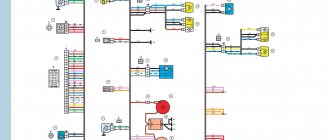
Wiring diagram VAZ 2115
If the electrical circuit is made with high quality, it will greatly facilitate the process of installing and removing electronic equipment. So, the withdrawal algorithm:
- Disconnect the wiring from the negative terminal of the battery;
- Open the hood and remove the cover. To do this, you need to press out 4 plastic latches;
- Move the rubber cover;
- Disconnect the upper block of the wiring harness;
- We unscrew the 2 nuts that secure the block;
- We take out the block from the compartment, which is located in front of the windshield;
- Disconnect the lower blocks of the wiring harnesses;
- Install fuses and relays in reverse order.
Carrying out independent repairs to the mounting block
Repairing the mounting block involves replacing printed circuit boards. So, the repair algorithm:
- Remove the mounting block;
- Remove the 8 screws that secure the bottom cover;
- Using a screwdriver, open the bottom cover;
- We check the condition of the tracks along which the current passes and the quality of soldering. If defects are detected, they must be eliminated, but if this is not possible, then carry out a complete replacement;
- Install the mounting block in reverse order.
Six fuse diagram
The “six” mounting block has only 16 fuse links. Each of them has a special designation and protects one or more electrical circuits.
| Designation | Rated current, A | Consumers |
| Cigarette lighter, signal, socket for portable lamp, brake lamps, interior lamps, clock | ||
| Electric motors and relays for interior heater, windshield washer, and windshield wiper | ||
| Indicator light for high beam headlights, left high beam headlight lamp | ||
| Right high beam lamp | ||
| Left low beam lamp | ||
| Right low beam lamp, rear fog lamp | ||
| Side lights (right rear light, left sidelight), luggage compartment light, right license plate light, cigarette lighter light, instrument panel light | ||
| Side lights (rear left light, right side light), left license plate light, engine compartment light, side light indicator | ||
| Oil pressure warning light, coolant temperature indicator, fuel level indicator, battery lack of charge warning light, throttle open indicator, rear window heating relay | ||
| Generator winding, voltage regulator relay | ||
| Not used (reserve) | ||
| Reserve | ||
| Rear window defroster | ||
| Electric cooling radiator fan drive | ||
| Alarm |
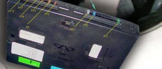
Main unit
VAZ 2114 fuse box diagram:
Its real appearance:
The main unit is located in the engine compartment, on its right side, if you are facing the car. The VAZ 2114 fuse box is painted black and is located in the rear, almost at the wipers. You can remove the cover by unclipping the two latches on the sides of the power supply. Inside you will see nine relays, labeled K1 to K9, and fuses, which are labeled F1 to F20. It is convenient that on the power supply cover you can see the electrical diagram of the unit, as well as all the designations of the power supply and relay. In the PP designation table, the first column is its designation, the second is the rated current, the third is the symbol of the element for which it is responsible.
Attention! Before replacing any fuses, you need to figure out which of the power supply elements is responsible for the device that is not functioning.
- is responsible for the washers and cleaning brushes of the headlights (if such an option is available);
- ensures the functionality of direction indicators and hazard warning lights;
- responsible for the windshield wiper;
- operation of car interior lighting lamps;
- operation of electric windows (if such an option is available);
- ensures the functionality of the horn;
- heated rear window (if available);
- is responsible for low beam headlights;
- responsible for high beam headlights;
Now let’s look at what the PPs in the VAZ 2114 are responsible for:
It would also be useful to know the generally accepted (they even say GOST) color designations for PP:
Which fuses in the “six” blow out most often?
If you happen to be the owner of a VAZ-2106, then you probably know that most often those fuses that “pull” energy-intensive devices are susceptible to failure. These are, for example, fusible links that protect the cigarette lighter, rear window defroster, and electric motors.
The cigarette lighter is a leader in this sense, since recently it has been used not only to light a cigarette, but also to connect various additional electricity consumers to the vehicle’s on-board network. These include electronic devices (recorders, navigators, radar detectors), compressors, and vacuum cleaners. It is because of them that the cigarette lighter fuse suffers, because in most cases none of us pays attention to the current consumed by the devices we use. If it exceeds the rating of the protective device, naturally it will withstand the load and melt, saving other elements of the circuit.
How to tell if a fuse has blown
Knowing what the VAZ-2106 fuses are responsible for, you can easily determine which one has failed when one of the devices refuses to work. If, for example, the lights in the luggage compartment stop working, check whether the license plate light or the low beam indicator light is on. If it doesn’t light up, we look for a fuse-link with the designation F-7 in the mounting block and diagnose it for serviceability.
The horn may not be working, then check if the interior lighting is working. If not, look for fuse F-1 and change it.
Where is it located and how can you remove the fuse box in the VAZ-2115
Of course, in order to look for a problem in a particular component of the car, you need to know its location. In the VAZ-2115, the designers decided to move the fuse box to the engine compartment - in the first generation Samara it was located in the cabin. Finding the block will not be difficult - it is located in a black box, near the left glass. Let's look at the decoding of the fuses located there. In particular:
- K1 – is responsible for the headlight cleaning system relay;
- K2 – alarm and relay for the turn signal switching system;
- K3 – windshield cleaning system;
- K4 – control of lamp performance;
- K5 – electric windows;
- K6 – sound signals;
- K7 – heated rear window;
- K8 – high beam;
- K9 – low beam.
It is worth drawing your attention to one more point. There is also a fuse box in the cabin
It should also be described in more detail. Here, in particular, there are 3 relays and fuses, as well as an electronic control unit. If we look at this block from top to bottom, we will see the following picture. The fuses will be distributed in the following order:
- 15-amp, responsible for the operation of the fuel pump;
- 7.5-amp - it is equipped with speed, crankshaft and mass air flow sensors, a valve located on the adsorber purge, and an electric fan relay;
- 7.5-amp - the electronic control unit is powered through it.
In addition, this block also contains 3 relays. One of them is the main thing. The other two are responsible for turning on the fuel pump and the electric cooling fan, respectively.
Replacing the fuse box located in the engine compartment is a very simple procedure, and every car enthusiast can do it without any problems. To do this, you only need to perform a few simple steps, spending a couple of minutes on everything.
In particular, first of all, for safety reasons, we remove the negative terminal from the battery. Next, remove the lid from the black box. After this, you should unscrew the two nuts - for this you will need a 10mm wrench. At the next stage, you need to disconnect the upper and lower connectors. In order to perform the last of these operations, it is necessary to lift the block. That's all. Now all that remains is to pull out the fuse box. In order to put it in place, all the manipulations described above are carried out in the reverse order.
An even simpler procedure is to replace the fuses themselves. The main thing here is to determine which one has failed. Next, everything is done very simply. The faulty fuse is removed from the corresponding socket and a new one is installed in its place. We recommend using tweezers for this simple manipulation. The thing is that fuses are small in size and have a flat shape. If your fingers are too thick, or, for example, your hands are frozen, this simple device will allow you to easily replace them without dropping anything.
To determine whether a fuse has failed or is functional, you can use one of the two most common methods. The first of these is a visual inspection. To do this, the suspect fuse should be removed from the socket and the conductive part should be inspected for integrity.
However, the problem is not always visible to the naked eye. Therefore, a more reliable and accurate method of checking the functionality of fuses is the following. It’s worth warning right away - it’s a little more complicated than the first option. So, to check, you should first turn on a non-working consumer of electricity, for example, high beam headlights. Next, without removing the fuse, we check the voltage at both ends. If it is missing somewhere, you can safely conclude that this element is faulty.
One more, very important piece of advice. Before replacing a blown fuse, you should find the reason why it failed. Otherwise, you risk repeating the replacement manipulations again. Frequently blown fuses may well indicate problems with the electrical wiring. If you do not have the necessary knowledge, then it would be best to turn to specialists, since delaying solving the problem can ultimately result in more serious consequences than a burnt-out protection element.
Problems with the mounting block and their solution
Many owners of "sixes" are faced with the problem of frequent power surges. It can be caused either by a malfunction of the generator or voltage regulator, or by problems with the mounting block. If you have established that it is the cause of the problems, do not rush to replace it with a similar one, just a new one. Better take a closer look at the mounting block from GAZ-3110. How is it better? The fact that it will allow installing fuses on the VAZ-2106, which are equipped with “installers” of modern cars. They are easier to buy and more reliable. In addition, the Volga mounting block is much more compact than the “six” one. It is made in the form of a single strip, accommodating only 12 fuse links.