We remove the electric fan unit if it is necessary to replace the electric motor or if there is strong vibration caused by dirt adhering to the impellers.
The design of the fan unit may differ depending on the modification and year of manufacture. car.
There are two ways to remove electric fans: with removing the radiator and without removing the radiator. Below is a method without completely removing it. (if it’s more convenient for you to remove it, see here).
In the photo the hood is removed for clarity.
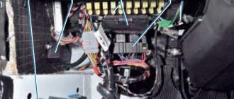
We disconnect the connectors of the wires supplying the electric fans. (This work is done from the engine compartment by touch, but for clarity, the operation is shown from below with the mudguards removed.)
Remove the spare wheel pipe (see here).
Unscrew the radiator mounting bolts (see here)
We tilt the radiator towards the engine.
. and remove the fans from the engine compartment.
The electric fan casing rests on the body cross member through rubber bushings.
To replace the fan motor.
. Using a 10mm head, unscrew the three nuts.
. and remove the electric motor with the impeller.
Use a slotted screwdriver to lift the locking element of the lock washer, move and remove the washer. second mounting option
and remove the impeller from the motor shaft. another impeller option
Pay attention to the depressions in the impeller hub, into which the motor shaft pin must fit during installation.
Disconnect the motor wiring.
We remove the electric motor.
Install the electric fan in reverse order.
System structure and principle of turning on fans
Everything works as follows.
- The radiator and engine block are looped into a single system using pipes. Between them there is a rheostat - a damper with a temperature-sensitive element inside.
- When a certain temperature is reached, the damper opens and the liquid begins to circulate in a large circle.
- If passive cooling fails, the engine temperature rises. The head cooling fans come into play. When the temperature limit is overcome, the DTOZh sends an impulse to the BC.
- The processed signal closes the relay and the fan turns on. To improve system performance, the devices are paired. Dubbing helps prevent overheating if one of the devices breaks down. At the same time, the connection diagram for active coolers implies their simultaneous and separate activation.
The Chevrolet Niva interior heater fan is also used to cool the engine. Part of the system has a slight effect on the temperature, but in an emergency it can affect the operation of the engine.
Design of the internal combustion engine cooling system and components
The design of the VAZ 21213 Niva engine cooling system (as well as models 2131, 21214) is quite simple and has not actually changed since its development. The unit is of the liquid type with closed forced circulation of the cooler. On carburetor systems, the fan is mechanically driven. The injection circuit provides for 2 electric fans on the Niva 2131. The main components of the cooling unit circuit are:
- Mechanical pump. It is mounted in the cylinder block (BC) at the front, the impeller is partially immersed in the cooling liquid (operates using a belt drive).
- The thermostat is mounted to the right of (BC). Its pipes go to the radiator and water jacket.
- Radiator and two plastic tanks on both sides of the front of the engine.
- Fan with air diffuser on the inside of the radiator.
- An expansion tank with a cap and valves connected to the radiator with a pipe.
- Interior heating heat exchanger with tap.
Purpose and design
This is a module designed to be included in the on-board circuit of a motor that consumes high current. The fan motor is powered by electricity with a current of 20-35A, which is unacceptable for inclusion in a low-voltage control system - the wiring will melt. The Niva has only three relays, two for the left and right fans separately and one common. Each device has its own number in the on-board network. The principle of operation and purpose of the relay is relevant for cars of all types 2004, 2010, 2020 and other years of production.
Inside, the relays have an identical design. There is a low part, a transformer and a high part. Also two pairs of contacts, one normally closed, the second open. When a pulse is applied to the lower part, a magnetic field is formed on the windings, and the contact group on the high side closes - power is supplied to the fan motor.
The cooling screw operates in two modes. When the engine heats up to 99 degrees Celsius, the first fan is turned on, after passing the 101⁰C mark, the second one is connected. If the system cannot cope, the motors switch to higher speeds.
Fan relay diagram
The figure shows the power supply circuit for the electric fans of the cooling system of the installation. Design elements are presented by numbers.
- 1/7 – left and right fan motors;
- 2 – additional power relay;
- 3 – fuse;
- 4 – power controller;
- 5 – auxiliary resistor;
- 6/8 – main relay for turning on the right and left electric motor, respectively;
- A/C – negative/positive battery terminal;
- B – to the main ignition relay.
Cooling fan Niva Chevrolet
Niva Chevrolet. Fans, MOSFETs and temperature - Let's connect! (1)
Also, both fans will not turn on if the coolant temperature sensor fails. If this resistor burns out or the relay fails, the cooling fan on the Chevrolet Niva will stop turning on at low speed.
The topic is like this, it doesn’t turn on and that’s it. replaced the temperature sensor with a resistance (I found 66...
But we are interested in what role such a small device as a relay, of which there are three on the Chevrolet Niva, plays in this process. To do this, you need to open the right front door of the Shevik and look from underneath at the dashboard. According to this sensor, the system understands how much the coolant temperature has increased or decreased.
Due to the increased temperature inside the engine compartment, there are cases of deformation of the plastic fan casings, and when they are turned on, the rotating fan blades touch the casing.
The principle of operation of the device and its placement on the Chevrolet Niva On the front part of the product there is a diagram of the arrangement of contacts, according to which we will consider its principle of operation.
In turn, the contacts: It is to these contacts that the power cables from the fan motor are connected. Thus, power is supplied to the electric motor of the device.
The activation process takes a fraction of a second. So, when the temperature in the engine rises, the sensor is triggered and sends an impulse to the control circuit. In turn, voltage is induced in the circuit, which is not supplied by the relay, but it turns on the direct cooling device.
A relay is a replaceable part that, if it fails, requires replacement, but not repair. Some craftsmen are trying to repair them, but there is no need for this, since one product costs from 50 to 80 rubles, depending on the manufacturer. For Chevrolet Niva, it is recommended to use a relay made in Russia.
They are the optimal solution for VAZ family cars. Where are the fan relays on the Chevrolet Niva?
Last messages
To answer this question, it is worth noting that there are two cooling devices on the Chevrolet Niva, so the corresponding relay is responsible for the operation of each. So, having discovered a malfunction in the car’s cooling system, it is worth paying attention to the suitability of the relay.
But first they must be removed from the installation site. To do this, you need to open the right front door of the Shevik and look from underneath at the dashboard.
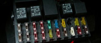
It is there, under the cover of the mounting block, that the fan and fuel pump control relays, as well as the fuses for these devices, are located. In the photo below you can see where the control switches are located: To remove the device from its seat, you need to pull it out of the installed socket. To do this, grab the product with one hand and pull.
Pulley fan sensor
The coolant temperature sensor plays the role of supplying a pulse to turn on the fans. When a certain temperature is reached, the device sends a signal to the ECU and the fans are activated. In versions where the BC is located in the cabin, you can make adjustments to the sensor response threshold.
Purpose and functions
The device has a single role - to prevent boiling of the coolant and overheating of the power plant. Thus, turning on at a certain moment, the part equalizes the temperature of the engine and stabilizes its behavior.
Operating principle and location
The sensor works as follows.
- The temperature-sensitive sensor is programmed to pulse at a certain temperature.
- When the threshold is reached, the sensor sends a signal to the ECU and the first fan turns on.
- If the motor temperature rises further, the second relay is activated and the remaining fan is connected.
Heating and ventilation system. VAZ 21213, 21214 (Niva)
The cooling system is liquid, closed type, with forced circulation. The tightness of the system is ensured by valves in the expansion tank plug. The inlet valve is normally open (the gap between it and the rubber gasket is 0.5–1.1 mm) - in this case, the system communicates with the expansion tank. When the engine heats up, the liquid expands and is forced into the tank; when it cools, it returns back. The inlet valve closes when there is a sharp increase in pressure in the system (boiling liquid), while the outlet valve is also closed. It opens when the pressure in the system reaches approximately 0.5 kgf/cm2, which increases the boiling point of the liquid and reduces its losses. The thermal operating conditions of the engine are maintained by a thermostat and a radiator fan. On a carburetor engine, the fan is mechanically driven and mounted on the coolant pump pulley. On an engine equipped with an injection system, two electric fans are installed in front of the radiator and are activated by command from the electronic engine control unit.
| Carburetor engine cooling system Injection engine cooling system |
Photo
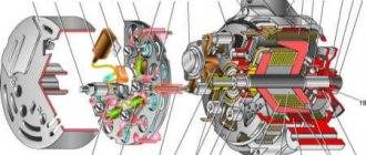
The coolant pump is a vane, centrifugal type, driven from the crankshaft pulley by a V-belt. The pump housing is aluminum. The roller rotates in a double-row bearing with a lifetime supply of lubricant. The outer ring of the bearing is locked with a screw. A pulley hub is pressed onto the front end of the roller, and a plastic impeller is pressed onto the rear end. For the correct position of the pump pulley groove, the distance from the mating surface of the pump cover to the outer end of the hub must be 84.4 ± 0.1 mm. When installing the cover with the gasket, check the gap of 0.9–1.3 mm between the impeller blades and the pump housing. To do this, you can use plasticine rollers: they are placed on equidistant impeller blades, a cover is installed, the nuts securing it are tightened, then the cover is removed and the remaining thickness of the plasticine is measured - it is equal to the gap.
Axial and radial play in the pump bearing that can be felt by hand is not allowed. If the bearing or self-pressing seal of the pump fails, it is recommended to replace the pump cover complete with the roller and impeller.
The redistribution of liquid flows is controlled by a thermostat with a solid heat-sensitive element. On a cold engine, the thermostat valve closes the pipe leading to the radiator, and the liquid circulates only in a small circle (through the thermostat bypass pipe), bypassing the radiator. The small circle includes the heater radiator, intake manifold, carburetor heating unit (on engine 21213) or throttle assembly (on engine 21214). At a temperature of 78–85°C, the valve begins to move, opening the main pipe; in this case, part of the liquid circulates in a large circle through the radiator. At a temperature of about 90°C, the main valve opens completely, and the bypass valve closes, and all the liquid circulates through the engine radiator. The main valve stroke must be at least 6.0 mm.
You can evaluate the serviceability of the thermostat by heating the lower radiator pipe: it should be cold until the liquid temperature (according to the indicator) reaches 80–85°C, and hot when it rises to 85–90°C. The thermostat is beyond repair. In case of malfunction, loss of tightness, or deformation of the pipes, it is replaced.
The radiator consists of two vertical plastic tanks (the left one has a baffle) and two horizontal rows of round aluminum tubes with pressed-on cooling plates. To increase cooling efficiency, the plates are stamped with a notch. The tubes are connected to the tanks through a rubber gasket. The liquid is supplied through the upper pipe and discharged through the lower. There is a coolant drain plug at the bottom of the left reservoir.
For better radiator airflow, casings are designed to direct air flow from the fan(s).
On the 21213 engine, the main fan shroud consists of two halves (lower and upper), the lower half has a rubber seal on the radiator side. An additional guide casing is installed in front of the radiator. On the 21214 engine, electric fans rotate in a casing in front of the radiator.
The expansion tank is made of translucent polyethylene, which allows you to visually monitor the fluid level (3–5 cm above the “MIN” mark on a cold engine).
To monitor the coolant temperature, a sensor is screwed into the engine cylinder head and is connected to a temperature gauge on the dashboard. An additional temperature sensor is installed in the exhaust pipe of the 21214 engine, which provides information to the electronic engine control unit (see here).
The heating system is described here.
Video
Job
The Shniva cooling system has two active cooling elements. There is a fan for the heater radiator and the main heat exchanger. The following information is relevant for cars of 2010 and other model years.
Fuses are responsible for the correct, stable operation of devices. Fuse links will protect the device from power surges and short circuits.
Pulley fan fuse: where is it located?
Located in close proximity to the corresponding relays. The stove insert is located in the main mounting block under number F18. A 25 amp fuse protects multiple circuits at once.
Cooling fans do not turn on
Cooling fans do not turn on
Post by Andrey55 » Aug 24, 2020, 10:57 am
Re: Cooling fans won't turn on
Post by Leon71 » 24 Aug 2020, 17:15
Re: Cooling fans won't turn on
Post by Andrey55 » August 24, 2020, 6:25 pm
Re: Cooling fans won't turn on
Message by Slava N » 24 Aug 2020, 21:43
Re: Cooling fans won't turn on
Post by Andrey55 » 25 Aug 2020, 08:19
Re: Cooling fans won't turn on
Post by Sash » 25 Aug 2020, 08:50
Re: Cooling fans won't turn on
Post by Andrey55 » Aug 25, 2020, 01:16 pm
Re: Cooling fans won't turn on
Post by Sash » Aug 25, 2020, 1:30 pm
Re: Cooling fans won't turn on
Message by Slava N » 25 Aug 2020, 21:21
Re: Cooling fans won't turn on
Post by Vadyana » 06 Dec 2020, 12:20
Re: Cooling fans won't turn on
Post by Warlock » 07 Dec 2020, 10:04
Re: Cooling fans won't turn on
Post by Vadyana » 07 Dec 2020, 10:32
Re: Cooling fans won't turn on
Post by Warlock » 08 Dec 2020, 23:46
Re: Cooling fans won't turn on
Post by Sash » 09 Dec 2020, 21:31
Re: Cooling fans won't turn on
Post by Vadyana » 11 Dec 2020, 14:57
Possible malfunctions and their causes
If the fans do not turn on on time, the problem may be hiding in the following places.
- Relays or fuses have blown.
- DTOZH does not work correctly.
- The wiring of the device is damaged.
- Incorrect ECU settings.
- The fan motor is damaged or shorted.
Checking the functionality of the sensor, relays and fuses
The DTOZH is responsible for the operation of the fans; it is easy to check.
- Prepare a thermometer, multimeter, kettle or bowl of cool water.
- Immerse the sensor in a container and put it on fire, at the same time immerse the thermometer in water.
- When passing thresholds of 5 degrees, you should connect the multimeter to the sensor in resistance mode. At the same time, record the data.
- After heating the water to a boil, take the last measurements and compare the results with the reference table below. If the device indicators differ by more than 10% from the standard, the sensor is changed.
Forced activation of cooling fans
To make this possible, car enthusiasts install an additional switch into the device circuit and power it directly from the battery. The operation of the electronics is disrupted and the on-board computer may generate an error.
To fake the device, users on the network recommend using a scheme.
A relay and a forced switch are added here.
Replacing the Fan Relay
Due to the simplicity of the design, the procedure is performed according to a standard scenario. Access to the mounting block is opened, the terminal of the relay contact group is disconnected. Next, the device is unscrewed from the panel and replaced with a new one.
Fuel system
Fuel tank, Water level sensor, Fuel level sensor, Tank vent valve, Fuel tank button, Fuel tank cap, Fuel neck, Fuel pump, Fuel pump, Fuel pump strainer, Fuel pump gasket, Fuel pump relay, Fuel injector, Injector ring, Throttle valve, Sensor throttle valve, Throttle pipe, Idle air regulator, Air receiver, Throttle valve heating tube, Turbine (turbocharger), Turbine gasket, Solenoid valve, Injection pump, Injection pump valve, Compressor, Compressor gasket, Carburetor, Fuel rail (rail), Fuel pressure regulator , Fuel line, Fuel valve, Fuel hose, Fuel pipe, Air flow meter, Engine control unit, Air pipe, Intake manifold, Intake manifold gasket, Additional air pump, Fuel pump, Gas pedal, Potentiometer, Throttle cable
Possible faults
To avoid problems with engine overheating, it is necessary to monitor and maintain the Niva’s cooling system.
You should check the antifreeze level in the expansion tank more often. Due to the reliability of cooling, there are not many malfunctions in it:
- When the car heats up to maximum in any weather, and the main radiator pipes are cold, the thermostat has broken. The element is not repaired, only changed.
- Electric fans turn on at random, including when the engine is cold, but if they overheat, they may not start. This means that the sensor transmitting temperature data to the controller has failed and must be replaced.
- When the indicator on the panel gives inaccurate data or does not show the temperature, you need to change the second sensor located in the cylinder head.
- The fluid level in the tank is constantly decreasing. It is necessary to look for and eliminate leaks in the pipes or in one of the radiators.
It is important to periodically check for play in the water pump shaft. Its appearance indicates wear of the bearing; it is necessary to change the pump as soon as possible.
The connection diagram for Niva VAZ-21214 fans is identical to the diagram for other cars of the VAZ family. The only difference is the presence of two fans, which are turned on using two relays. This is caused by the engine working under heavy loads when driving off-road. In city conditions this is practically not necessary, with the possible exception of driving in traffic jams in hot weather. When turned on, fans create some discomfort as they make noise. You can reduce noise by reducing the rotation speed of the electric motors or turning off one of the fans. In the second case, the second fan can be turned on forcibly using a button or key.