Cars admin26.02.2020
1200 rub. for the photo report
We pay for photo reports on car repairs. Earnings from 10,000 rubles/month.
Write:
It won’t be difficult to remove the starter on a VAZ 21214 (Niva) with your own hands. To get to it, you first need to remove the engine air filter box. And then unscrew the 3 bolts securing the car starter (two starter bolts from under the hood and one from under the car), although craftsmen often do not screw in the third bolt to make it easier to dismantle the starter, because access to the lower mounting bolt is from under the car.
Tools needed for removal:
- The key is "13".
- Ratchet with small extension.
- Head at "10".
Briefly, you learned how to remove the starter on 21214, and now let’s begin the removal in order:
- disconnect the terminal from the battery;
- disconnect the flow meter connector;
- disconnect the clamp of the air filter housing pipe, dismantle the box itself (by unscrewing the 4 fastening bolts) and put it aside;
- remove the front support bracket securing the intake pipe to the engine support bracket;
- disconnect the starter heat shield from the exhaust manifold and from the engine support bracket;
- using a key set to “13”, you need to unscrew the bolt of the upper fastening of the starter to the clutch housing (this bolt also secures the rear support bracket of the intake pipe to the clutch housing);
- in the same way, unscrew the bolt of the middle and lower fastening of the starter, then move the starter forward;
- disconnect the traction relay control wire;
- Using the head at “13”, unscrew the nut of the “positive” wire and remove the starter from Niva 21214;
- move the starter along the cylinder block to the side and remove it;
- removing the starter from a carburetor engine is quite easy due to the lack of support brackets for the intake pipe;
- We install the starter in the reverse order.
You can clearly see the entire process of removing the VAZ 21214 starter in the video.
Lada 4x4 (VAZ-21214): Removing and checking the starter
We remove the starter on an inspection ditch or overpass.
Disconnect the wire terminal from the negative terminal of the battery.
Remove the rear mudguard of the engine compartment (see “Removing the mudguards of the engine compartment,” p. 282).
The gear should move easily along the shaft without jamming. If the gear sticks on the shaft, the drive must be replaced.
To check the starter, we connect the “positive” terminal of the battery to the upper contact bolt of the traction relay with wires for “lighting”, and the “negative” terminal to the starter housing.
Using a screwdriver, we bridge the upper contact bolt and the control terminal of the traction relay.
When carrying out this operation, care must be taken, since sparking is possible in the area where the terminals are closed. Do not connect the screwdriver to ground when connecting the leads.
In this case, the drive gear should move out and the starter motor should turn on. Otherwise, check the electric motor and starter traction relay. To check the electric motor.
. We connect the “positive” terminal of the battery with wires to the lower contact bolt of the traction relay, and the “negative” terminal to the starter housing.
In this case, the motor shaft must rotate. Otherwise, the electric motor is faulty.
To check the traction relay, we connect it with wires. . the “positive” terminal of the battery is connected to the control terminal of the traction relay, and the “negative” terminal is connected to the starter housing.
In this case, the drive gear should move out. If this does not happen, the traction relay is faulty. Install the starter in reverse order.
How to remove the Niva 21214 starter in 10 minutes. The cause of the malfunction of the removed starter NIVA VAZ 21214
Preparation for quick removal of the starter in extreme conditions. Quickly remove the starter and eliminate the cause of a possible malfunction. How to remove the acoustic pipe from a Niva receiver Why do you need an acoustic pipe https://www.youtube.com/watch?v=fXPZ5dVIEXQ As you noticed, the lower bolt of the starter was deliberately never screwed in again, after the first removal of the starter during the initial period of operation of the car. Also, the heat shield of the starter, whose lower mounting bolt quickly sticks when driving through mud, was not put in place. Because of this, in order to remove the screen, you have to cut off the lower attachment point or tear the screen itself. I don't want to go through this procedure a second time. The fact that there is no lower mounting bolt for the starter and a heat shield has its advantage for field drivers who often operate their vehicles, for example, in the conditions of Siberian swamps, river fords and frosts. Very often the cause of a starter malfunction is simple. For example, as in this video, or even funnier - the red wire (also shown in the video) from the solenoid relay has simply oxidized or weakened. It is enough to MOVE it and the starter will spin. You can make the starter spin if the nickels in the solenoid relay are burned by closing (carefully, with something not large in size, but massive and iron, without touching the mass of the engine body) the power wires on the solenoid relay. It's easy to do all this without a screen. And if necessary, the starter can be easily removed. It happens, for example, that the starter breaks down, and the car is parked at the entrance, and it’s -30 outside! Yes, even in the summer! You still need to remove the starter. Negotiate with your neighbor about a garage? Or take it to service? But you can remove it EASILY AND QUICKLY yourself, right at the entrance. Buy a new starter or solenoid relay from your local store. And an hour later the car drove off. And if the car is parked in a puddle or mud, then crawl under the car and turn the bottom bolt? In short, there are many life situations where the absence of a bolt and a heat shield will greatly simplify your life. The author of the video does not pretend that others will perceive his opinion and his proposed method of solving the problem as the only correct one. Decide this for yourself. The author simply suggested the option: “How to remove the Niva 21214 starter in 10 minutes and determine the cause of the malfunction of the removed Niva 21214 starter” https://youtu.be/n_PmQADIfNg
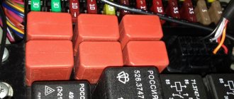
Mounting blocks for Lada 4×4 2019
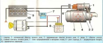
1 — engine control system fuse box;
2 — windshield wiper relay; 3 — fuse blocks; 4 — relay block of the engine control system. The fourth relay block is located above the gas pedal.
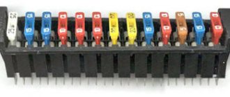
| №1 | Rear fog lamp relay |
| №2 | Rear window heating relay |
| №3 | Low beam relay |
| №4 | High beam relay |
The turn signal relay (part number 8450082700, 9-pin), as well as the windshield wiper relay, are located under the trim in the driver’s feet, to the left of the fuse mounting block.
The main power supply in these models is located under the lower edge of the instrument panel protection. Additional fuses in Niva 21214 for the injector are located to the left. This block is responsible for controlling fuel injection. There are also relays for monitoring the operation of the wipers and a set responsible for the motion control system.
Another fuse box is installed in the body to the left of the main one. They are responsible for the cooling system and how the engine works. There is also a diagnostic connector. The relay that controls the starter is located either next to the main power supply, or under the hood next to the brake fluid reservoir.
1 — engine control system fuse box; 2 — windshield wiper relay; 3 — fuse blocks; 4 — relay block of the engine control system.
The main difference between the schemes of old and new Niva lies in the method of connecting the additional mounting block, which is located below.
| New additional block | Old additional block | ||||
| Fuse no. | Current (amps) | What is he responsible for? | Fuse no. | Current (amps) | What is he responsible for? |
| 11 | 8 | Turn signal lamps, relay-breaker for turn signals and emergency lights | 11 | 8 | Reserve |
| 12 | 8 | Daytime running light relay, Daytime running light bulbs | 12 | 8 | Reserve |
| 13 | 8 | Rear fog lights and their relay | 13 | 8 | Fog lights and their relays |
| 14 | 16 | Cigarette lighter | 14 | 16 | Cigarette lighter |
| 15 | 16 | Reserve | 15 | 16 | Reserve |
| 16 | 8 | Reserve | 16 | 8 | Reserve |
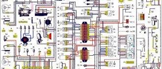
1. Front lights.2. Side direction indicators.3. Windshield washer motor.4. Headlight washer motor*.5. Switch.6. Rechargeable battery.7. Starter VAZ-21213.8. Generator.9. Headlights.10. Geared motors for headlight cleaners*.11. Sound signal.12. Spark plugs.13. Carburetor limit switch.14.
Carburetor solenoid valve.15. Ignition coil.16. Windshield wiper motor gearbox.17. Carburetor solenoid valve control unit.18. Ignition distributor sensor.19. Coolant temperature indicator sensor.20. Insufficient oil pressure indicator sensor.21.
Portable lamp socket**.22. Insufficient brake fluid level indicator sensor.23. Windshield wiper relay-breaker.24. Relay for turning on rear fog light lamps***.25. Relay for turning on the rear window heating element.26. Relay for turning on the headlight cleaners and washer*.27.
Relay for turning on low beam headlights.28. Headlight high beam relay.30. Starter activation relay.31. Relay-breaker for hazard warning lights and direction indicators.32. Heater electric motor.33. Additional resistor for heater electric motor.34. Illumination lamps for heater control levers.35.
External lighting lamp switch.36. Main fuse block.37. Additional fuse block.38. Reversing light switch.39. Brake light switch.40. Regulator for instrument lighting lamps.41. Ignition switch.42. Three-lever switch.43. Hazard switch.44.
Switch for headlight cleaners and washers.45. Heater motor switch.46. Rear window heating element switch.47. Rear fog light switch.48. Lamp switches located in the door pillars.49. Interior lighting lamps.50. Cigarette lighter VAZ-21213.51.
Switch for the carburetor choke indicator lamp.52. Indicator lamp for closing the carburetor air damper.53. Switch for the differential lock indicator lamp.54. Parking brake indicator lamp switch.55. Level indicator and fuel reserve sensor.56.
Instrument cluster.57. Rear window washer motor.58. Tail lights.59. Block for connecting additional brake lights.60. Blocks for connecting side marker indicators.61. Pads for connecting to the rear window heating element.62. License plate lights.63. Rear window wiper motor.
The order of conventional numbering in the blocks: A - headlight and rear window windshield wipers, windshield wiper relay breaker; B — ignition distributor sensor; B — relay-interrupter for alarm and direction indicators; G - switch; D — three-lever switch; E - hazard warning switch; F - relay for turning on the rear fog light lamps; Z — rear lights; And - instrument clusters of VAZ-21213.
In the instrument panel wiring harness, the second ends of the white wires are brought together to one point, which is connected to the instrument lighting control. The second ends of the black wires are also brought together to a point connected to ground. The second ends of the yellow wires with a blue stripe are brought together to a point connected to terminal “A” of the main fuse block. And the second ends of the orange wires are also brought together to a point connected to terminal “B” of the main fuse block.
The fuses in VAZ cars, as well as in the Niva, are located directly inside the car; they are covered by a shield, usually on the dashboard.
This allows, if necessary, to disassemble and carry out repairs using available tools. This approach is especially helpful in cold weather - there is no need to carry out repairs outside, and the cost of self-replacement will be much lower than in a service center.
The above circuit includes components such as relays and fuses. The mounting block includes the following elements presented in the table.
| Element designation | Protected Circuits |
| Relay | |
| K1 | Responsible for the light bulbs inside |
| K2 | Proper operation of windshield wipers and wipers. |
| K3 | Device for designating sensors indicating the direction of turns. |
| K4, K5 | Low and high beam blocks. |
| K6, K7 | Connection of non-fixed assets. |
| K7 | Rear window heating unit. |
| Circuit breakers | |
| F1 | Signal lights, license plate lights, trunk and glove compartment lights, 5A. |
| F2 | Low beam left side lighting, 7.5A. |
| F3 | Left headlights, high beam, 10A. |
| F4 | Fog lighting, left headlights, 10A. |
| F5 | Fuse for power windows, 30A. |
| F6 | For connecting portable lighting, 15A. |
| F7 | The unit responsible for the engine cooling fan, as well as for triggering the sound signal, 20A. |
| F8 | Heated rear windows, 20A. |
| F9 | Recirculation unit, cleaning headlights, windshield; 20A. |
| F10 | Additional, maybe for battery charging. |
| F11 | Side light right, 5A. |
| F12 | Right headlight, low beam, 7.5A. |
| Ф13,14 | Fog lighting, right headlights, 10A. |
| F15 | Fuse for heated seats and closing the luggage compartment, 20A. |
| F16 | Alarm system operation, 10A. |
| F17 | Internal light, serviceability of the on-board computer, 7.5A. |
| F18 | Responsible for the cigarette lighter, light in the glove compartment, 25A. |
| F19 | Serviceability of central locking, brake light, reverse lights, generator windings, 10A. |
| F20 | Rear fog light, 7.5A. |
Attention!
https://www.youtube.com/watch?v=SqqIBAU8osQ
1. Headlights 2. Headlights 3. Headlight wiper motors 4. Horn 5. Headlight washer motor 6. Windshield washer motor 7. Generator 8. Side turn signals 9. Battery 10. Heater motor 11. Additional heater motor resistor 12 .
Windshield wiper relay-breaker 13. Starter 14. Windshield wiper motor 15. Carburetor limit switch 16. Carburetor solenoid valve 17. Carburetor solenoid valve control unit 18. Switch 19. Spark plugs 20. Ignition distributor 21.
Oil pressure warning lamp sensor 22. Temperature indicator sensor 23. Socket for a portable lamp 24. Ignition coil 25. Brake fluid level warning lamp sensor 26. Relay for turning on the headlight cleaners and washer 27. Relay for turning on the heated rear window 28. Relay for turning on the high beams headlights 29.
Also interesting: Where is the Chevrolet Niva starter relay located?
Headlight low beam relay 30. Ignition on relay 31. Starter on relay 32. Differential lock warning lamp switch 33. Exterior lighting switch 34. Cigarette lighter 35. Brake light switch 36. Reversing light switch 37. Turn signal and breaker relay alarm 38.
Main fuse block 39. Additional fuse block 40. Illumination lamps for heater control levers, 41. Rear fog light switch 42. Rear window heating switch 43. Heater motor switch 44. Rear window wiper and washer switch 45.
Hazard warning switch 46. Ignition switch 47. Carburetor choke warning lamp 48. Instrument lighting switch 49. Steering column three-lever switch 50. Carburetor choke warning lamp switch 51. Rear window washer motor 52.
Lamp switches located in the door pillars 53. Interior lamps 54. Instrument cluster 55. License plate lamps 56. Parking brake warning lamp switch 57. Level indicator and fuel reserve sensor 58. Tail lights 59. Rear window wiper motor 60. Element rear window heating 21213.
- The main part of the fuses are located in the Niva's interior under the panel to the left of the steering column. Total 4 blocks:
- 1 — engine control system fuse box; 2 — windshield wiper relay; 3 — fuse blocks; 4 — relay block of the engine control system.
- The fourth relay block is located above the gas pedal.
How to remove the starter of a VAZ-21213 car
Disconnect the negative cable from the battery. We dismantle the air filter housing (see Removing the air filter housing).
Remove the front support bracket securing the intake pipe to the engine support bracket, disconnect the starter heat shield from the exhaust manifold and from the engine support bracket (see Replacing the gasket of the intake pipe and exhaust manifold of an injection engine).
1. Using a 13mm wrench, unscrew the bolt of the upper fastening of the starter to the clutch housing (this bolt also secures the rear support bracket of the intake pipe to the clutch housing). Similarly, unscrew the bolts of the middle and lower fastenings of the starter and move the starter forward.
2. Disconnect the traction relay control wire.
3. Using a 13mm socket, unscrew the nut of the positive wire of the starter.
4. Remove the wire. In photo 1, for clarity, the receiver is removed, and in photos 2, 3, 4 - the inlet pipe and exhaust manifold.
5. Move the starter back along the cylinder block
6. Remove the starter.
Removing the starter from a carburetor engine is easier due to the lack of intake pipe support brackets. Install the starter in reverse order
Starter replacement rules
Replacing the unit
When the starter does not turn or the starter relay is faulty, these parts will need to be replaced. The process of replacing the starter is carried out using a key at “10”. They unscrew the bottom bolt that secures the heat shield. Use a wrench to “13” to tighten the nuts securing the shield, after which it is removed. Using the same key, the starter fixing bolts are unscrewed. The VAZ 2105 starter moves forward. Next, the block is disconnected from the traction relay terminal. After disconnecting the wires from the last unit to the battery, the main part is dismantled.
New equipment is installed in the reverse order
During installation, great attention should be paid to securely fixing the power wire of the VAZ 21053 starter relay. Disassembling this unit is considered a complex process
To do this, you will need keys for “13” and “10”. After unscrewing 3 screws, the starter relay is removed. The rod and spring are pulled out from the part body. For subsequent disassembly of the starter, a Phillips screwdriver is used. With its help, the screws are unscrewed and the cover is removed. The condition of the brushes can be checked after dismantling them.
When disassembling the part in question, special attention is paid to insulating the free winding terminals. After removing the retaining ring, you will need to remove the insulating tubes
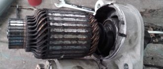
At the same time, the condition of all windings and the VAZ 2105 commutator is visually checked. If the last element heats up slightly, the plates are cleaned using sandpaper. In case of strong heating, the armature is replaced.
The next step is to dismantle the rubber seal and remove the adjusting washer. The assembly process involves installing this element in its place. The anchor is removed along with the drive. When removing the lever, you need to take into account that the gear must rotate freely in a certain direction. The worn part is replaced with a new one.
Assembly of the unit is carried out in reverse order. The limiter is put on the shaft towards the stopper ring. To do this, use a hammer and a key set to “14”. An important point is to blow dust out of the VAZ 21053 starter. To lubricate the parts, use “Litol-24” or grease No. 158. The following parts are lubricated with engine oil:
- bearing,
- sleeve,
- armature splines,
- hub.
Removing and installing the starter
The starter on a Niva rarely has to be changed, but if you have a need for this, the instructions below will be very useful. First, it’s worth considering the necessary list of tools with which doing all this will be very simple and will not take much time.
- Key for 13
- Ratchet with small extension
- Head for 10
Detailed guide to replacing the starter on Niva VAZ 2121
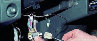
- First of all, open the hood of the car and disconnect all the power wires from the starter structure. To do this, you will need to unscrew the nuts that secure the terminals with a 10mm head. It is impossible to get there with a regular wrench, so a ratchet with a head and an extension would be an ideal option. We feel for the terminal nuts with our hands and, using the ratchet handle, unscrew them one by one.
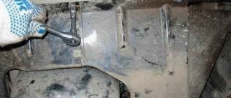
- To show everything clearly, look at the photo below; the key is inserted just under the Niva’s exhaust manifold:
- And after that, you can freely disconnect the power wires, which are not attached to anything else:
- Next, take a 13mm wrench, it’s more convenient to use a spanner, and unscrew the 2 bolts securing the starter housing to the engine. But there may be three of them; personally, in my example there were only 2.
- And then you can shoot it to the right, as clearly shown in the photo below:
- And turning it a little to the side, we take it out without any problems:
As you have seen for yourself, there is nothing complicated in this repair, the main thing is that you have all the necessary tools at hand and then any work on your Niva will be done quickly and without unnecessary nerves.
We install the VAZ 2121 starter in the reverse order of removal. If necessary, we replace it with a new part.
Location of relay blocks and their purpose
The fuse block (hereinafter referred to as the fuse block), unlike traditional models of the domestic automobile industry, is located in the vehicle interior. In particular, it is located on the driver's side under the steering wheel.
If any electrical circuit element in a car stops working (lamps, interior lights, heater, power windows), then car owners first check the power supply elements.
As a rule, the problem is resolved by replacing the fuse.
What does the power supply circuit itself look like? This question may be of interest to Niva owners. Below we will look at the electrical circuit of the unit with a description of all the components responsible for the operation of certain devices in the car.
In accordance with the diagram, we will consider the meaning of the BP elements. This electrical circuit is universal for all Niva cars.
It should also be noted that in VAZ 21214 injector cars there is another power supply unit with injection system components. It is located separately from the main power supply on the left side under the steering wheel.
In the case of the first described power supply unit, if the elements of the device begin to fail, this will in no way threaten the performance of the car, of course, with the exception of breakdowns of some components. However, in the case of the second power supply, if at least one component shorts out and does not work, the VAZ 21214 injector engine will not start.
If any electrical circuit in the vehicle fails, the condition of the fuse must be checked.
If it is necessary to replace parts, it should be taken into account that the VAZ 21214 fuses on the Niva injector belong to two different types:
- in the main block there are cylindrical inserts (inherited from the Zhiguli);
- and in the injection system blocks - modern, knife type.
Therefore, when you go on a trip, you need to take with you spare inserts of different types.
If, for example, a cigarette lighter fails on the road, you must:
- Turn off the ignition.
- Open the cover of the additional unit.
- Visually check the condition of the PR14 16 ampere fuse, which is responsible for the cigarette lighter circuit.
- Remove the burnt insert with your fingers and replace it with a spare one taken from the reserve socket PR15. It is prohibited to use homemade inserts, as they are not able to protect the circuit from overloads. The consequence of this may be overheating of the elements and fire.
- Check the functionality of the circuit. If the insert immediately burns out again, then the reason lies in damage to the wiring, which must be carefully checked.
The remaining fuses and relays on the VAZ 21214 are changed using a similar scheme.
In case of burnout or mechanical damage, it is necessary to repair the unit by replacing its components or the entire assembly.
To replace the main unit, follow these steps:
- Disconnect the battery from the on-board network.
- Remove the box cover and unscrew the two 8 mm nuts securing the block. Then you need to pull the box towards you and remove it from the fastening studs.
- Write down the markings and position of the wires on the old unit.
- Disconnect the cables from the plugs of the old unit and connect them in the same sequence on the new one.
- Check fuse ratings and wire installation.
- Secure the replaced block with nuts.
- Connect power to the on-board network and check the functionality of the circuits.
The photo shows some stages of dismantling the block.
Unscrewing fasteners
Removal from studs
Disconnecting the wiring plugs
Other fuse or relay blocks on the VAZ 21214 are replaced in the same way.
Below we will look at the process of replacing the power supply with your own hands. To replace, you will need a new power supply and a socket head set to “8”.
- First, open the hood and disconnect the battery.
- Now, under the instrument panel, find your power supplies. Using an “8” socket wrench, unscrew the two main nuts.
- Having done this, pry up the power supply and remove them from the studs.
- If you are replacing an old component with a new one, you must mark all the wires before doing so. Or take a new power supply unit and insert the wires from the old unit into it one by one. To remove the idle wires, pull them by their plugs.
- To check the functionality of the new power supply, reconnect the battery.
If any electrical circuit fails, the first thing you need to do is check the condition of the fuses and relays. This simple operation can be performed independently. The driver needs to know where the Niva Chevrolet fuse box is located and the purpose of the fuse links installed in it.
To protect electrical circuits on cars, fuses are used, located in a special mounting block. On a Chevrolet Niva VAZ 2123, this block is located inside the instrument panel, to the left of the plastic steering column cover.
In addition to the main unit, the Chevrolet Niva has an additional unit that is responsible for the operation of the car’s engine. This safety element is located in the passenger compartment and is located on the right side of the instrument panel behind the glove box.
The placement of blocks in the cabin is the same for cars of all years of manufacture.
The main blocks of machines are divided into two types - before 2009 and after. These devices are not interchangeable. The blocks behind the glove box are identical in design.
On a 2005 car, you can easily install a block from a 2011 car. The designation of the fuse rating is marked on the body; on the assembly itself there is a number of the fuse link and a pictogram of the purpose.
There are no fuse markings on the main unit cover.
The principle of operation of any standard relay in a car is the closure or switching of two contacts on a power electrical circuit using an electromagnetic field. Closing the contacts directly through the switch will require the use of thick wires and will lead to a voltage drop in the entire on-board network.
A typical fuel pump relay 75.3777-10 has 4 contacts, a coil with an armature, and a spring for opening the contact. When voltage is applied to the control contacts, the rod is drawn into the winding and another pair of contacts is closed. It turns off automatically as soon as the low-current connectors are de-energized.
Advantages of using relays in Niva Chevrolet cars:
- spontaneous leakage current in the on-board system is eliminated;
- reliable control of all electric motors;
- quick and guaranteed start of electrical mechanisms;
- Network overload protection.
The fuel pump relay has appeared on cars of the Chevrolet Niva family since 2003, when an injection engine was installed. The engines of the VAZ 21213 family are equipped with a carburetor and do not have a relay in the fuel supply system.
Electrical fuses on cars are changed if they blow out, without fail observing their rating. But other situations also happen on a VAZ 2121 Niva. For example, many motorists complain that sometimes electrical fuses simply fall out of the block. That is why it is recommended to replace the old unit with a new one, in which the safety elements hold up much better.
Also interesting: Generator Niva 2121, 21213, 21214: which one is installed, replacement
In the event of a breakdown, the fuses must be replaced in time to avoid serious problems with important components of the car in the future. The replacement process is quite simple. To do this, you simply need to remove the blown fuse and replace it with a new one.
Thus, further proper operation of the circuit for which he is responsible will be established. A very important nuance is the full compliance of the fuses (blown and new) regarding their markings and the output voltage. Otherwise, if this aspect is not taken into account, any of the elements included in the circuit that this fuse protects may burn out.
As a result, it must be said that the fuse is one of the most important parts in any car and Niva-21214 is no exception. In this regard, it is recommended to constantly monitor the condition of the mounting block and fuses. After all, if their work proceeds without any failures, then the risk of any serious electrical malfunction is reduced to almost a minimum.
Each of the fuses (FC) is responsible for a separate element of the vehicle's electrical circuit. In the main block, the numbering goes from left to right. There are 16 elements in total: 10 in the top row and 6 in the bottom.
Description of the upper section:
- Rear wiper motor, fluid supply to the front window, heater fan motor.
- Turn signals, reverse indicator, switches under the steering wheel, instrument panel and indicator lights.
- High beam (left headlight), indicator on the dashboard for turning on the high beam.
- High beam (right headlight).
- Low beam (left headlight).
- Low beam (right headlight).
- Dimensions (left side), license plate lighting, indicators on the instrument panel for turning on the dimensions.
- Dimensions (right side), instrument panel lighting.
- Hazard signal relay and power button, heated rear window.
- Brake lights, interior lighting, horn.
All fuses except the first have a rated current of 8A (PR1 - 16A). The bottom row is responsible for the following:
- Storage of 8A inserts
- Similar to the previous one.
- Rear fog lights.
- Cigarette lighter.
- Storage of 16A insert.
- Same for 8A.
The next power supply is responsible for the operation of the engine. The fuse diagram for Niva 21213 assumes 5 positions, and VAZ 21214 with an installed ABS system - 7 (positions 5-7 are responsible for it). The circuit without ABS looks like this:
- Start the electric fan motor on the right (30A).
- A similar position for the left side.
- Injection system control, injection nozzles, ignition coil, fan relay (15A).
- System for reducing the toxic component of gases, sensor of air supplied to the internal combustion engine (15A).
- Connector for diagnosing the operation of the injection system.
Note. Keep in mind that the location and purpose of fuses has changed and continues to change, depending on the year of manufacture and modification of the car. This page presents several options, be careful!
- Rear wiper motor, fluid supply to the front window, heater fan motor.
- Turn signals, reverse indicator, switches under the steering wheel, instrument panel and indicator lights.
- High beam (left headlight), indicator on the dashboard for turning on the high beam.
- High beam (right headlight).
- Low beam (left headlight).
- Low beam (right headlight).
- Dimensions (left side), license plate lighting, indicators on the instrument panel for turning on the dimensions.
- Dimensions (right side), instrument panel lighting.
- Hazard signal relay and power button, heated rear window.
- Brake lights, interior lighting, horn.
- Storage of 8A inserts
- Similar to the previous one.
- Rear fog lights.
- Cigarette lighter.
- Storage of 16A insert.
- Same for 8A.
- Start the electric fan motor on the right (30A).
- A similar position for the left side.
- Injection system control, injection nozzles, ignition coil, fan relay (15A).
- System for reducing the toxic component of gases, sensor of air supplied to the internal combustion engine (15A).
- Connector for diagnosing the operation of the injection system.
- On the left under the dashboard is block 1 under the first set of fuses. Here are the relays for the Niva 21214 fuel pump, ignition, main switch and both electric fans.
- To the right of the steering column, the relay block is responsible for the fog lights, heated rear window of the trunk door and both types of light (two elements for high and low beam).
- Above the second block are the hazard warning and turn signal relays.
- The starter relay on Niva 21214 is designed for several hundred amperes and is installed in the engine compartment.
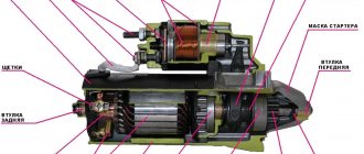
Starter problems and their elimination
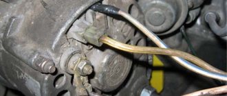
If the traction relay clicks and the car does not start, then the culprit of the situation is most often not the starter, but a discharged battery. Its charge is not enough to start the power plant. In addition, the problem may be hidden in oxidized contacts or damaged wires.
The weak point of the unit is the power wire loop connecting the electric motor and the traction relay. It does not connect securely to the terminal and is prone to oxidation and rot. If it breaks, the starter does not turn, despite the fact that a characteristic click of the traction relay is heard from the engine compartment.
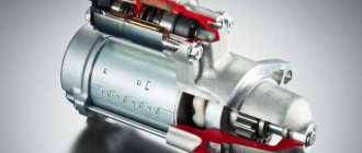
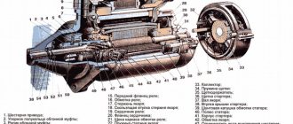
Design and operation
Read
The starter on the VAZ 2110 is designed in such a way that it contains a traction relay , which ensures the rotational movement of the drive gear. It starts when it engages the teeth of the crankshaft flywheel. That is, if the retractor device is faulty, then the engine will not start.
In addition, it is the traction winding that, when the contacts are closed, is designed to provide power to the starter motor from the battery. When the contacts close, the interlocks are activated and the pull-in winding is turned off.
The solenoid relay directly from the ignition switch and also serves to protect the starter. But since it consumes a lot of current, over time reliable contact disappears in the contact group.