Algorithm of actions during installation
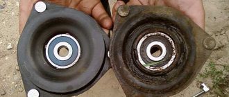
Now you can start replacing the shock absorbers; if the manufacturer’s recommendations indicate bleeding, be sure to do so.
Place a new boot and bump stop on the rod of the replaced strut. An important point: when installing, do not forget to put the gasket on the stand, which is located under the spring. You can remove it from the old rack if it is in satisfactory condition, or buy a new one. Then put the spring on the body, do it carefully and carefully, the lower and upper turns should coincide with the grooves. Place a support cup on top and secure it with a nut.
Loosen the ties on the spring and lower it into the corresponding grooves, insert the pins into the special holes and tighten them with the springs. During the assembly process, carefully inspect the transverse stabilizer; if it is loose, then its rubber bushings need to be replaced. Now screw the rack onto the lower supports, secure the wheel and remove the car from the jack, having first removed the stands. After this, tighten the nut on the rod and studs.
That's all, the process of replacing shock absorbers is completed, now you are convinced that it is not very difficult. Now repeat the manipulations on the second side of the car. The Hyundai Getz car does not have a camber adjustment process provided by the factory, so we will omit this point. Accordingly, if installed with serviceable components, no additional problems will arise. It is worth noting that we did not change the steering rack length, so the wheel alignment will remain the same as it was before the replacement.
Please note that shock absorbers are always changed in pairs so that the car behaves equally on each wheel (front or rear) while driving. This way you will protect yourself from the risk of getting into an accident.
↑ Elements of the front suspension of the VAZ 2106
- 1 – hub bearings;
- 2 – hub cap;
- 3 – nut;
- 4 – steering knuckle axle;
- 5 – cuff;
- 6 – hub;
- 7 – brake disc;
- 8 – protective cover of the upper ball pin;
- 9 – upper ball pin;
- 10 – bearing (liner) of the upper support;
- 11 – upper lever;
- 12 – compression stroke buffer;
- 13 – spring insulating gasket;
- 14 – shock absorber;
- 15 – shock absorber mounting pad;
- 16 – axis of the upper arm;
- 17 – rubber bushing of the hinge;
- 18 – outer bushing of the hinge;
- 19 – adjusting washers;
- 20 – suspension cross member;
- 21 – stabilizer bar cushion;
- 22 – stabilizer bar;
- 23 – axis of the lower arm;
- 24 – lower arm;
- 25 – clip for fastening the stabilizer bar;
- 26 – spring;
- 27 – rubber bushing of the shock absorber spring;
- 28 – lower spring support cup;
- 29 – steering knuckle;
- 30 – lower ball pin race insert;
- 31 – lower support bearing;
- 32 – lower ball pin.
The front suspension is independent, double wishbone, with a coil spring, telescopic hydraulic shock absorber and anti-roll bar.
Upper and lower arms
The axis of the lower arms is secured with two bolts to the cross member, which in turn is attached to the front side members. Between the axle and the cross member, two packages of spacer washers and shims are installed, which set the angles of longitudinal and transverse inclination of the front wheel turning axis.
The axis of the upper arms is a bolt passing through the mudguard strut. The levers on the axles rotate on rubber-metal hinges. The steering knuckle is attached to the arms on ball joints. A wheel hub with a brake disc is mounted on the steering knuckle axle on two tapered roller bearings. The right wheel hub nut has a left-hand thread and is marked in the form of dots on the end.
Springs and shock absorbers
The front suspension springs are of a cylindrical type; their upper end rests against the mudguard strut through a support cup with a rubber gasket, and the lower end rests against the support cup of the lower arm.
The shock absorbers are located inside the springs and are attached by the rod to the body through rubber pads, and by the eye of the body to the lower arm through a rubber-metal hinge.
The anti-roll bar (spring steel torsion bar) is designed to reduce the lateral roll of the car when cornering. It is attached through rubber cushions with the central part to the front side members of the body, and the ends to the lower suspension arms.
The easiest way to replace front shock absorbers
This method is also called classic, for its simplicity and accessibility to any car owner. It can be used by both beginners and fairly experienced drivers. To change the front shock absorber in this way, you need to buy a special key in advance that is capable of holding the shock absorber rod.
Replacement procedure:
- The car is installed on a flat surface and the possibility of any movement is excluded. Open the hood and, holding the shock absorber rod with a new tool, unscrew the top nut.
- After this, unscrew the three nuts at the edges of the mount.
- Loosen the hub nut using a 30mm socket and a very long lever. Raise the car and remove the wheel. Now completely unscrew the hub nut and use a hammer and a wooden block to knock the CV joint out of the hub.
- Using a puller, remove the tie rod end and the tie rod itself. Unscrew to the hub. Unscrew all fastenings of the hub to the levers and dismantle it. After this, pull out the shock absorber, remove the spring from it and install it on a new element.
- Assembly occurs in reverse order.
Which shock absorbers should I choose for a VAZ?
So, we will devote our article today to shock absorbers, namely to the question of which shock absorbers are best to choose and install on your VAZ. The problem of choosing new shock absorbers does not arise too often, but due to the fact that not only comfort, but also controllability and our safety depend on this choice, the choice is quite serious and should be very conscious. Shock absorbers differ not only in manufacturer, but also in type - oil shock absorbers, gas-oil, adjustable.
We are unlikely to be interested in adjustable shock absorbers - this kind of shock absorbers are used on expensive cars and are controlled electronically, AvtoVAZ is still very far from such innovations, but with regards to the first two announced types - this is where we can discuss. It is especially important to choose the right quality shock absorbers, because they are usually subject to constant increased load, and the car’s handling also largely depends on their condition. After all, shock absorbers primarily dampen body vibrations that occur while the car is moving. Have you ever driven or at least been a passenger in a car with junk cars? Yes, to me, it feels like you’re driving on jelly, the car is swinging on springs like a “jack-in-the-box.” It's very scary to drive, it's uncontrollable. So, back to the choice of shock absorbers.
Gas-oil engines are an ideal solution for those who mainly drive on highways, because, thanks to their increased rigidity, they improve the handling and stability of the car on the highway, in corners, etc. The downside is that when driving on an uneven surface (and most of our roads are just an uneven surface, or worse, a washboard from the Soviet period), the car will shake quite a bit, so it won’t swallow bumps. Well, oil ones are just ideal for comfortable movement over rough terrain. My personal choice is the oil shock absorbers that our VAZs are equipped with from the factory. Regarding the manufacturer, it’s better to scour the specialized forums. Some people are 100% satisfied with the factory SAAZ, some are satisfied with the quality of FENOX (although many argue that the quality of spare parts of this brand is a lottery). Personally, my VAZ-2107 had Phenox front calipers and a pump, all without any complaints. They skated a lot. Many people prefer HOLA, but the one with the most good reviews is, of course, KYB Exel-G. I had BOGE shock absorbers (oil) - in my opinion, they were ideal. In general, food for thought has been provided, the final choice is yours, and we are ready to answer all your questions on our forum or in our VKontakte group! Until next time.
How to understand that shock absorbers are already faulty
Experienced motorists themselves are able to determine the condition of the chassis. They observe how the car behaves on the road and draw the appropriate conclusion. This is quite easy to notice; a car with sagging shock absorbers above 70 km/h begins to skid along the road. Moreover, when you drive over a hole or bump, you hear a characteristic knock, this sound comes specifically from the chassis.
You can also check the condition of the shock absorbers yourself. It is enough to be near the car. The procedure is as follows: you need to press on any edge of the body to the limit, for example, on the rear. After this, sharply release, a working shock absorber of the car should quickly and smoothly raise the body. But what if the body has risen to the maximum upper point and begins to fall down, in other words, just swaying? In this case, bad news awaits you: your car requires replacing the rear shock absorbers.
An external inspection of the chassis is just as effective. A bent rod or oily smudges will tell you that the system is already worn out and requires repair.
Replacing shock absorbers VAZ 2107
Faulty shock absorbers of the “seven” can be replaced independently. For this you will need:
- set of wrenches;
- jack;
- wheel wrench;
- screwdriver.
To access the rear shock absorbers, you need to install the car on a lift or pit; the front ones can be changed even without them.
Change the shock absorbers one by one (first on one side, then on the other). Procedure for replacing front shock absorbers:
- jack up the car and remove the wheel;
- open the hood and unscrew the nut securing the rod to the body bowl;
- unscrew the two shock absorber mounting nuts on the lower arm;
- pull the shock absorber down, squeezing it;
- install a new shock absorber;
- tighten the nuts securing the shock and the lower part;
- install the wheel and lower the jack.
To replace the rear shock absorbers, you need to unscrew the nuts and remove the upper and lower mounting bolts (often you have to clean the threads and use WD-40 to do this). New shock absorbers are installed in place of the old ones.
Didn't find the information you are looking for? on our forum.
Signs of Damper Failure
At speeds above 30 km/h, driving a car without shock absorbers is very problematic. Working parts are designed to control the wheel: it makes one movement up, one movement down, and the remaining energy (about 80%) is absorbed by the damper, turning into heat and dissipating in the air.
Properly functioning shock absorbers ensure safety, but not everyone is aware of this fact.
. The units wear out gradually, and this process is not accompanied by symptoms. The driver ignores the fact that his car has begun to behave differently - the result is an accident.
The ABS and Traction Control systems do not recognize faulty shock absorbers. Their sensors record the movement of the wheels along the track, and not their rotation in the air. As a result, the electronic control unit receives incorrect data and incorrectly transmits instructions to other mechanisms. Therefore, when determining the serviceability of dampers, the driver is forced to rely on his own feelings. The main signs of a breakdown are a decrease in ride comfort, the appearance of vibrations, and also the fact that the car begins to “knock.”
To bleed the rack do the following:
1. With the stand in a vertical position, smoothly pull the rod to its highest point, then smoothly return it back.
It is necessary to make 3-4 such movements, during execution you should not feel any failures, falls or jamming of the rod. After pumping the racks, keep them in a vertical position until they are installed in place. It is necessary to pump the racks in order to bring them into working condition.
Now you can begin assembling the new shock absorber
1. Set the rack rod to the upper position.
- Carefully place the boot and compression buffer onto the new strut.
- Install the spring, then the cup and damper.
- Install the smaller washer from the kit, as well as the larger one, then the support along with the bearing.
- We tighten the rod fastening nut.
- Tighten the nut using a hexagon to “6” and use it to hold the rod. The final tightening is done already on the car, that is, after the front pillar is in place.
- The zip ties can be removed.
8. Turn the support with the pointer forward and slightly inward of the car body.
- Now you can actually install the new Acomi stand in place.
- Tighten the upper support bolts, then place the strut on the steering knuckle. Install an eccentric bolt with a washer in the upper hole, and a regular bolt in the lower, and then “pull” everything properly.
- Install the tie rod pin into the rod on the strut, then tighten the nut.
- Pin your finger.
- Install the brake hoses into the holder bracket on the rack.
All is ready! Replacing the front strut was successful, all that remains is to put the wheel in place and lower the jack. After lowering the car to the ground, once again go through all the fasteners with the wrench and tighten the nuts until they stop.
Perform all the above steps on the other side. As a rule, the second time things are “more fun”, because the second time you already have some experience, it seems like your hand is “full” or something...
And lastly, after you have replaced the front struts of your Lada Priora, be sure to go to a service station and get a wheel alignment done. If this is not done, you may have problems, because the wheels are not adjusted, the car will “drive” from side to side, so it’s better not to risk it.
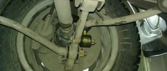
Replacing the front suspension of a VAZ 2106
Planned replacement of the front suspension of the VAZ 2106 or its individual components is carried out after the overhaul life of the unit or its elements has expired, and unscheduled repairs are carried out as necessary. The operation is carried out in the following order:
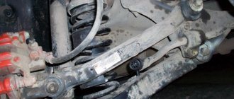
We drive the “six” onto an overpass or other technical place. Having fixed the upper cut of the shock absorber rod with a holder, unscrew its upper fastener
Next, we hang the front end on the stops and dismantle the front wheelset. Having bent the stopper with a screwdriver, we unscrew the brake caliper fastener to the mount, and then move it to the non-working area so as not to damage the brake hoses. We dismantle the shock absorber struts, then unscrew the edges of the front suspension stabilizer from the mounts of the levers located below. Using a special device, we press the fingers out of the technological holes of the suspension arms and remove the steering rods into the non-working area. Using a special device that acts like a clamp, we compress the spring and secure it in a compressed state. We dismantle the axes of the upper and bottom arms along with other elements of this unit, after which we take out the spring element and carry out similar actions with the other side of the “six” suspension. We dismantle the engine mudguard and stabilizer console. Holding the power unit with the lifting mechanism, we dismantle the front suspension cross member, acting very carefully. We install all front suspension components in the opposite order. To get rid of the incorrect concentration of impacts on rubber-metal type hinges, we tighten the lever fasteners. We place the vehicle on a horizontal area and install the front wheel pair coaxially with the direction of travel “straight”. We carry out the maximum load of the “six” - about 3200 N (about 4 people in the cabin and 50 kg in the luggage compartment). Sequentially tighten the fasteners of the upper and lower front suspension arms and the fasteners of the lower linkage to the cross member using a torque wrench. We monitor and, if necessary, set the turning angles of the front wheels. The standard front suspension of the VAZ 2106, a video on replacing which can be viewed on the Internet, is also subject to repair work
High-quality repairs of the front suspension are carried out only after assessing the technical condition of the vehicle
The standard front suspension of the VAZ 2106, a video on how to replace it can be viewed on the Internet, is also subject to repair work. High-quality repairs of the front suspension are carried out only after assessing the technical condition of the vehicle.
Maintenance (MOT) and repair of the front suspension of the VAZ 2106 consists of the following technological processes: adjusting the correct clearance values of the wheel bearings; changing oil seal gaskets and carrying out lubrication work; changing front suspension shock absorbers, as well as spring elements, silent blocks, lever mechanisms, stabilizer bar and cushions under it, ball bearings, etc.
After completing the repair work on the VAZ 2106 suspension, it is necessary to carry out adjustment measures to adjust the installation angles of the front wheel pair. If there is a need to purchase components of this unit for repair work, then the front suspension of the VAZ 2106, the price of which together represents a fairly large amount, is sold in many auto parts stores.
As for tuning the VAZ 2106 suspension, you should pay special attention to it. First of all, you should replace the standard springs and shock absorber struts by installing completely different products that cause a change in suspension clearance
Next, it is recommended to install a double-type front stabilizer, and for the body part to mount different braces to increase the rigidity coefficient of this load-bearing element.
Does the camber of wheels on a VAZ change when installing supports under the front pillars?
Yes, both camber and toe change, it is necessary to adjust.
Front suspension assembly: 1 — upper support of the telescopic strut; 2 — upper support cup; 3 — compression stroke buffer assembled with a protective casing; 4—compression buffer support; 5 — suspension spring; 6 — lower spring support cup; 7 — steering rod ball joint; 8 — steering knuckle; 9 — telescopic stand; 10 - eccentric washer; 11 — adjusting bolt; 12 — rack bracket; 13 — steering knuckle; 14 — front brake protective cover; 15 — brake disc; 16 — retaining ring; 17 — wheel hub cap; 18 — splined shank of the wheel drive joint housing; 19 — guide pin; 20 — wheel hub bearing; 21 - ball joint; 22 — suspension arm; 23 — adjusting washers; 24 — stabilizer strut; 25 — stabilizer bar; 26 — stabilizer bar cushion; 27 — stabilizer bar mounting bracket; 28 — body bracket
Telescopic stand: 1 — compression valve body; 2 — compression valve discs; 3 — throttle disk of the compression valve; 4 — compression valve plate; 5 — compression valve spring; 6 — compression valve cage; 7 — recoil valve nut; 8 — recoil valve spring; 9 — recoil valve plate; 10 — recoil valve disc; 11 — throttle disk of the recoil valve; 12 - piston; 13 — bypass valve plate; 14 — bypass valve spring; 15 - plunger; 16 — plunger spring; 17 — rod guide bushing with a fluoroplastic layer; 18 — guide bushing cage; 19 — sealing ring of the rack housing; 20 — rod seal; 21 — oil seal cage; 22 — gasket of the rod protective ring; 23 — rod protective ring; 24 — nut of the strut housing; 25 — compression buffer support; 26 — rod; 27 — spring cup; 28 — rotary lever; 29 — rod limit sleeve; 30 — rack body; 31 - cylinder; 32 - drain tube
Shock absorbers VAZ 2101 Zhiguli
- Repair manuals
- Repair manual for VAZ 2101 (Zhiguli) 1970-1985.
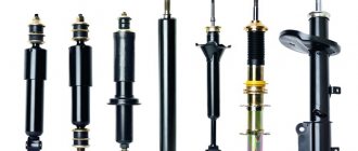
- Shock absorbers
Shock absorbers front and rear suspensions
| 1 – lower eye; 2 – compression valve body; 3 – compression valve discs; 4 – throttle disk of the compression valve; 5 – compression valve spring; 6 – compression valve cage; 7 – compression valve plate; 8 – recoil valve nut; 9 – recoil valve spring; 10 – shock absorber piston; 11 – recoil valve plate; 12 – recoil valve discs; 13 – piston ring; 14 – recoil valve nut washer; 15 – throttle disk of the recoil valve; 16 – bypass valve plate; 17 – bypass valve spring; 18 – restrictive plate; 19 – reservoir; 20 – rod; 21 – cylinder; | 22 – casing; 23 – rod guide bushing; 24 – sealing ring of the tank; 25 – rod seal race; 26 – rod seal; 27 – gasket of the rod protective ring; 28 – rod protective ring; 29 – tank nut; 30 – upper shock absorber eye; 31 – nut securing the upper end of the front suspension shock absorber; 32 – spring washer; 33 – shock absorber mounting pad washer; 34 – pillows; 35 – spacer sleeve; 36 – front suspension shock absorber casing; 37 – rod buffer; 38 – rubber-metal hinge |
The shock absorbers of the front and rear suspensions differ in size, the method of fastening the upper part and the presence of a recoil buffer 37 at the front shock absorber, which limits the shock absorber travel during the recoil stroke.
In addition, the front shock absorber has different performance parameters. The rear shock absorber consists of a reservoir 19 with an eye, a compression valve (items 2, 3, 4, 5, 6, 7), a working cylinder 21, a rod 20 with a piston 10 and recoil and bypass valves, and a casing 22 with an eye.
Reservoir 19 is made of a steel pipe, to the lower end of which eye 1 is welded, and in the upper part a thread is cut for nut 29. The compression valve body 2, assembled with valve discs, is inserted into the recess of the eye. It is pressed against the recess by working cylinder 21. The annular space between the reservoir and the cylinder is filled with liquid. Inside the working cylinder there is a rod 20 with a piston 10. The piston has vertical channels located in two circles. The channels on the small circle are closed from below by discs 12 and 15 of the recoil valve, and on the larger circle - from above by disc 16 of the bypass valve.
The compression valve is located at the bottom of the cylinder. In the valve body 2 there is a socket, to which a spring 5 is pressed through a plate 7, disks 3 and 4. The throttle disk 4 has a cutout through which the liquid is throttled at a low speed of movement of the piston. In the lower part of the valve body there is a cylindrical groove and four vertical channels, and in the cage 7 there are six side holes and one central hole, through which the liquid passes from the reservoir to the cylinder and back.
A guide sleeve 23 is installed on top of the cylinder, which is sealed in the reservoir with a ring 24, and the output of the rod is sealed with an oil seal 26 with a holder 25. All parts located in the upper part of the cylinder are tightened with a nut 29, which has four holes on top for a special key.
Rubber-metal hinges 38 are pressed into the shock absorber eyes.
Checking shock absorbers on a stand
Shock absorber operating diagram
| 1 – force during recoil; | 2 – force during compression stroke |
To determine the performance of the shock absorber, check its operating diagram on a dynamometer.
Take operating diagrams according to the instructions supplied with the stand, after performing at least 5 working cycles, at a temperature of the shock absorber working fluid of 20±5° C, a flywheel rotation speed of 1 s–1 (60 min–1) and a rod stroke length of 80 mm for the front shock absorber and 100 mm for the rear.
The curve of the diagram should be smooth, and at the transition points (from the recoil stroke to the compression stroke) there should be no sections parallel to the zero line.
Evaluation of results using the diagram. The resistance of the recoil and compression strokes is determined by the largest coordinates of the corresponding diagrams.
The highest point of the recoil stroke curve at a scale of 47 N (4.8 kgf) per 1 mm should be from the zero line at a distance A equal to: 21–28 mm for front shock absorbers, 19–26 mm for rear shock absorbers.
The highest point of the compression stroke curve at the same scale should be located from the zero line at a distance B equal to: 3.5–6.5 mm for front shock absorbers; 4.5–7.5 mm – for the rear.
The control values of the ordinates on the diagrams of the front and rear shock absorbers are specified for cold shock absorbers at a shock absorber fluid temperature of 20±5° C.
After checking, remove the shock absorber from the stand and, if necessary, reassemble and replace damaged parts.
Repeat the test to ensure the shock absorber is working properly.
↓ Comments ↓
1. Technical data
1.0 Technical data 1.1 Main overall dimensions of the VAZ-2101 car 1.2 Main overall dimensions of the VAZ-21011 car 1.3 Main overall dimensions of the VAZ-2102 car 1.4 Technical characteristics of the cars 1.5 Controls and monitoring devices 1.6 Ignition switch 1.7 Interior ventilation and heating controls
2. Operation and Maintenance
2.0 Operation and maintenance 2.1. Vehicle operation 2.2. Vehicle maintenance
3. Engine
3.0 Engine 3.1 Features of the device 3.2 Possible engine malfunctions, their causes and methods of elimination 3.3 Removing and installing the engine 3.4 Disassembling the engine 3.5 Assembling the engine 3.6 Bench tests of the engine 3.7 Checking the engine on a car 3.8. Cylinder block 3.9. Pistons and connecting rods 3.10. Crankshaft and flywheel 3.11. Cylinder head and valve mechanism 3.12. Camshaft and its drive 3.13. Cooling system 3.14. Lubrication system
4. Fuel system
4.0 Fuel system 4.1. Power system 4.2. Carburetor
5. Ignition system
5.0 Ignition system 5.1 Setting the ignition timing 5.2 Gap between the breaker contacts in the ignition distributor 5.3. Checking ignition devices on a stand 5.4 Possible ignition malfunctions, their causes and methods of elimination
6. Starting and charging system
6.0 Starting and charging system 6.1. Battery 6.2. Generator 6.3. Starter
7. Transmission
7.0 Transmission 7.1. Clutch 7.2. Gearbox 7.3. Cardan transmission 7.4. Rear axle
8. Chassis
8.0 Chassis 8.1. Front suspension 8.2. Rear suspension 8.3. Shock absorbers 8.4 Possible malfunctions of the chassis, their causes and methods of elimination
9. Steering
9.0 Steering 9.1 Features of the device 9.2. Inspection, check and adjustment of steering 9.3. Steering mechanism 9.4. Steering rods and ball joints 9.5. Pendulum arm bracket 9.6 Possible steering malfunctions
10. Brake system
10.0 Brake system 10.1. Features of the device 10.2. Checking and adjusting brakes 10.3. Clutch and brake pedal bracket 10.4. Main cylinder 10.5. Front brakes 10.6. Rear brakes 10.7. Rear brake pressure regulator 10.8. Parking brake 10.9 Possible brake malfunctions, their causes and methods of elimination
11. Electrical equipment
11.0 Electrical equipment 11.1. Electrical circuit diagrams 11.2. Lighting and light signaling 11.3. Sound signals 11.4. Windshield wiper 11.5. Heater electric motor 11.6. Control devices
12. Body
12.0 Body 12.1 Features of the device 12.2. Repair of the body frame 12.3. Paint and varnish coatings 12.4. Anti-corrosion protection of the body 12.5. Doors 12.6. Hood, trunk lid, bumpers 12.7. Body glazing and windshield washer 12.8 Instrument panel 12.8. Removal and installation 12.9. Seats 12.10. Heater
13. Features of repair
13.0 Features of repair 13.1. Car VAZ-21011 13.2 Cars VAZ-21013 13.3. Car VAZ-2102 13.4 Cars VAZ-21021 and VAZ-21023
14. Applications
14.0 Appendices 14.1 Tightening torques for threaded connections 14.2 Tools for repair and maintenance of vehicles 14.3 Used fuels, lubricants and operating fluids 14.4 Basic data for adjustments and control
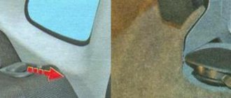
Front pillar repair
You can repair and bleed the front strut yourself, but you need to buy a new oil seal and seal ring, they are sold as a repair kit. You also need to purchase a spindle oil to pump the oil rack. Gas shock absorbers in the struts are not pumped, they are disposable and not dismountable, they are replaced entirely with new ones.
Photo. We knock down the limiter support.
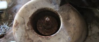
Photo. It is shown how to unscrew the nut of the strut housing with a bit.
I won’t explain all the intricacies of disassembling the front strut, because just be careful and you yourself will understand where everything is, and you can easily change the oil seal and O-ring. But if the strut rod has severe scuffing, then it must be replaced with a new one.
Photo. The insides of the strut, the arrow shows the oil seal and the O-ring, which must be changed when bleeding the oil strut.
I pour oil into the shock absorber of the strut like this, insert the shock absorber into the strut and lower the rod down, fill the oil up to the threads, and without pulling the shock absorber out of the strut, lift the rod, and again add oil, assemble the strut, but do not tighten it, then lower the rod and the excess oil is squeezed out, But I don’t lower the rod all the way, I leave it about twenty millimeters, and I tighten it. After such bleeding, the strut shock absorber works great.
Rear shock absorbers for VAZ 2106 - 2101
The rear wheel struts are also the same, not divided into right/left. They also have several articles, all interchangeable. The characteristics of the rear shock absorbers can be compared with the front ones. The only difference is that it is not felt as much on the rear axle, since the rear is lighter.
To improve the situation using domestic components, many Zhiguli owners install rear shock absorbers, also from Niva, but from VAZ 2121. Also, in order to raise the rear a little, they often install springs from Niva, and shock absorbers from Moskvich 2140.
| Dimensions of rear original shock absorbers for VAZ 2101 - 2106 | |||||
| vendor code | Rod diameter, mm | Case diameter, mm | Body height (excluding stem), mm | Rod stroke, mm | price, rub. |
| 2101-2915402-02 2101-2915402-04 | 12,5 | 41 | 306 | 183 | 600 |
Analogs of rear shock absorbers 2101 – 2106
Since almost no one installs originals on the rear wheels, below is a list of the most popular substitutes.
| Manufacturer | vendor code | price, rub. |
| KYB | 443123 (oil) | 1000 |
| KYB | 343098 (gas-oil) | 1250 |
| Fenox | A11001C3 | 600 |
| SS20 | SS20180 | 3400 (set of 2 pieces) |
KYB 343098
SS20180
What shock absorbers are best to buy for a classic Lada? The most frequently purchased and popular vehicle for the VAZ 2101 – 2106 family is traditionally Kayaba (KYB). They are stiffer than stock (especially gas ones), and more comfortable. But the disadvantage is the high price. The most optimal budget option is Belarusian Fenox shock absorbers.
Racks from the Russian SS20 are just gaining popularity, but they certainly deserve attention. In terms of rigidity, they can be compared with Kayaba (gas). They absorb road imperfections very well, especially at high speeds.
Shock absorbers on VAZ 2101 - 2106 need to be changed depending on their condition. The original ones last an average of 50 thousand km. Although in many cases this figure differs by an order of magnitude. Sometimes the original shock absorber begins to leak at 20 thousand km, and sometimes more than 100 thousand km pass. This is another reason why analogues are usually preferred.
Front shock absorbers VAZ 2101 – 2106
The shock absorbers of the front wheels on Zhiguli are not divided into left and right. The original contains several articles. But these are all the same shock absorbers, and they are interchangeable. Regarding the characteristics of the front shock absorbers specifically on the classic Zhiguli, here their softness is especially strongly felt. When hitting even small bumps, the heavy front sways well, which makes being in the cabin not very comfortable.
| Dimensions of original front shock absorbers for VAZ 2101 - 2106 | |||||
| vendor code | Rod diameter, mm | Case diameter, mm | Body height (excluding stem), mm | Rod stroke, mm | price, rub. |
| 2101-2905402 2101-2905402-02 2101-2905402-04 | 12 | 41 | 217 | 108 | 500 |
Many experienced drivers advise installing original SAAZ Niva shock absorbers on the front wheels, and more specifically from VAZ 21214. They are stiffer and more stable on uneven surfaces and speeds above 80 km/h.
Replacement front shock absorbers for Zhiguli 2101 – 2106
Analogs for domestic cars of the Zhiguli family are more in demand. The reasons why originals are not often played are described above. The most popular replacements for front shock absorber struts, which are actually most often installed on VAZs, will also be listed here.
Replacement of front shock absorbers VAZ 2107, VAZ 2106
So, we drive the car into a pit or overpass, put wheel chocks under the wheels and put the hand brake on.
Open the hood and unscrew the upper part of the shock absorber using a seventeen key, take out the washer and rubber cushions of the shock absorber photo 1.
Now we crawl under the car and turn the lower part of the shock absorber, which is attached to the lower arm using the bracket photo 2, with a wrench to thirteen.
To make it easier to unscrew the nuts, clean the threads with a metal brush, and preferably spray them with WD-40 penetrating lubricant.
Then we pull it down. We unscrew the bracket that is attached to the bottom of the shock absorber ear.
The installation is carried out as follows: you need to extend the rod to its full length and insert the shock absorber through the hole in the lever.
If you have an assistant, ask him to place the nut on the rod on top, after inserting new rubber cushions of the shock absorber.
This is done so that the rod does not fall back down, which is why you simply cannot tighten the top nut later. Then tighten the bottom nuts. On the other side we do the same thing. This completes the replacement of VAZ 2107 shock absorbers. Have a good trip.
Hello, in this article you will learn how to replace the front shock absorbers on a VAZ 2101, 2102, 2103, 2104, 2105, 2106, 2107 in a garage. The average mileage of front shock absorbers without replacing them is about 40,000 km, sometimes more, sometimes less, it depends on the driving style. If you drive all the time on bad roads, also at high speed, then the shock absorbers can be “killed” even in 20,000 km. Failure of the shock absorber entails worse and unsafe handling, greater swing and an increase in the braking distance. Before a shock absorber fails, oil leaks and fogging usually appear; if all the oil leaks out of the shock absorber, it may generally jam in one position. Shock absorbers are replaced in pairs, not one at a time. The average price of one front shock absorber is approximately 1000 rubles. To replace the front shock absorbers you will need wrenches 6, 13 and 17. First of all, open the hood and hold the shock absorber rod with a wrench 6, unscrew the nut on the shock absorber rod with a wrench 17
Remove the nut, washer and cushions from the shock absorber. Next, take a 13 mm wrench or socket and unscrew the 2 nuts that secure the front shock absorber bracket
The next step is to remove the shock absorber along with the bracket downwards
Now unscrew the bolt securing the bracket to the shock absorber and move the bracket to the new shock absorber. Installing the front shock absorber is done in the reverse order. We perform the same operation with the second shock absorber.
Avtochanel
Sources
- https://remont-vaz2106.ru/vaz-2105-zamena-perednix-amortizatorov
- https://remontavtovaz.ru/vaz-2107/instrukciya-po-zamene-perednix-amortizatorov-vaz-2107.html
- https://www.avtochanel.ru/remont/snyatie-i-zamena-perednih-amortizatorov-na-vaz-2101-2102-2103-2104-2105-2106-2107.html
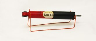
Gas-oil front suspension shock absorber ASOMI SPORT (-50 mm) VAZ 2101-2107 (2 pieces)
APPLICABILITY: VAZ 2101, 2102, 2103, 2104, 2105, 2106, 2107.
Installed with lowered springs -50 mm or -70 mm.
Shock absorbers "ASOMI" SPORT series
VAZ 2101-2107
cars have a gas-filled (gas-oil) design, a shortened body and a shortened rod stroke. They are ideal for lovers of an aggressive driving style.
Shock absorbers SPORT series
for “classics” they have an increased dimension (rod with a diameter of 14 mm, cylinder - 30 mm, reservoir - 45 mm) and higher resistance forces during the compression and rebound strokes compared to standard shock absorbers. These changes made it possible to ensure the necessary energy intensity of the shock absorbers to effectively dampen vehicle vibrations with shortened suspension strokes, which significantly increases the vehicle's controllability and stability in all driving modes, including at high speed and when making sharp turns.
Technical feature of ASOMI
for
VAZ 2101-2107 SPORT series
- this is a shortened body and a shortened rod stroke, which allows them to be installed
with lowered springs -50 mm or -70 mm
.
In turn, the “gas boost” in shock absorbers with a shortened rod stroke ensures more stable operation of the valves, significantly reducing fluid foaming, and adds elastic compression characteristics to the car’s suspension. However, in normal vehicle operation, the SPORT
have fairly comfortable characteristics.
Advantages of SPORT series shock absorbers:
— effectively dampen vibrations of the body and wheels when the vehicle is moving;
— reduce car roll when making sharp turns;
— provide high stability and controllability of the car at high speeds;
— guarantee safety when driving fast;
— increased service life.
located in the city of Togliatti, the capital of the automotive industry. This is a modern enterprise that occupies a leading position in the development and production of improved automotive suspension components.
The group was founded in 1997, starting its activities with the sale of equipment, materials and tools for vehicle maintenance and repair.
In 2002, the company's activities shifted towards the creation of new suspension components, brake system components and steering parts. For this purpose, the research and production association “AUTOPUSVESKA” was formed, which became an engineering association.
Today it produces a wide range of improved automotive suspension components under the ASOMI (supports, struts, shock absorbers, springs, front and rear suspension assemblies, anti-roll bars, hinges) for VAZ cars - Lada Samara, Lada 2110 and Lada Kalina , Chevrolet Niva and other car brands.
High quality and improved product characteristics guarantee comfort, reliability, safety when driving a car, and also provide an increased service life of the car suspension as a whole.
In the production of products, we use progressive design solutions, advanced automotive technologies and modern equipment, without which the technical development of our company is not possible. Pre-production samples and prototypes, developed by engineers and designers, go through the stages of three-dimensional parametric design and modeling using CAD software. Improving vehicle performance and maximizing customer satisfaction is the main result of the work of our specialists.
Thanks to professionalism, technological experience, an innovative approach to work and the active life position of its employees, it does not stop at the achieved results and continues to move forward.
Includes: 2 shock absorbers.
Replacing front shock absorbers on VAZ-2108-099, 2110-2115
As for the VAZ-2108-099 cars, as well as the 2110 family, replacing their front shock absorbers is somewhat more complicated.
This is due to the fact that the shock absorber strut also acts as a steering knuckle.
But it is quite possible to replace shock absorbers yourself, although you will need more tools:
- Special socket wrench 22;
- Powerful flat screwdriver;
- Special key for holding the shock absorber rod;
- Keys for 19 (2 pcs.);
- Key to 27;
- Ball joint remover;
- Special ties for springs;
- Hammer;
- Wooden tip;
- WD-40;
- Marker.
On these cars, work begins in the engine compartment. But before this, the car is placed on the pit, and the side from which it is being made is jacked up and the wheel is removed.
Use a screwdriver to pry off the rubber plug securing the upper support. Then, using a 22mm spanner, unscrew the nut securing the rod, while it is held in place with its own special wrench.
At this point, work at the top stops and moves down.
Before disconnecting the strut from the hub, you first need to remove the tie rods.
To do this, you need to unscrew the tip fastening nut, and then use a puller to press the tip itself out of its seat in the rack.
To disconnect the strut from the hub, you need to unscrew the fastening nuts with 19mm wrenches and pull out the bolts.
But keep in mind that the top bolt is an adjustment bolt, so you need to mark its position before loosening it. During assembly, this will help to at least approximately determine the camber angle.
Often these bolts fit very tightly in the holes, so after unscrewing the nuts, they may need to be knocked out.
This is where a hammer with a wooden handle comes in handy so as not to damage the bolt threads.
Once the bolts are removed, it will be possible to lower the hub down and free the lower end of the strut. In this case, you need to monitor the tension of the brake pipe.
Having freed the bottom of the pillar, work again moves into the engine compartment.
The final step in removing the rack will be to unscrew the three fastening nuts using a 13 key on the upper support.
After this, it will be possible to remove the rack down.
But this is not the end of the work, since the shock absorber itself still needs to be removed from the strut.
This will require the use of spring ties. By placing them opposite each other on the spring, the spring is evenly compressed.
To remove the support and be able to remove the shock absorber, you need to hold the rod with a special wrench and unscrew the nut securing the cushion with a 27 wrench.
Next, the support, rod protective casing and bump stop are removed from the rod.
Then the shock absorber is removed from the strut.
A new one is placed in its place and the rack is assembled in the reverse order.
When installing the rack in place, it is important not to forget to align the marks on the adjusting bolt. After complete assembly, you will need to check the tightness of all connections again.
This element is replaced on the other side in the same way.
After complete assembly, you will need to check again the tightness of all connections. This element is replaced on the other side in the same way.
And then it is imperative to go to the nearest service station to perform a wheel alignment adjustment.
8.3.1 Shock absorbers
Shock absorbers front and rear suspensions
| 1 – lower eye; 2 – compression valve body; 3 – compression valve discs; 4 – throttle disk of the compression valve; 5 – compression valve spring; 6 – compression valve cage; 7 – compression valve plate; 8 – recoil valve nut; 9 – recoil valve spring; 10 – shock absorber piston; 11 – recoil valve plate; 12 – recoil valve discs; 13 – piston ring; 14 – recoil valve nut washer; 15 – throttle disk of the recoil valve; 16 – bypass valve plate; 17 – bypass valve spring; 18 – restrictive plate; 19 – reservoir; 20 – rod; 21 – cylinder; | 22 – casing; 23 – rod guide bushing; 24 – sealing ring of the tank; 25 – rod seal race; 26 – rod seal; 27 – gasket of the rod protective ring; 28 – rod protective ring; 29 – tank nut; 30 – upper shock absorber eye; 31 – nut securing the upper end of the front suspension shock absorber; 32 – spring washer; 33 – shock absorber mounting pad washer; 34 – pillows; 35 – spacer sleeve; 36 – front suspension shock absorber casing; 37 – rod buffer; 38 – rubber-metal hinge |
The shock absorbers of the front and rear suspensions differ in size, the method of fastening the upper part and the presence of a recoil buffer 37 at the front shock absorber, which limits the shock absorber travel during the recoil stroke.
In addition, the front shock absorber has different performance parameters. The rear shock absorber consists of a reservoir 19 with an eye, a compression valve (items 2, 3, 4, 5, 6, 7), a working cylinder 21, a rod 20 with a piston 10 and recoil and bypass valves, and a casing 22 with an eye.
Reservoir 19 is made of a steel pipe, to the lower end of which eye 1 is welded, and in the upper part a thread is cut for nut 29. The compression valve body 2, assembled with valve discs, is inserted into the recess of the eye. It is pressed against the recess by working cylinder 21. The annular space between the reservoir and the cylinder is filled with liquid. Inside the working cylinder there is a rod 20 with a piston 10. The piston has vertical channels located in two circles. The channels on the small circle are closed from below by discs 12 and 15 of the recoil valve, and on the larger circle - from above by disc 16 of the bypass valve.
The compression valve is located at the bottom of the cylinder. In the valve body 2 there is a socket, to which a spring 5 is pressed through a plate 7, disks 3 and 4. The throttle disk 4 has a cutout through which the liquid is throttled at a low speed of movement of the piston. In the lower part of the valve body there is a cylindrical groove and four vertical channels, and in the cage 7 there are six side holes and one central hole, through which the liquid passes from the reservoir to the cylinder and back.
A guide sleeve 23 is installed on top of the cylinder, which is sealed in the reservoir with a ring 24, and the output of the rod is sealed with an oil seal 26 with a holder 25. All parts located in the upper part of the cylinder are tightened with a nut 29, which has four holes on top for a special key.
Rubber-metal hinges 38 are pressed into the shock absorber eyes.
Checking shock absorbers on a stand
Shock absorber operating diagram
| 1 – force during recoil; | 2 – force during compression stroke |
To determine the performance of the shock absorber, check its operating diagram on a dynamometer.
Take operating diagrams according to the instructions supplied with the stand, after performing at least 5 working cycles, at a temperature of the shock absorber working fluid of 20±5° C, a flywheel rotation speed of 1 s–1 (60 min–1) and a rod stroke length of 80 mm for the front shock absorber and 100 mm for the rear.
The curve of the diagram should be smooth, and at the transition points (from the recoil stroke to the compression stroke) there should be no sections parallel to the zero line.
Evaluation of results using the diagram. The resistance of the recoil and compression strokes is determined by the largest coordinates of the corresponding diagrams.
The highest point of the recoil stroke curve at a scale of 47 N (4.8 kgf) per 1 mm should be from the zero line at a distance A equal to: 21–28 mm for front shock absorbers, 19–26 mm for rear shock absorbers.
The highest point of the compression stroke curve at the same scale should be located from the zero line at a distance B equal to: 3.5–6.5 mm for front shock absorbers; 4.5–7.5 mm – for the rear.
The control values of the ordinates on the diagrams of the front and rear shock absorbers are specified for cold shock absorbers at a shock absorber fluid temperature of 20±5° C.
After checking, remove the shock absorber from the stand and, if necessary, reassemble and replace damaged parts.
Repeat the test to ensure the shock absorber is working properly.
Which stands are better?
Many times I have heard car enthusiasts argue which struts are better, some praise oil struts, others double-acting gas struts, and interestingly, each in his own way is right.
Now let’s figure out which struts are better, oil or gas. But first I’ll explain the difference between oil and gas struts. The oil strut works like this: it easily responds to compression without resistance, and comes out tightly back. The gas strut rests a little when compressed and comes out hard back.
In order for you to decide on the choice of rack for your car, and decide which rack will be better, I will give an example.
The gas strut behaves great on the highway, because due to its low compression rigidity it confidently holds the car on the highway, but as soon as you go on a grader or off-road, the car turns into a rattle. And all because the gas strut does not absorb small bumps well, due to its resistance to compression.
The oil rack is much softer, which is why the car may not feel very confident at high speed, on the highway, but it works great on graders and off-road, which greatly increases the comfort of driving on such roads.
Now I think you have decided on the choice of racks for your car, and have decided which racks are better.
I decided for myself, since I often have to drive off-road, that I installed oil struts, but before that, on gas ones, the car rattled like a rattle.
Replacing the front suspension springs of a VAZ 2106 - detailed instructions
- While the car is “on wheels”, tear off the wheel mounting bolts with a “balloon”.
- Jack up the car with a screw jack on the side where you are going to change the suspension spring.
- Next, you need to hang the wheel and completely remove it from the car.
After this, remove the shock absorber, this is done as follows:
- To do this, use the key at "6, 13, 17 and 19".
- The rod must be kept from turning with a key.
- Next, loosen the nut and remove it.
- Also remove the cushion washer, spring washer and upper shock absorber mounting pad.
8. Unscrew the two fastening nuts of the bracket to the lever and remove the spring washers.
9. Remove the shock absorber from the bottom using the mounting hole in the arm.
10. Loosen the mounting nuts that secure the lower arm to the axle, but do not rush to remove them.
Now it’s the turn of the second jack (hydraulic)
11. Place it under the lower control arm, then raise it slightly to load the suspension and level the lower control arm.
12. Remove the stabilizer bar.
13. Unscrew the nuts of the stabilizer bracket and remove the bracket with the rubber cushion.
14. Unscrew the nut that holds the pin in the ear of the steering knuckle, but now you can remove the lower ball joint.
15. Lower the jack and knock out the support pin with a hammer; to do this, hit the lower ear of the steering knuckle several times.
16. With the lower ball joint removed, reinstall the jack under the lower control arm, but there is now no need to load the suspension.
17. After this, you can unscrew the ball joint pin nut completely, slowly, and carefully lower the lower arm down. Help yourself with a mounting spatula by moving the stabilizer to the side so that it does not catch the bracket mounting studs.
18. Now completely unload the suspension and move the jack to the side.
19. Prepare a strong rope or wire, with its help you need to pull the upper arm as high as possible in order to provide yourself with access to the front suspension spring.
20. Take a pry bar and use it to pry the lower end of the spring, then carefully remove it from the lower arm support cup.
21. Remove the suspension spring, remove the spring gasket from the upper support cup.
Now that nothing is in the way, the front suspension spring can be replaced.
To replace the front spring, do the following:
1. Take a new spring, attach a gasket to it (use regular electrical tape for this) and install it in place.
2. Install the mounting blade into the hole for the shock absorber and, holding the spring with it, fix the lower coil. By looking at the surface of the lower arm, you can see a helical surface indicating the correct position of the spring. Helping yourself with mounting, you need to adjust the correct position of the spring in relation to the screw surface.
3. Having set the correct position of the lower coil, install the jack under the lever and create a load on the spring, then use a mounting blade to finally seat the spring on the screw surface.
4. Increase the load on the spring and, using a mounting tool, install the stabilizer bar into a position between the two mounting studs of the stabilizer bracket.
Assembly is carried out in reverse order.
Now we can say that the replacement of the front suspension springs of the VAZ 2106 has been completed.
Features of shock absorbers
Features of shock absorbers
Repair and operation manual - VAZ-2101 chassis - VAZ-2107 - Features of shock absorbers
Features of shock absorbers
Front and rear suspension shock absorbers
1 – lower eye; 2 – compression valve body; 3 – compression valve discs; 4 – throttle disk of the compression valve; 5 – compression valve spring; 6 – compression valve cage; 7 – compression valve plate; 8 – recoil valve nut; 9 – recoil valve spring; 10 – shock absorber piston;
11 – recoil valve plate; 12 – recoil valve discs; 13 – piston ring; 14 – recoil valve nut washer; 15 – throttle disk of the recoil valve; 16 – bypass valve plate; 17 – bypass valve spring; 18 – restrictive plate; 19 – reservoir; 20 – rod; 21 – cylinder; 22 – casing; 23 – rod guide bushing; 24 – sealing ring of the tank; 25 – rod seal race; 26 – rod seal; 27 – gasket of the rod protective ring; 28 – rod protective ring; 29 – tank nut; 30 – upper shock absorber eye; 31 – nut securing the upper end of the front suspension shock absorber; 32 – spring washer; 33 – shock absorber mounting pad washer; 34 – pillows; 35 – spacer sleeve; 36 – front suspension shock absorber casing; 37 – rod buffer; 38 – rubber-metal hinge.
The shock absorbers of the front and rear suspensions differ in size, the method of fastening the upper part and the presence of a recoil buffer 37 at the front shock absorber, which limits the shock absorber travel during the recoil stroke. In addition, the front shock absorber has different performance parameters.
The rear shock absorber consists of a reservoir 19 with an eye, a compression valve (items 2, 3, 4, 5, 6, 7), a working cylinder 21, a rod 20 with a piston 10 and recoil and bypass valves, and a casing 22 with an eye.
Reservoir 19 is made of a steel pipe, to the lower end of which eye 1 is welded, and in the upper part a thread is cut for nut 29. The compression valve body 2, assembled with valve discs, is inserted into the recess of the eye. It is pressed against the recess by working cylinder 21. The annular space between the reservoir and the cylinder is filled with liquid. Inside the working cylinder there is a rod 20 with a piston 10. The piston has vertical channels located in two circles. The channels on the small circle are closed from below by discs 12 and 15 of the recoil valve, and on the larger circle - from above by disc 16 of the bypass valve.
The compression valve is located at the bottom of the cylinder. In the valve body 2 there is a socket, to which a spring 5 is pressed through a plate 7, disks 3 and 4. The throttle disk 4 has a cutout through which the liquid is throttled at a low speed of movement of the piston. In the lower part of the valve body there is a cylindrical groove and four vertical channels, and in the cage 7 there are six side holes and one central hole, through which the liquid passes from the reservoir to the cylinder and back.
A guide sleeve 23 is installed on top of the cylinder, which is sealed in the reservoir with a ring 24, and the output of the rod is sealed with an oil seal 26 with a holder 25. All parts located in the upper part of the cylinder are tightened with a nut 29, which has four holes on top for a special key.
Rubber-metal hinges 38 are pressed into the shock absorber eyes. Drawings of a device for replacing the silent blocks of the front and rear shock absorbers.
Checking shock absorbers on a stand
Shock absorber operating diagram
1 – force during recoil; 2 – force during the compression stroke.
To determine the performance of the shock absorber, check its operating diagram on a dynamometer.
Take operating diagrams according to the instructions supplied with the stand, after performing at least 5 working cycles, at a temperature of the shock absorber working fluid of 20±5° C, a flywheel rotation speed of 1 s–1 (60 min–1) and a rod stroke length of 80 mm for the front shock absorber and 100 mm for the rear.
The curve of the diagram should be smooth, and at the transition points (from the recoil stroke to the compression stroke) there should be no sections parallel to the zero line.
Evaluation of results using the diagram. The resistance of the recoil and compression strokes is determined by the largest coordinates of the corresponding diagrams.
The highest point of the recoil stroke curve at a scale of 47 N (4.8 kgf) per 1 mm should be from the zero line at a distance A equal to: 21–28 mm for front shock absorbers, 19–26 mm for rear shock absorbers.
The highest point of the compression stroke curve at the same scale should be located from the zero line at a distance B equal to: 3.5–6.5 mm for front shock absorbers; 4.5–7.5 mm – for the rear.
The control values of the ordinates on the diagrams of the front and rear shock absorbers are specified for cold shock absorbers at a shock absorber fluid temperature of 20±5° C.
After checking, remove the shock absorber from the stand and, if necessary, reassemble and replace damaged parts.
Repeat the test to ensure the shock absorber is working properly.
Quote
Muffler tuning
The exhaust system of VAZ cars of the “classic” series (2101–2107) consists of three parts: the exhaust pipe (“pants”), a resonator and a muffler.
Direct-flow muffler: device, advantages, installation
Many owners of “kopecks” do not leave the exhaust system of their cars without improvements, replacing the standard muffler with a direct-flow muffler, or simply adding it to an existing one, achieving the “double exhaust” effect and the characteristic low roar that accompanies it.
What is the difference between a straight-through muffler and a regular muffler? A standard muffler consists of numerous sharply curved baffles and tubes. Passing through them, exhaust gases are forced to change directions, which is why the pressure drops, the sound becomes quieter, and toxicity decreases.
In a direct-flow muffler, the pipes, as the name suggests, are straight, the bends are smoothed, there are no partitions, and there are fewer welds. This allows exhaust gases to move freely.
In a direct-flow muffler, exhaust gases encounter almost no resistance on their way out, which means they do not lose pressure, etc.
A ready-made ramjet engine can be purchased at a spare parts store; This pleasure will cost one and a half to three thousand rubles. Most models can be installed without welding. However, some craftsmen make direct-flow mufflers on their own, using old undamaged mufflers and pipes, or limiting themselves to only the latter.
Video: do-it-yourself direct-flow muffler
When a penny needs new pants
The exhaust pipe of the VAZ 2101 was called “pants” for its characteristic design: two long pipes connected at the edges resemble trouser legs.
The exhaust pipe received the name “pants” for its characteristic shape.
It is necessary to replace the intake pipe when a through hole forms in it and it begins to leak air. The fact is that exhaust gases circulate through the pipe, the temperature of which can reach 300–500 degrees, which over time even damages metal.
In addition, the “penny” needs to change its “pants” if the intake pipe is deformed.
The pipe is located under the bottom of the car in the front part.
To replace the exhaust pipe on a VAZ 2101, you need the following tools:
- wrench “13” (preferably an extension with a socket head of the appropriate size);
- universal joint;
- calipers;
- metal ruler.
Important point: replacement should only be done when the engine is cool; otherwise, there is a risk of getting burns - after all, as mentioned above, the pipes in the exhaust system can heat up to several hundred degrees.
To replace the exhaust pipe, you need:
- Disconnect or completely remove the rear muffler.
- Disconnect the resonator from the exhaust pipe and remove it.
- Using a wrench, unscrew the bolt securing the clamp that secures the pipe to the bracket on the box.
- Under the hood, unscrew the four nuts that secure the pipe to the exhaust manifold.
- Carefully remove the exhaust pipe with both hands.
Installation is carried out in reverse order.
Thus, with a little time and money, you can not only improve the technical characteristics of your car, but also give it an individual, unique look. Read more about all the methods of tuning the VAZ 2101 on our website.
Car suspension and our roads
When driving, the car suspension absorbs all vibrations from the road surface and dampens them, excluding the transfer of the latter to the vehicle body.
Of course, it is impossible to completely damp out vibrations, given the state of our roads, but the suspension still absorbs most of them. In this case, the main work in damping vibrations is performed by the shock absorber.
But due to constant heavy loads, this element may fail.
All this will be accompanied by a decrease in controllability, increased body vibration, and knocking when hitting large bumps.
The manifestation of these signs indicates the need to replace shock absorbers.
While shock absorbers have not been created that can work forever, you can, of course, install devices from KYB KAYABA, but they also do not last forever.
Therefore, over time you will have to change them, regardless of what car they are installed on - an old “penny” VAZ-2101 or a Lexus LX570.
But not so many people own Lexus cars, but there are a lot of VAZ owners, and most of them prefer to repair their cars themselves.
Therefore, let's look at how to replace front shock absorbers on different VAZ models - from the Classic to the VAZ-2110 family.
How to check if shock absorbers on struts need to be replaced
One of the easiest, cheapest and most effective ways to check dampers is a visual inspection. You may notice oil mist on the part, which should not be there. Lubricant leaks are a sign of depressurization and a signal that it’s time to change the component
. If doubt arises during inspection, the shock absorber should be wiped clean and checked again after a few days of operation. They also look at the anthers and rebound buffer. Oil can contribute to the destruction of these parts.
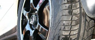
An important step is to inspect the tires. If signs of wear are visible, especially uneven wear, then we can safely say that the dampers are faulty. You also need to check the stem of the part. If scratches from clamps or corrosion are noticeable on its surface, the shock absorber requires urgent replacement.
Traces of corrosion on the shock absorber rod indicate the need for urgent replacement of the part.
The most common is the car sway test. You can determine which shock absorber has failed by pressing on the corner of the car: where the part is faulty, the car will continue to oscillate. If the damper “stands up”, this indicates that it is jammed. It is advisable to carry out this test regularly
.
Visual inspection of the vehicle's shock absorbers for faults
The vehicle's directional stability is also checked. At a speed of more than 80 km/h, the car begins to “scour” along the road, especially if there are uneven spots and holes on the road surface. The car's stability decreases.
Stands for instrumental diagnostics of dampers are of two types: vibration and test. When using the first type of stand, the car is driven onto a special platform, which, after a few minutes of testing, produces a diagram of axial vibrations. Experts, based on the data obtained and normal parameters for a particular model, determine the condition of the shock absorbers.
Checking car shock absorbers on a vibration stand
The second option involves completely disassembling the car’s suspension and removing parts. As a result of such actions, the most accurate information is collected, but such a procedure will cost a pretty penny. Bench testing of depreciation load is carried out mainly for diagnosing expensive components.
During bench testing, the shock absorber is disassembled into parts