Adjusting Renault Duster door locks
Adjusting the door locks is necessary if the doors open and close too tightly, or vice versa, if they do not close tightly enough and the rear edge of the door protrudes beyond the outer elements of the body. It should be borne in mind that such malfunctions can be associated not only with incorrect adjustment of the door lock, but also with other reasons: play in the door hinges due to wear, deformation of the hinges, deformation of the door itself and even the entire body. To clarify the reasons, it is necessary to remove the lock lock.
Comment
The work is performed similarly on the front and rear doors.
We carry out the work in the following order:
1. We prepare the car for maintenance and repair.
2. Mark the position of the front door lock latch so that you can return to the original settings.
4. Close the door tightly and check the gaps around its perimeter. If the door has sagged, we try to lift its back part. If the door can be moved upward, the hinges are worn out. The misalignment of the door in the opening is caused either by deformation of the frame of the door itself or by deformation of the load-bearing elements of the body. In any case, body repair is required (you may have to contact a specialized service station to fix the problem).
5. If the closed door in the opening is located evenly, the gaps around its perimeter are uniform, install the lock latch in place and screw it in without completely tightening it.
Auto parts for foreign cars, auto repair
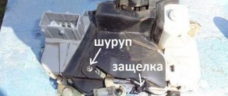
I will only say that to access the lock you do not need to remove the glass of the door, but only need to unscrew the glass guide bar, having first pulled out the rubber band from it.
Having gained access to the lock, I still decided not to remove it, but with my left hand try to place the rod for opening the external handle into its sockets - yes, I didn’t say that the rod fell out of its sockets even when leaving the lock on the Renault Logan external door door handles.
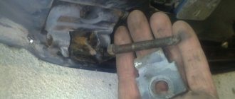
Then I saw with the help of a special mirror with a flashlight and felt by touch that my rod had broken due to the breakage of the plastic retainer securing it to the lock mechanism.
I tried unsuccessfully for half an hour to pull out a piece of the old latch from the socket with my fingernails - unsuccessfully... Having assessed the situation and the time the sun was already close to sunset, I decided to completely remove the lock, which helped me not to remove a piece of the stuck old latch from the Renault Logan door lock, but also to insert a new one into the socket a latch from Asam, which I could not insert without removing the lock... Having placed the rod in its sockets, we first attach it through a plastic latch to the removed lock and check its movement by pressing the outer door handle.
Then we assemble the Renault Logan door lock elements in the reverse order. The result... The result is wonderful - everything works, the problem is fixed.
In addition, I cleaned the removed lock from dirt and lubricated it thoroughly. It was also discovered that the upper nut securing the window lifter mechanism was missing, and this was already a full-fledged “cricket” - I immediately installed a new one from my spare parts case.
Thank God for everything! Now I’m thinking of inspecting the lock of the left rear door, which periodically “growls” at me when closing... As it turned out, everything is extremely simple, and the reason for blocking the door from the inside was apparently accidentally touched by the “children’s” door lock flag... Now I will have a lock on the door Renault Logan in the trunk a couple of Asam things... God grant everyone good luck and a Guardian Angel on the way!
We bring the guide through the technological hole in the inner panel of the door... ...and remove the lower glass guide. By pressing the plastic lock of the rod 1 of the outer handle, turn it around its axis and disconnect the rod from the lock.
In the same way we disconnect the rod of the 2nd cylinder lock mechanism. We turn the rod of the lock lock button so that the protrusion on the rod fits into the slot of the lock... ...and remove the rod with the button.
Use a screwdriver to pry up the wire block retainer... ...and, having disconnected the wire block, remove the lock assembly with the electric drive.
If necessary, disconnect the rod of the internal door opening handle from the lock and remove the electric drive of the lock. These operations are similar to the corresponding operations shown on the rear door lock, see Install the front door lock in the reverse order.
To remove the outer front door handle, remove the lower glass guide and disconnect the outer door handle rod from the lock, see Fig.
Attempted hijacking of Renault Logan
Basically, our Laboratory protects from theft new cars worth over 800,000 rubles, most of which top the theft ratings.
Choosing a brand, hours on the Internet studying characteristics and offers, reading forums, trips to a car dealership, down payment, waiting, full payment (or confirmation of a loan), insurance, registration and obtaining license plates. If you want to keep the car, and not hope to get part of its value by running around with certificates, adding money and going through the purchasing rounds again, then the car needs to be protected from theft.
Removing the front door lock and outside handle
We carry out the work when replacing the lock and external handle. The operations are shown on the driver's door. The lock and handle of the right door are removed in the same way. Remove the door trim (see “Removing the front door trim of Renault Logan”).
Using a Torx T-30 wrench, unscrew the screw securing the lower glass guide.
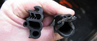
Remove the glass seal from the guide.
We bring the guide out through the technological hole in the inner panel of the door...
...and remove the lower glass guide.
By pressing the plastic lock of the rod 1 of the outer handle, turn it around its axis and disconnect the rod from the lock.
In the same way we disconnect the rod of the 2nd cylinder lock mechanism.
We turn the rod of the locking button so that the protrusion on the rod fits into the slot of the latch...
The rear door on a Renault Logan does not open from the inside. Options? | Topic author: Svetlana
Tatyana, listen to the man, don’t go into the depths, don’t dig a hole for yourself. Open the door, move the lever to another position and that’s it, it’s small, at the end of the door right under the lock. You can see it and you won’t confuse it. It will help interestingly, otherwise maybe there is something else there, if it’s not difficult, then tell me whether we are right or wrong
Oksana I had such trouble on the 12th. So it turned out that everything was banally simple - under the lock itself at the end of the door there is a “switch”, it just had to be lifted up. A special feature was made so that children would not open the door on the go.
How to replace the front door lock cylinder of Renault Logan
To complete the work, you will need the same tools as for removing upholstery and pliers.
- Raise the glass and remove the front door trim.
Unfasten the lock switch rod clamp and disconnect the rod from the lock lever.- Using pliers, grab the bent edge of the spring clamp of the cylinder and remove the clamp.
- We take out the lock cylinder along with the rod from the hole in the outer panel of the door
- If you are changing the lock cylinder, you need to disconnect it from the lever and install a new one.
- Reinstall everything in reverse order. Before installation, you need to lubricate the cylinder with silicone grease.
Video on the topic:
Yamaha diversion 600 reviews
Pros Excellent ergonomics. Acceptable acceleration dynamics. Good brakes. Excellent handling at all speeds. Small price. Cons Noisy clutch operation. The motorcycle was produced only for European and…
Recently, when closing the front passenger door, a metallic knock began to be heard. Having carefully looked at the lock latch on the body, I realized that it needed to be adjusted.
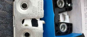
1. To unscrew the lock lock we need a TORX T40 key. Unscrew and remove the lock. I unscrewed it very easily (and on all the doors, I’ll say right away that the slight tightening of it served to displace it, that is, the reason for the door closing in such a way)
2. Close the door tightly and check the gaps around the perimeter: the door should not “sag” or warp in the opening. If the door sag, the hinges are worn out, the skew means deformation of the door itself or the frame. I read in someone’s blog that if you add a little isolette, the closing sound is somewhat softer. I decided to use heat shrink.
Brake system Features of the device Possible malfunctions of the brake system, their causes and solutions Bleeding the Renault Logan hydraulic drive Removing the rear door lock of the system Checking and adjusting the brake pedal Master brake cylinder Vacuum brake booster Brake force regulator in the hydraulic drive of the rear brakes Replacing hoses and pipelines of the hydraulic drive of the brakes Front brake mechanisms wheels Braking mechanisms of the rear wheels Parking brake Section Electrical equipment Design features Diagnosis of faults in on-board electrical equipment Mounting blocks Battery Generator Starter Ignition switch Engine control system Lighting, light and sound alarm Windshield wiper Removal and installation of the windshield washer Removal and installation of the electric motor of the radiator fan of the cooling system Renault Logan engine Removing the rear door lock of the rear window Removing and installing the cigarette lighter socket Instrument cluster Immobilizer Instrument panel switches Car audio system Replacing sensors and switches Section Squeeze the rod holder clamps, recess them inside the door and remove the holder.
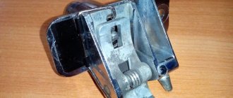
We unscrew the 3 screws securing the lock. We remove the lock through the technological hole in the door. Disconnect the wires from it.
The lock has been removed. By moving the front seats as far forward as possible, I prepared myself “space” for comfortable work.
I will only say that to access the lock you do not need to remove the glass of the door, but only need to unscrew the glass guide bar, having first pulled out the rubber band from it.
Having gained access to the lock, I still decided not to remove it, but with my left hand try to seat the opening rod of the external handle into its sockets - yes, I didn’t say that the Renault Logan removal of the rear door lock fell out of its sockets even when it failed external door handle.
Then I saw, with the help of a special mirror with a flashlight, and felt on Renault Logan removing the rear door lock, that my pull was broken due to the breakage of the plastic retainer securing it to the lock mechanism. I unsuccessfully tried for half an hour to pull out a piece of the old lock from the socket with my fingernails - unsuccessfully... Having assessed the situation and the time the sun was already close to sunset, I decided to completely remove the lock, which helped me not only pull out the piece of the stuck old lock, but also insert a new lock from Asam into the socket, which I could not insert without removing the lock... Having placed the rod in its sockets, we first attach it through a plastic retainer to the removed lock and check its movement by pressing the outer door handle.
We remove the electric lock assembly through the technological hole in the inner door panel. Having released the lock of the wire block, disconnect the block from the electric drive of the lock and remove the lock assembly with the electric drive.
We turn the electric drive so that the protrusion on the drive rod 2 fits into the slot 1 on the lock lever... ...and remove the electric drive.
Replacing the front door lock and adjusting it
The left and right doors have a similar arrangement of parts. Before disassembly, the electric drive phase is turned off and a set of equipment is prepared. To remove the casing and get to the closing device you will need:
- wrench;
- open-end wrench;
- hammer;
- Silicone Grease;
- anti-corrosion substance;
- file;
- pliers;
- sharp knife;
- Screwdriver Set.
If there is no visual deformation of the door, then the cause of the breakdown should be sought inside the mechanisms. Analysis will show: it is necessary to completely replace the lock; it is enough to change the cylinder or carry out lubrication work. There are three main stages: removal of the facing panel, inspection of the mechanism, repair. The work is carried out from inside the car. Algorithm of actions:
- Disassembling the handle: removing plugs, bolts, lining.
- Removing the top row of panel clips.
- Disconnecting wiring.
- Removing the bottom row of plastic clips.
- Remove the panels and bolts that secure the lock.
- Disabling the latch, removing the locking ring, disconnecting the rod.
- Element removal, inspection.
- Cleaning the inner niche: removing dirt.
- Lubrication with silicone and anti-corrosion agent.
- Replacement of the cylinder or the entire device. Activation of the mechanism.
Next, reassembly and adjustment are carried out, and the functionality of the element is checked. If the door has sagged or is slightly deformed, the adjusting bolts will need to be tightened or loosened. They are on the door pillar. The basic rule of adjustment: loosen or tighten, then fix the result.
Replacing the rear door lock Renault Logan 2004-2015
- Repair manuals
- Renault Logan 2004-2015
- Replacing the rear door lock
You will need: all the tools needed to remove the rear door trim and glass, as well as T30 and T40 TORX wrenches, and a flat-blade screwdriver.
| 1. Remove the rear door trim (see “Removing and installing the rear door trim”). |
| 2. Remove the rear door glass (see “Replacing the rear door glass”). |
| 3. Disconnect the outer handle rod from the lock lever by unfastening the rod lock and turning it to the side. |
| NOTE Disconnecting the outer handle rod is shown with the handle and lock removed for clarity. The inner door lock handle rod was disconnected while removing the rear door trim. |
| 4. Using a screwdriver, remove the axis of the lock drive rocker arm from the hole in the door panel. | 5. Turn the rocker 90° counterclockwise... |
| 6. ...and, having disconnected the locking drive rod from the rocker arm, remove the rocker arm together with the locking button rod. | 7. Remove the drive rods and locking rods from the holders on the inner door panel. |
| 8. Squeeze the rod holder clamps, push them inside the door and remove the holder. | 9. Remove the three screws securing the lock to the door panel. |
| 10. Having brought the lock into the technological hole in the door panel... | 11. ...disconnect the wiring harness block from it and remove the lock from the car. |
| 12. If you are changing the lock, disconnect the rods of the internal drive handle and lock from it by unfastening and turning their latches to the sides, and install them on the new lock. | 13. To remove the door lock latch, unscrew it from the body pillar. |
| NOTE The latch is tightened with a large torque, so we recommend using an impact screwdriver to loosen it. |
| 14. Install the rear door lock and all removed parts in the reverse order of removal. |
| NOTE If necessary, adjust the locking accuracy of the lock by moving the latch, loosening its tightening. |
↓ Comments ↓
Section 1. Vehicle design
General information about the vehicle Vehicle registration data Vehicle keys Controls Heating (air conditioning) and interior ventilation Doors Seat belts Seats Rear view mirrors Interior lighting Hood Gearbox control lever
Section 2. Recommendations for use
Safety rules and recommendations What you need to have in your car Running in the car Operating the car during the warranty period Preparing the car for departure
Section 3. Problems along the way
The engine will not start Malfunction of the fuel injection system Idle has disappeared Interruptions in the engine The vehicle moves jerkily The vehicle does not accelerate well The engine stalls while driving The oil pressure has dropped The engine is overheating The battery is not recharging The engine is started from external power sources Faulty electrical equipment Extraneous knocking noises Problems with the brakes Punctured wheel
Section 4. Maintenance
General provisions Daily maintenance (EO) First maintenance (MOT-1) Second maintenance (MOT-2)
Section 5. Engine
Design features Removing and installing mudguards and engine crankcase protection Replacing the suspension mounts of the power unit Installing the piston of the first cylinder to the TDC position of the compression stroke Replacing and adjusting the belt tension, replacing the tension roller of the gas distribution mechanism drive Adjusting the clearances in the valve drive Removing, installing and troubleshooting the flywheel Replacement engine seal parts Cylinder head Removal and installation of the engine Engine lubrication system Engine cooling system Exhaust system Power supply system
Section 6. Transmission
Clutch Gearbox Front wheel drives
Section 7. Chassis
Front suspension Rear suspension Checking and adjusting wheel alignment angles
Section 8. Steering
Design features Possible malfunctions of steering without hydraulic booster, their causes and methods of elimination Possible malfunctions of steering with hydraulic booster, their causes and methods of elimination Steering column Steering rods Steering mechanism
Section 9. Brake system
Features of the device Possible malfunctions of the brake system, their causes and solutions Bleeding the hydraulic drive of the brake system Checking and adjusting the brake pedal Master brake cylinder Vacuum brake booster Brake force regulator in the hydraulic drive of the rear brakes Replacing hoses and pipelines of the hydraulic brake drive Brake mechanisms of the front wheels Brake mechanisms of the rear wheels Parking brake
Section 10. Electrical equipment
Design features Diagnostics of malfunctions of on-board electrical equipment Mounting blocks Battery Generator Starter Ignition switch (lock) Engine control system Lighting, light and sound alarm Windshield wiper Removal and installation of the windshield washer Removal and installation of the electric motor of the radiator fan of the engine cooling system Electric heating of the rear window Removal and installation cigarette lighter socket Instrument cluster Immobilizer Instrument panel switches Car audio system Replacement of sensors and switches
Section 11. Body
Design features Possible body malfunctions, their causes and solutions Removal and installation of bumpers Removal and installation of radiator lining Removal and installation of wheel mudguards and fender liners Removal and installation of the front wing Hood Removal and installation of the air intake box grille Doors Trunk lid Removal and installation of the fuel filler hatch cover tank Seats Removal and installation of floor tunnel lining Passive safety system (SRS) Rear view mirrors Instrument panel Heater and air conditioner Interior fittings Removal and installation of interior linings Removal and installation of trunk lining Replacement of fixed body glazing Body care
Section 12. Wheels and tires
Technical characteristics Marking of rims Marking of tires Replacing wheels Tire break-in Tire storage Wheel balancing Snow chains Spare wheel Checking tire pressure Checking tire profile Checking valve Checking radial and lateral runout of rims
Section 13. Purchase of spare parts
Engine oil Lubricants Coolants Brake fluid Fuel filter Air filter Engine oil filter Spark plugs
Section 14. A trip to the service station
Section 15. Winter operation of the vehicle
How to prepare a car for winter Recommendations for starting the engine in severe frost What is useful to buy for winter Useful winter tips
Section 16. Preparation for technical inspection
Recommendations List of malfunctions and conditions under which the operation of vehicles is prohibited Changes to state standards regulating the maximum permissible content of harmful substances in the exhaust gases of motor vehicles
Section 17. Tips for a novice auto mechanic
Safety precautions when carrying out repair work Tools Before starting work Restoring threaded connections Tips for body repair
Applications
Appendix 1. Tightening torques of critical threaded connections, N m Appendix 2. Lamps used on a car Appendix 3. Spark plugs used on a car Appendix 4. Air pressure in tires
Electrical circuit diagrams
Diagram 1. Battery charging circuit: 1 – starter; 2 – generator; 3 – electrical wiring connector for the engine compartment/interior (monoblock); 4 – instrument cluster Diagram 2. Fuel pump and fuel level sensor: 1 – instrument cluster; 2 – electrical wiring connector for the engine compartment/interior (monoblock); 3 – electrical wiring connector for the instrument panel/left rear part of the body; 4 – fuel pump and fuel level sensor; 5 Diagram 3. Engine control system: 1 – 597V fuse box in the engine compartment (see Fig. 10.2a and 10.2b); 2 – relay block 784 in the engine compartment, relay 700 (see Fig. 10.2a and 10.2b); 3 – injector of the 1st cylinder; 4 – fuse box in the passenger compartment (see fig. 4. Engine starting system: 1 – battery; 2 – starter; 3 – engine compartment/cabinet electrical wiring connector (monoblock); 4 – ignition switch (lock) Diagram 5. Turn indicators and alarm system: 1 – interior switching unit; 2 – electrical wiring connector for the instrument panel/left rear part of the body; 3 – right rear light; 4 – right front turn signal; 5 – right indicator repeater Diagram 6. Side light: 1 – fuse box in the cabin (see Fig. 10.1); 2 – electrical wiring connector for the instrument panel/left rear part of the body; 3 – side light of the left headlight; 4 – left rear lamp; 5 – license plate lamp; 6 – Diagram 7. High beam : 1 – fuse box 597A in the engine compartment (see Fig. 10.2a and 10.2b); 2 – switch lever for external lighting and direction indicators with a button for turning on the sound signal; 3 – fuse box in the passenger compartment (see Fig. 10.1); 4 Diagram 8. Electrically heated rear window: 1 – fuse box in the passenger compartment (see. rice. 10.1); 2 – instrument cluster; 3 – electric heating of the rear window; 4 – electrical wiring connector for the instrument panel/left rear part of the body; 5 – electric heating switch for Scheme 9. Electric fan of the heating and ventilation system of the cabin: 1 – fuse box in the cabin (see Fig. 10.1); 2 – relay 233 (see Fig. 10.2a and 10.2b); 3 – wiring connector for the electric fan of the cooling system/instrument panel; 4 – electric fan Diagram 10. Front fog lights: 1 – instrument cluster; 2 – switch lever for external lighting and direction indicators with a button for turning on the sound signal; 3 – fuse box in the passenger compartment (see Fig. 10.1); 4 – relay block 299 in the engine compartment Diagram 11. Electric mirror drive: 1 – fuse block in the passenger compartment (see Fig. 10.1); 2 – control unit for external rear view mirrors; 3 – electric drive of the left outside rear view mirror with heating; 4 – electric drive of the right outside rear mirror Diagram 12. Low beam: 1 – fuse block 597A in the engine compartment (see Fig. 10.2a and 10.2b); 2 – switch lever for external lighting and direction indicators with a button for turning on the sound signal; 3 – fuse box in the passenger compartment (see Fig. 10.1); 4 Diagram 13. Front door power windows: 1 – front passenger door power window switch; 2 – electric motor for window lift of the front passenger door; 3 – driver’s door window lift motor; 4 – block before Scheme 14. Electric fan of the heating (air conditioning) system and interior ventilation: 1 – fuse box in the passenger compartment (see Fig. 10.1); 2 – relay 233 (see Fig. 10.2a and 10.2b); 3 – electrical wiring connector for the engine compartment/interior (monoblock); 4 – electric fan Diagram 15. Sound signal: 1 – lever of the switch for external lighting and direction indicators with a button for turning on the sound signal; 2 – fuse box in the passenger compartment (see Fig. 10.1); 3 – sound signal; 4 – fuse block 597A in the engine compartment (see Diagram 16. Central locking system: 1 – interior switching unit; 2 – electrical wiring connector for the instrument panel/left rear part of the body; 3 – electric drive for the right rear door lock; 4 – electric drive for the left rear door lock doors; 5 – electric drive Diagram 17. ABS control system: 1 – fuse box in the passenger compartment (see Fig. 10.1); 2 – fuse box 597C in the engine compartment (see Fig. 10.2a and 10.2b); 3 – ABS ECU ; 4 – electrical wiring connector for the instrument panel/left rear part of the body; 5 – speed sensor Diagram 18. Windshield wiper and washer, headlight washer: 1 – windshield washer pump; 2 – instrument cluster; 3 – interior switching unit; 4 – electric motor windshield wiper; 5 – wiper and washer switch lever Diagram 19. Interior lamp: 1 – interior switching unit; 2 – electrical wiring connector for the instrument panel/left rear part of the body; 3 – interior lamp; 4 – driver’s door limit switch; 5 – limit switch of the right front door; Diagram 20. Connecting the speakers of the acoustic system: 1 – car radio; 2 – electrical wiring connector for the engine compartment/interior (monoblock); 3 – fuse box in the passenger compartment (see Fig. 10.1); 4 – cigarette lighter; 5 – vehicle speed sensor; 6 – right front Diagram 21. Rear fog lamp: 1 – fuse block 597A in the engine compartment (see Fig. 10.2a and 10.2b); 2 – switch lever for external lighting and direction indicators with a button for turning on the sound signal; 3 – fuse box in the passenger compartment (
Adjustment process
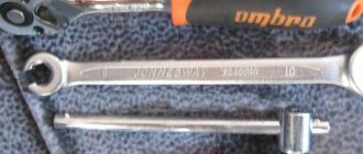
In order to adjust the door you will need a 15 mm socket with a ratchet. So, let's look at how the process happens:
- Unscrew the bolts securing the door hinges.
Checking doors for gaps
Video tutorial from the Renault concern or how doors are adjusted at the factory
Reasons for failure
There are not many reasons for the phenomenon that served as the reason for adjusting the door on the Renault Duster. Let's look at which ones:
- Sagging of door hinges associated with long-term use.
- Repair and restoration work after an accident and body damage. Incorrect body dimensions.
- Hinge breakage due to other actions.
All these reasons are not terrible, but they lead to the fact that the door needs to be opened. One of the signs that adjustment is needed is poor opening and closing of the lock.