A look at the new
Of course, incandescent lamps are still widely used in automotive applications.
Moreover, this applies not only to inexpensive domestically produced cars, but also to middle-class foreign cars with relatively poor configurations. In addition, it can be noted that LED lamps have a much longer service life and practically do not fail. For comparison, the average lifespan of incandescent bulbs on a car is 2-3 years, while LED lighting typically lasts up to 10 years if the car is used continuously.
The brake light must have one more important property: resistance to moisture, temperature changes and other unfavorable climatic factors. An incandescent lamp weakly possesses all of the above properties; in the cold it often breaks down and requires replacement. In addition, the contacts in the base of such a lamp inevitably turn sour and do not allow it to burn at full power.
It is also impossible not to say that the LED brake light significantly saves the current of the generator and battery: comparing the exact data, it is easy to find out that burning a diode requires almost 8 times less energy consumption than in the case of incandescent lamps.
Standard option
Do-it-yourself wood-burning car drawings
The standard brake light works on cars that were produced in the last half century. Before this, no additional light was installed, and only the rear lights worked to improve visibility at night and in fog.
Usually the signal is built into the dimensions. This was not only an excellent solution in terms of ergonomics, but also made it possible to avoid additional costs for the flashlight housing and separate fasteners located on the body.
What does a brake signal consist of and due to what components does it work? Of course, the main and one of the most important components is the flashlight body. If we are talking about installation of dimensions in the case, then this is what is meant here. What is the purpose of such a body? Firstly, it protects the light bulb from mechanical damage, be it shocks, impacts or shaking. Secondly, usually the housing dimensions are absolutely sealed. Obviously, this allows you to achieve maximum protection from moisture and corrosion, which can have a detrimental effect on the wiring.
There is always a light source inside the case, which lights up when the relay is activated and goes out as soon as the relay stops supplying voltage. On older cars, the brake light is represented by a low-power incandescent light bulb, designed to operate on a DC network. Modern cars widely use LED lights, which provide a brighter beam of light and many other benefits.
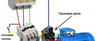
The brake light relay is activated when the driver activates the brake pedal or handbrake with his foot. Typically the relay is connected to a button, which is located under the pedal or lever. As soon as the relay is activated, an electrical impulse is sent from the generator or battery, due to which the light comes on, and the driver behind remains warned that the car is about to slow down.
Switch - brake light
| Road illumination with symmetrical (a and asymmetrical (b) low beam headlights. |
DIY car camouflage
Brake light switches are hydraulically or pneumatically actuated.
The brake light switch is mechanical and actuated by the brake pedal. When you press the brake pedal, the switch rod is released and, under the action of the spring, moves together with the contact plate, which closes the electrical circuit of the brake light lamps through the contacts.
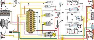
Brake light switch 14 is installed on the brake valve (see Fig. 151) or on the main brake cylinder.
If the brake light switch is too close to the pedal, it will not return to its original position. Valve 18 (see Fig. 105), pressing against body 21, separates cavities A and B, and the wheels are incompletely released when the pedal is released.
Switching equipment includes: brake light switches, central and foot light switches and other switches for various consumers.
The free travel of the pedal in VAZ cars is regulated by moving the brake light switch together with the buffer with the lock nut unscrewed. When adjusting, the gap between the hemispherical end of the pusher and its supporting surface in the master cylinder piston should be no more than 1 mm, which corresponds to a pedal pad travel of about 4–5 mm.
The rear light of VAZ-2105, VAZ-2108 cars includes: a side light and fog light lamp with a red lens, a mechanical brake light switch, actuated by the brake pedal. When you press the brake pedal, the switch rod is released and, under the action of the spring, moves together with the contact plate, which closes the electrical circuit of the brake light lamps through the contacts.
For example, at the Italian Lancia plant, an enlarged set consisting of a steering column, a gear lever and mechanism, a clutch pedal, a brake pedal, a hydraulic brake master cylinder and a brake light switch is mounted entirely into the car body. Previously, these assembly groups were each installed into the body independently. Also pre-assembled enlarged sets of the rear axle, front subframe with engine, axle and suspension and other sets.
The brake light warns that a car or tractor is braking. The brake light switch can be mechanically, hydraulically or pneumatically actuated and operates regardless of the position of the central switch.
The central light switch must be checked by moving the rod with the handle alternately to all three positions. When checking the operation of the brake light switch, it is necessary to have someone behind you to confirm that it is turned on.
| Holes in the brake.| General view of the wheel. |
The full travel of the brake pedal should be approximately 140 mm. The pedal stroke is adjusted by moving the brake light switch 6 (Fig. 318), the rod of which has a rubber tip attached to it.
To avoid this mode of operation, blocking is used. When the brake pedal is pressed, the brake light switch 3 comes into action, which closes its closing contacts, supplying voltage to the coil of the auxiliary relay BP. The relay operates and opens its normally open contact.
| Marking screens for headlight adjustment. |
Replacing the brake light bulb
Basically, replacing a lamp may be necessary if it is burnt out, but this article will tell you what to do if you replace the lamp and it still does not light.
So, we made sure that the light bulb burned out after all.
Replacing the bulb in the main brake light is no more difficult than replacing the low beam bulb. In this case, you need to disconnect the battery and begin replacement work. To do this you need to perform the following manipulations:
- Open the trunk.
- Unfold the trunk lining.
- Disconnect the wiring harness from the rear markers (if your front marker lamp has burned out, then read the material: replacing the front marker light on a Renault Logan).
Disconnect the power harness - We unscrew the two screws, for this you will need a screwdriver with an asterisk (two plastic nuts, if it is a Logan 2 phase).
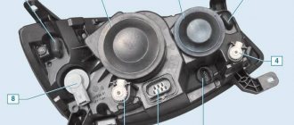
Two lambs are marked with arrows - Pull the headlight towards you and remove it.
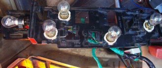
Removing the rear parking light unit - The panel with light bulbs is attached to 3 latches, remove it and change the burnt out lamp.
We put everything back together; on the other headlight the work is done in the same way. Replacing the license plate light bulb is almost the same.
When replacing, do not touch the lamp bulb; any grease that gets on it will speed up its failure.
Replacing a brake light bulb on a Renault Logan in a new body
The replacement is similar, only the rear marker light mountings have changed slightly. The rear dimensions are secured with one wing, which must be unscrewed. After this, pull the headlight towards you.
>
Unscrew the lamb (photo of the editorial car)
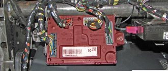
Rear marker block on the right (editorial car photo)
Rear lights close up (editorial car photo)
Replacing the additional brake light lamp
Everything is done as simply as possible. Replacement is made from the trunk.
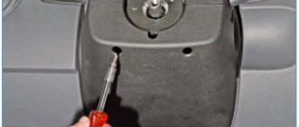
- To replace, turn the lampshade to the left (counterclockwise) and remove it from its seat.
Turn counterclockwise, as in the photoRemoving the shade and lamp
- Next, disconnect the light bulb and replace it with a new one.
Removing the lamp from the socket - The lampshade is installed in place.
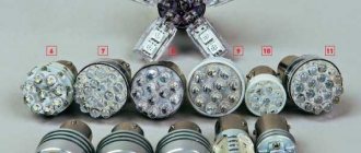
Lamp selection
- For an additional brake light, the manufacturer recommends using halogen lamps marked P21W. The power of this standard light bulb is 21 W, voltage 12 V.
- For brake lights on Renault Logan, single-strand options are used.
It is important to select the correct replacement lamps. Osram Original Line 12V is considered one of the best
They have a long service life. In this case, there is no decrease in luminosity, and the bulb does not dim.
Another option for halogen lamps is Philips VisionPlus P21W. They are usually sold in packs of 2. They can be used not only for additional brake lights, but also for markers.
What is the use of a flashing brake light?
DIY car window lift repair
A Formula 1 brake light, when activated, attracts more attention than a light that is constantly on. And all because blinking is a strong irritant for the human eye compared to a static, unchanging glow. This makes the flashing brake light more visible to other participants. And since this increases safety, then why not install such equipment on your car, especially since there is nothing complicated in the design of such a device, and it is quite possible to make a flashing brake light with your own hands. But this can only be done by a car enthusiast with at least a little knowledge of radio electronics.
To make a blinking brake light with your own hands, a microcircuit is included in the power supply circuit for the rear equipment, which will provide the flickering. The simplest design means that when you press the brake pedal, the light will flash with the same intensity. But there are also more “advanced” blinking brake light circuits in which you can set the operating algorithm.
Types of schemes
Let's look at how to make a flashing brake light based on the K561LA7 microcircuit. This microcircuit is built on 4 logical elements with the designation 2I-NOT. Two of them are dedicated to the multivibrator, and the third is an inverter, whose task is to separate the multivibrator from the analog circuit, which ensures a clearer signal. As a result, we obtain the required output pulses.
brake light diagram for car
Next, the pulse is sent to the base by the KT816B transistor, which provides supply/locking of electric current.
Also, some additional elements may be included in the circuit - a capacitor and a diode.
The capacitor present in the circuit sets the operating frequency of the multivibrator. Its small capacity will ensure a high flickering frequency; as the capacity increases, the blinking frequency will decrease. Additionally, the flicker frequency is affected by the resistor present in the circuit, which charges the capacitor. A diode in the circuit is needed to prevent the capacitor from completely discharging.