01/04/2020 3,787 Electrical wiring and electrical circuits
Author:Ivan
The electrical wiring of all versions of the VAZ 2107 is the same, with the exception of the engine compartment wires. The electrical network is built according to a single-wire circuit, the second conductor is the car body and the crankcases of the units. When using VAZ 2107 electrical circuits, you should take into account the likelihood of a restoration repair being carried out on a particular vehicle, since sections of the wiring may have been replaced.
[Hide]
Failure of the main vehicle systems
The reason for the sudden failure of many components of the VAZ 2107 car may be damage and failure of electrical wiring elements.
The most common wiring failures are listed below:
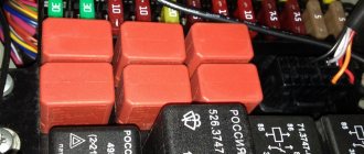
- A common defect is a blown fuse link caused by a circuit overload or short circuit. Since the electrical circuit of the VAZ 2107 often uses old-style fuses, oxidation or loosening of the contact clamps in the mounting block often occurs. To correct these faults, replace the fuse or clean the contacts. The latest car releases used mounting blocks with blade fuses, which provide better contact and more reliable operation of the electrical circuit.
- A more complex case is the burning or oxidation of conductive tracks in the mounting block. To repair, the unit is removed from the car, the damaged areas are soldered and covered with protective varnish. In case of critical damage, the unit must be replaced.
- When a section of the wiring is short-circuited, the fuse-link will constantly burn out. To find a damaged element, you need to test the circuit with a multimeter. Replaced wires should be carefully laid along the standard route. An open circuit is also determined by the continuity of the wires.
- If there is a problem with the components of the injection system, the Check Engine indicator light on the instrument cluster may turn on. The cause may be sensor failure or broken circuits. To find the causes of damage, you should diagnose the injection system using a test device connected to the diagnostic connector. The error codes available in the system can be deciphered and repairs are made based on this data.
- The cause of complete inoperability of the electrical system may be a discharged battery or oxidation of the negative wire that is connected to the body. A low battery is indicated by a dim glow of the control lamps and their complete shutdown when a load is connected (horn or an attempt to crank the engine with the starter).
- A burning battery charging lamp with the engine running indicates a malfunction of the generator or an open circuit connecting the generator to the battery.
- Light pulsations when the engine is running are a symptom of a burnt-out control relay on the generator. The relay must be replaced, since operating the vehicle with increased voltage in the on-board network is unacceptable.
The video provided by the Avtoelektrika HF channel shows the repair of the wiring of the reversing lights on a VAZ 2107.
Where is the wiper relay located on the VAZ 2107?
VAZ 2107 is one of the most common cars in Ukraine. It is famous for its ease of repair and reliability. All this car needs is the care of the owner, good oil in the engine and gearbox and it will serve faithfully. One of its few problems is the wiper relay that often fails. This leads to the fact that the windshield wipers do not work at all, or their cycling gradually slows down. To restore the functionality of the device, the relay must be replaced, but this is not so easy. This article describes the location of the wiper relay on a VAZ 2107 and the process of replacing it with a new one.
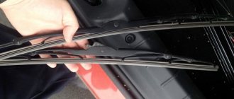
How do wipers work and why are they needed?
The main task of windshield wipers is to create a good level of visibility in bad weather and to clear water and dirt from the car's windshield. Special auto chemicals and the use of the right washer can help them with this. Windshield wipers operate thanks to a special gear motor, powered by the vehicle's on-board circuit. And the relay marked RS-514 is responsible for the frequency of operation. The VAZ 2107 has two wiper operating modes - constant and cyclic, with a pause of four seconds. The efficiency of wipers is directly related to the quality of the battery; you can buy a good battery from us.
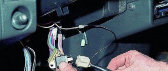
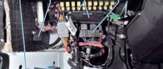
The windshield wiper relay, as one of the most important elements of the system, is located under the dashboard, on the left. It is fastened with two screws hidden under the upholstery. The connection is made using a special plug located near the headlight hydraulic adjustment handle. To check the device, the plug must be disconnected and pulled out.
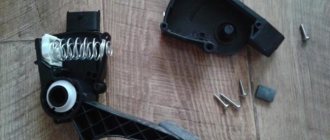
Basic device
Knowing where the windshield wiper relay is located on the VAZ 2107 in the injection and carburetor versions is not enough. To carry out repairs, you should study the principle of operation. This device looks like a black box, inside of which there is a microcircuit and electronic components responsible for the proper operation of the wipers. The microcircuit consists of the following elements:
- electromagnetic coil;
- resistor and capacitor;
- microcontroller HP37.
The connection is made using four wires, through which the wiper motor is controlled.
How to replace the wiper relay
To begin with, it should be noted that in the carburetor and injection versions of the car the relay is absolutely identical. Next, you need to check the functionality of this device. The easiest way is to take a known working device from another machine and connect it. If the windshield wipers work, then the problem is here. In theory, if you have certain knowledge, you can try to restore it by identifying the failed element and replacing it. But if you need to fix your car urgently, the easiest way is to replace the device with a new one. This is very easy to do:
- Remove the negative terminal from the battery, de-energizing the entire on-board network of the vehicle.
- Unscrew 2 screws.
- Take out the plug, put it on the new device and screw it into place.
How does the wiper relay work?
The operation of the windshield wiper involves a chain of elements, which includes an electric motor, a fuse, a power button and a relay. The latter performs the most important function, managing the entire process. It functions as follows:
- When you press the power button, power is supplied to the relay, the contacts inside close, the coil turns on and the wiper gear motor starts working.
- Over the next 3 seconds, the bimetallic plate inside the device heats up, and the power from the electric motor of the VAZ 2107 windshield wipers is lost.
- After this, the panel cools down quickly enough and the wipers start working again.
- If the delayed operation mode is turned on, the main resistor distributes the electromotive force so that the delay necessary for the cyclic operation of the wiper is formed.
As you can see, the scheme is quite simple, and almost all repairs come down to replacing failed components with new ones, so you can do everything yourself.
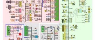
Electrical diagram of VAZ 2107 with carburetor
Since the production of the VAZ 2107 lasted from 1982 to 2013, many changes were introduced in the electrical circuit (including the appearance of new components), which entailed adjustments in the thickness and color of the wire insulation and their routing along the body. Below are electrical diagrams of a VAZ 2107 with various ignition systems.
Contact ignition system
Electrical diagram of a VAZ 2107 with classic ignition
Designation of components with descriptions shown on the electrical diagram:
- Headlight.
- Direction indicators located on the side of the front fenders.
- Battery 12 volt.
- Starter activation contact group.
- Electric valve on the carburetor.
- Limit switch.
- Generator model 372.3701. When installing generator 9412.3701, the connection diagram is identical.
- Drive for headlight cleaners (optional).
- Thermal sensor for turning on the fan drive.
- Electric fan drive.
- Klaxon.
- Contact distributor of ignition pulses.
- Candle.
- Starter.
- Liquid temperature measuring sensor.
- Underhood lighting.
- Emergency pressure indicator.
- Emergency brake fluid level indicator.
- Electric motor and drive gear for windshield wipers.
- Valve controller on the carburetor.
- High voltage coil.
- Headlight washer pump drive (optional, comes with item 8).
- Window washer pump drive.
- Switching block with relays and fuse links.
- Contact group of the electric windshield wiper drive.
- Contact group ensuring the operation of turn signals and hazard warning lights.
- End activator of brake lamps.
- Reverse gear indicator limit activator.
- Contact group ensuring the operation of the ignition system.
- Ignition on and off system.
- Steering column unit with three levers for switching operating modes of headlights, turn signals and windshield wipers.
- Button for activating the alarm system.
- Socket for connecting the connector of a portable lamp.
- Three-position heating fan intensity switch.
- A control resistance that provides a change in the rotation speed of the heater fan.
- Control indicator for the electric glass heating system.
- Brake fluid level drop indicator.
- Housing for installation of control indicators.
- Electric fan drive for the heater air system.
- Illuminated glove box on the instrument panel.
- Interior lighting switches installed on the B-pillars.
- Limit switches for open door warning lamps (found on cars produced before 1998). Since 1998, these switches are used only to turn on the two interior lamps mounted on the B-pillars.
- Door open lamps (used in conjunction with position 42).
- Connection connector.
- Cigarette lighter.
- Quartz clock mounted on the center console.
- Switch for operating mode of instrument lighting.
- A control diode designed to check the brake fluid level indicator.
- A device showing the amount of fuel in the tank.
- Gasoline reserve indicator indicator.
- Speedometer with mechanical drive.
- Indication of a working turn signal.
- Choke indicator (air damper used to enrich the mixture when starting a cold engine).
- Battery charging indicator.
- Choke limit switch installed under the damper drive handle.
- Instrument cluster assembly.
- An econometer showing the degree of vacuum in the intake manifold.
- Limit switches for interior lighting mounted on the rear pillar.
- Engine fluid temperature indicator.
- Speed indicator.
- Handbrake control indicator.
- Oil pressure drop indicator.
- High beam connected circuit indicator.
- Indicator that side lights and low beam are on.
- Voltage indicator in the on-board network.
- Limit switch under the handbrake lever, used to turn on the indicator on the instrument cluster.
- Switch for operating modes of dimensions.
- Key for selecting the rear window heating operating mode. The key contains an indicator lamp that lights up when the heating is turned on.
- Rear optional fog light switch. The key has an operation indicator.
- Additional fog light circuit fuse (comes with item 69). The fuse is located under the headlight mode switch.
- A single dome light, installed only on vehicles with a solidly molded ceiling panel. This ceiling is found on cars manufactured before the mid-90s. With the beginning of the use of a soft ceiling, the interior lights moved to the central pillars (position 41).
- Combined headlights on the rear of the car.
- A sensor installed in the tank that serves to determine the gasoline level.
- Wire connectors used to connect the rear window heating system.
- License plate lamps.
The connector blocks are shown separately, indicating the contact numbers:
- position A - connectors for headlights, glass cleaning system and carburetor valve controller;
- position B - connecting block on the fuse block and steering column unit;
- position B - connecting the contacts of the turn signal control relay;
- position G - rear lights;
- position D - alarm mode switch.
On VAZ 2107 cars of the first years of production, the G-222 generator was used, which was later replaced by the more powerful and modern model 372.3701.
Early version with generator G-222
Late version with generator 372.3701
The table details the elements of electrical circuits of generators.
| Position | Scheme G-222 | Scheme 372.3701 |
| 1 | Generator | Battery |
| 2 | Diode on negative wire | Diode on negative wire |
| 3 | Diode on positive contact | Additional diode |
| 4 | Field winding | Generator |
| 5 | Voltage level regulator | Diode on positive contact |
| 6 | Rotor winding | Field winding |
| 7 | Radio interference suppression system | Voltage level regulator |
| 8 | Battery | Rotor winding |
| 9 | Charging warning light relay | Radio interference suppression system |
| 10 | Relay block | Relay and fuse box |
| 11 | Charging indicator on the instrument cluster | Charging indicator on the instrument cluster |
| 12 | Voltage meter | Voltage meter |
| 13 | Ignition control relay | Ignition control relay |
| 14 | Ignition switch | Ignition switch |
Contactless system
Since 1987, machines with a non-contact principle of spark generation began to be produced. The electrical circuit of the machines has undergone changes only in relation to the components of the ignition system. Below is a detailed diagram of the ignition system.
Components of a non-contact ignition system
- 1 - candle;
- 2 — pulse distributor;
- 3 — protective screen;
- 4 — a non-contact sensor installed inside the distributor, similar to the VAZ 2104/2105;
- 5 - electronic switch;
- 6 - coil;
- 7 — mounting block;
- 8 - distribution relay;
- 9 — operating mode switch.
The symbol A+ in the diagram indicates the generator output. Optionally, an additional relay installed in parallel with the main one can be used in the circuit.
Wiper relay functions
Windshield wipers operate thanks to an electric motor that supplies 12V voltage.
But this is a very large power, implying a significant amount of constant current. Specifically, to reduce the constant current in the electrical circuit, a relay of the RS-514 format is installed, which regulates the frequency of movement of the wipers. The VAZ-2107 car is equipped with 2 variations of windshield wiper movement - one is possible without a break, the other has a pause of 4 seconds. The windshield wiper relay on the windshield in the VAZ-2107, namely where it is located, is of interest to many car owners; otherwise, repairing the windshield wipers in some cases becomes impossible. So, the mechanism is located under the dashboard on the left with the orientation towards the driver’s seat. The fasteners are made directly to the body of the VAZ-2107; 2 screws located under the upholstery act as reliable fasteners. When examining the relay, you can see that there is a wiring coming to it, at the end of which there is a plug for connecting the device.
The connector, which is responsible for connecting the plug, is located on the panel with devices near the headlight hydrocorrector control. To carry out repair work, you need to get it from below. If you doubt that you have selected the correct plug, unplug it and check that the windshield wipers are working.
If the lever is in position 1, but the wiper does not work, the mechanism is not turned on.
Replacing the VAZ classic wiper relay
We fix glitches of wipers on the Classic.
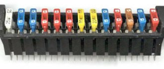
New model fuse and relay block (mounting block) VAZ 2104, 2105, 2107 AVAR (402 and 404)
Review of new model mounting blocks for the classic VAZ 2104, 2105, 2107 manufactured by AVAR 402.3722 ...
Wiring diagram VAZ 2107 with injector
Depending on the year of manufacture of the car, it may use an ECM (electronic engine control system) of the General Motors and January brands. Cars with different ECMs have different wiring and arrangement of electrical circuit elements in the engine compartment.
Electrical diagram of VAZ 2107 with GM system
- 1 — fan drive for air supply through the radiator of the cooling system;
- 2 - switching block;
- 3 — idle system;
- 4 — General Motors controller;
- 5 — exhaust gas toxicity regulator (octane potentiometer).
- 6 - candles;
- 7 — ignition system module;
- 8- sensor that determines the position of the pulley on the crankshaft;
- 9 — fuel pump with a level meter integrated into the circuit;
- 10 — revolution counter;
- 11 — ECM system status indicator (Check Engine);
- 12 — ignition system activation relay;
- 13 — electronic speed sensor;
- 14 — diagnostic block;
- 15 — fuel injection device;
- 16 — valve for the fuel vapor recovery system;
- 17 — safety element 15 A of the fuel pump;
- 18 — safety element 15 A of the ignition system;
- 19 — safety element 15 A of the ECM;
- 20 — ignition system control relay;
- 21 - contact group for controlling the operation of the pump;
- 22- control element of the electric heating system of the intake manifold;
- 23 - electric heating element installed in the intake manifold;
- 24 - 15 A fuse-link to protect the intake pipe heating circuit;
- 25 — lambda probe;
- 26 — engine temperature meter;
- 27 — throttle controller;
- 28 — intake air temperature meter;
- 29 — absolute atmospheric air pressure meter at the engine inlet;
Electrical diagram of VAZ 2107 with system January 5.1.3
- 1 - candle;
- 2 — injection nozzle;
- 3 - control module for the ignition system;
- 4 — diagnostic block;
- 5 — electric fuel pump with a built-in fuel level sensor;
- 6 — electronic speed signal meter;
- 7 — connecting harness for connecting to the wiring in the instrument panel;
- 8 — sensor for measuring the amount of air consumed;
- 9 — throttle valve control drive with a built-in opening angle measuring system;
- 10 — engine temperature meter;
- 11 — system for regulating idle speed parameters;
- 12 — January control unit;
- 13 - supplying a positive 12 V signal from the electrical circuit;
- 14 — lambda probe;
- 15 - sensor measuring the position of the crankshaft;
- 16 — electromagnet for controlling the purge valve of the gasoline vapor recovery system;
- 17 — connection of the ECM system to the mounting block;
- 18 — positive power output connector to the electric motor of the cooling system;
The circuit additionally contains a block with relays and blade circuit fuses to protect the components of the ECM system (15 ampere rating):
- main control relay R1;
- fan starting system R2;
- fuel supply pump starting system R3;
- main relay fuse F1;
- block circuit fuse January F2;
- pump power supply fuse F3.
The unit is located in the dashboard in a niche under the glove box.
The latest releases of the VAZ 2107 were equipped with an ECM system based on the January 7.2 controller.
Electrical diagram of a VAZ 2107 with the January 7.2 system
The diagram shows:
- 1 — block January 7.2;
- 2 — cooling fan with electric drive;
- 3 — plug connecting the wiring harness of the ignition system with the main wiring of the car on the left mudguard;
- 4 - similar connection on the right mudguard;
- 5 — indicator of the amount of fuel in the tank;
- 6 — wiring connection to the indicator;
- 7 — lambda probe;
- 8 — plug connecting the fuel level indicator to the ignition system wiring;
- 9 — fuel supply pump;
- 10 — speed level meter;
- 11 — idle system with automatic regulator;
- 12 — throttle position controller;
- 13 — liquid temperature meter;
- 14 - sensor that measures the mass of air supplied to the cylinders;
- 15 — diagnostic connector;
- 16 — position sensor of the main engine shaft;
- 17 — system for purging the tank of the fuel vapor recovery system;
- 18 - module;
- 19 — candles;
- 20 — fuel injection devices;
- 21 — connecting blocks between the ECM system harnesses and the instrument panel;
- 22 — fan controller;
- 23 - fusible element of the January controller circuits (15 A);
- 24 — ignition controller;
- 25 — ignition control circuit fuse (knife type 15 A);
- 26 - protective fusible element of the fuel pump electric motor circuit (15 A);
- 27 — fuel pump controller;
- 28 — connecting block of the ECM system and injector wires;
- 29 — mating part of the injector harness block;
- 30 — connection of ECM wires and instrument panel;
- 31 — ignition switch;
- 32 — instrument cluster;
- 33 - Check Engine lamp installed on the combination.
The diagram additionally indicates:
- output point to the positive terminal of the battery (letter A);
- grounding the wiring of the fuel level meter (point B1);
- grounding of the ignition system (points B2 and B3).
The rest of the electrical circuit remains unchanged and corresponds to the circuit drawings of later carburetor cars. The connection of the new injection wiring with the remaining components is made in the mounting block.