Design of the headlamp on the VAZ-2114
General view of the headlight
Almost all motorists use car headlights, but not everyone knows about the features of its design, as well as its structure. Thus, it is worth considering this issue in more detail.
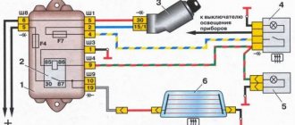
Diagram of elements of the headlight unit of the VAZ-2114 car:
Diagram of the device and connection of the headlamp
- Reflector:
- Reflector bottom support.
- Wiper brush limiter;
- Lower reflector holder:
- Headlight diffuser.
- lamp flange:
- High beam thread;
- Low beam filament screen;
- Low beam thread;
- Turn signal lens;
- Lamp AI2-21-3;
- Stub. installed instead of the hydraulic corrector working cylinder;
- Upper reflector holder;
- Tension spring:
- Lever arm:
- Lever return spring;
- Screw for vertical headlight adjustment:
- Case:
- Sleeve;
- Working cylinder rod:
- Cuff;
- Working cylinder body:
- Headlight housing;
- Lamp AKG12-60+55;
- Screen;
- Lamp A12-4:
- Screw for horizontal headlight adjustment:
- Headlight mounting stud;
- Headlight housing;
- Hydraulic corrector main cylinder housing;
- Tubes connecting the master cylinder to the workers:
- Double piston:
- Drive screw;
- Lever;
- Nozzle:
- Lid:
- Block headlight;
- Mounting block;
- Relay for low beam headlights;
- Ignition switch;
- External lighting switch;
- Headlight high beam warning lamp;
- Headlight switch;
- Headlight high beam relay;
- I. Scheme of operation of the headlight hydraulic corrector:
- A-car with one driver:
- B-with the driver and cargo in the trunk;
- I. Headlight switching diagram;
- III. View of the headlight plug connector: a low beam plug; V. high beam connector: c side light connector: d ground connector
Practical recommendation for replacement
The headlight unit on a VAZ-2114 is quite simple and easy to change, but the process itself requires some practical and theoretical skills. Therefore, consider the sequential replacement process:
- Disconnect the negative terminal of the battery.
- We dismantle the radiator protective lining.
Removing the plastic protection of the top panel of the radiator
Unscrew the holding screw. It is better to remove the headlight assembly with turn signal
Unscrew the side mount of the headlight unit
We dismantle the headlight
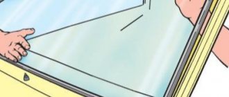
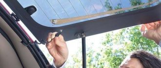
How to check heating?
To do this, you need to wrap the voltmeter probe in aluminum foil and press the foil with your finger and move it along the conductive threads. This way you can detect where the threads are broken.
Initially the voltmeter will show a voltage of 6V. If it displays 12 V, then in this place there is a break in the thread on the side between the connection point of the voltmeter and the heater side. If the voltage is below 0 V, then the conductive strip has a break on the side between the connection point of the volt meter and the heater side.
use an ohmmeter to measure the resistance of the conductive strip between the side terminal of the heater and the center of the strip. The section of the strip with the gap will have twice the resistance of the remaining strips.
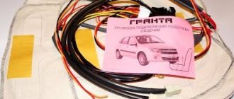
You can repair a conductive strip using a conductive mass: glue mixed with metal shavings, a special material. You will also need electrical tape, solvent, and a brush. Use a solvent to clean the area of the glass where the conductive strip of the heater breaks. Electrical tape will be needed as a stencil. Apply conductive compound and remove adhesive tape. After a day, you can remove the excess.
Most electrical circuits are protected by fuses. Electric motors of gear motors (windshield wipers, rear window wipers (VAZ-2108, -2109), headlights - if installed) are protected by automatic reusable bimetallic fuses. The power supply circuit of the injection system (engine 2111) is protected by a fuse-link made of wire with a conductor of reduced cross-section (1 mm2). The battery charging, ignition (carburetor engines), engine starting, and the “generator - ignition switch - mounting block” circuits are not protected. Powerful consumers (starter, headlights, cooling system fan motor, electric fuel pump, etc.) are connected via a relay.
conclusions
Installing and replacing a VAZ-2114 headlight is a fairly simple and understandable process that every motorist can do with his own hands. So, if a car enthusiast is not able to carry out the process himself, he must contact a car service center, where they will always help.
I love articles like this, especially those that give a detailed analysis that you can do yourself on the weekend))
I'll have something to do this weekend)) I think I'll replace the headlights with new ones in a couple of hours. Quite a lot of nuances, especially for a beginner. Thanks for the instructions.
Schematic electrical diagrams, connecting devices and pinouts of connectors
Detailed color diagrams of the VAZ 2114 wiring (carburetor, injector) are provided with a description of the electrical equipment for various modifications. The information is intended for self-repair of cars. Many electrical circuits are divided into several sections for ease of viewing via a computer or smartphone; there are also circuits in the form of one picture with a description of the elements - for printing on a printer.
The VAZ 2114 (Samara-2) car is built on the VAZ 21093 platform and is an improved version of it. The first prototype of the hatchback was assembled back in 2000. A year later, the Volzhsky Automobile Plant produced the first pilot batch of 50 VAZ-2114 cars, and in the same 2001 the hatchback was first introduced to the market. The interior features a new instrument panel, a new steering wheel, an adjustable steering column, power windows and a new heater. Years of production 2114: 2001—2013
The fourteenth model was previously equipped with a 1.5 liter eight-valve engine, borrowed from the VAZ 2111 model with an injector. A little later it was replaced by the VAZ 11183-1000 version, which complies with the Euro-3 standard. The VAZ 2114 injector received a more powerful engine, and this is one of the reasons that the wiring of the 2114 has also changed.
A wiring harness has been added for connecting to the electronic switch. A harness has also appeared for connecting to the ignition module terminal.
Replacing high-voltage wires will require additional attention, because the connection procedure depends on the year of manufacture of the car. Until 2004, 4-pin ignition modules were installed, and after that - 3-pin. Connecting the adsorber valve to the injection system controller also provided another additional element. An adsorber is an electromechanical device used for ventilation and removal of condensate in a gas tank. Complications also affected the interior part. The dashboard received improvements in the form of the appearance of a BC (on-board computer), a new instrument panel and a change in the position of the glove compartment.
Car modifications 2114
VAZ-21140 . Modification with an 8-valve injection engine VAZ-2111, 1.5 liters and 77 horsepower. Serial production from 2003 to 2007
VAZ-21144 . Modification with an 8-valve VAZ-21114 engine, 1.6 liters and 81.6 horsepower. Years of serial production: 2007-2013.
VAZ-211440 . Another modification released in 2007, it was equipped with a VAZ-11183 engine with a volume of 1.6 liters and a power of 82 horsepower. The car was discontinued in 2013.
Wiring diagram VAZ-2114 for old models
Electrical diagram of car 2114: 1 - headlight; 2 [Installed on a part of the car] - fog lamp; 3 — ambient air temperature sensor; 4 — electric engine radiator fan; 5 — block for connection to the wiring harness of the engine control system; 6 — engine compartment lamp switch; 7 [Installed on a part of the car] - reserve block for connecting an audio signal with one terminal (the negative terminal is connected to the body); 8 — sound signal; 9 — liquid level sensor in the windshield washer reservoir; 10 [Installed on a part of the car] - brake pad wear sensor; 11 — low oil level sensor; 12 - generator; 13 [Installed on a part of the car] - engine compartment lamp; 14 — temperature indicator sensor; 15 — starter; 16 — battery; 17 [Installed on a part of the car] - relay for turning on fog lights; 18 — coolant level sensor in the expansion tank; 19 — sensor of insufficient brake fluid level; 20 — reversing light switch; 21 — windshield wiper gear motor; 22 — emergency oil pressure sensor; 23 — rear window washer electric pump; 24 — electric pump for windshield washer; 25 — instrument panel; 26 — mounting block of fuses and relays; 27 — brake signal switch; 28 — ignition relay; 29 - ignition switch (lock); 30 — glove box lighting lamp; 31 — switch for the glove compartment lighting lamp; 32 — rear window heating switch; 33 — rear fog light switch; 34 [Installed on a part of the car] - fog light switch; 35 - combined switch for side lights and headlights; 36 — alarm switch; 37 — steering column switches; 38 — brightness control for instrument lighting; 39 — illumination lamp for the headlight hydraulic adjustment control handle; 40 — socket for connecting a portable lamp; 41 — side direction indicator; 42 — interior lighting switch (front door open sensor); 43 — interior lamp; 44 — electric fan of the ventilation and heating system; 45 — additional resistor of the electric fan of the ventilation and heating system; 46 — switch for operating modes of the electric fan of the ventilation and heating system; 47 — illumination lamp for the handle of the operating mode switch of the electric fan of the ventilation and heating system; 48 — backlight lamp for the heater control unit; 49 — display unit of the on-board control system; 50 [Installed on part of the car] - trip computer; 51 — interior lighting switch (rear door open sensor); 52 [Installed on a part of the car] - block for connecting a clock; 53 — fuel module; 54 — ashtray illumination lamp; 55 — cigarette lighter; 56 — interior lamp; 57 — switch for the parking brake warning lamp; 58 — rear light; 59 — license plate light; 60 — additional brake light; 61 — heating element for heating the rear window; 62 — rear window wiper gear motor; A - numbers of pins in connecting blocks.
Rear window heating mechanism
Using relay type 113.3747, the rear window heating element is switched on. In this case, indicator lamp 5, which is located next to the switch, lights up. She illuminates the switch key with orange light. Only when the ignition is on can you turn on the heated rear window, because voltage is supplied to the switch through an additional relay, which is activated when the ignition is turned on.
Through the relay contacts, power is supplied to the heating element from a fuse directly connected to the power source. If when the heating of the rear window of the VAZ 2109 is turned on and the glass is not heated, then you should check the fuse, wires and connections, switch, relay.
If the heating element fails, it is advisable to replace the glass, however, it is much more convenient to purchase a kit for restoring damaged threads.
The heated rear window of the VAZ 2109 defrosts the rear window. Consists of parallel conductors sprayed onto glass. An electric current is passed through them, the conductors heat up and defrost the rear window, also clearing it of moisture. The relay located in the engine compartment fuse box supplies current. If after fifteen minutes the glass is still not cleared, then you need to turn on the heater for the second cycle.
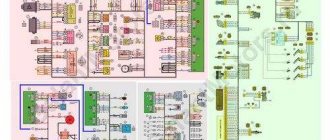
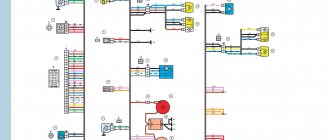
VAZ-2114 diagram (second option)
Electrical diagram of VAZ-2114 cars (without engine control system):
1 — block headlights; 2 — fog lights; 3 — air temperature sensor; 4 — electric motor of the engine cooling system fan; 5 — blocks connected to the wiring harness of the ignition system; 6 — engine compartment lamp switch; 7 — block for connecting to a single-wire type audio signal; 8 — sound signal; 9 — washer fluid level sensor; 10 — front brake pad wear sensor; 11 — oil level sensor; 12 - generator; 13 — engine compartment lamp; 14 — coolant temperature indicator sensor; 15 — starter; 16 - battery; 17 — relay for turning on fog lights; 18 — coolant level sensor; 19 — brake fluid level sensor; 20 — reverse light switch; 21 — windshield wiper gearmotor; 22 — oil pressure warning lamp sensor; 23 — block for connecting to the rear window washer electric motor; 24 — electric motor for windshield washer; 25 — instrument cluster; 26 — mounting block 2114; 27 — brake light switch; 28 — ignition relay; 29 — ignition switch; 30 — glove box lighting lamp; 31 — glove box lighting switch; 32 — rear window heating element switch; 33 — rear fog light switch; 34 — fog lamp switch; 35 — switch for external lighting lamps; 36 — alarm switch; 37 — steering column switches; 38 — switch for instrument lighting lamps; 39 — lamp for illuminating the headlight hydrocorrector scale; 40 — plug socket for a portable lamp; 41 — side direction indicators; 42 — lamp switch on the front door pillars; 43 — lamp for individual interior lighting; 44 — heater fan electric motor; 45 — additional resistor of the heater electric motor; 46 — heater fan switch; 47 — heater switch illumination lamp; 48 — lamp for illuminating the heater levers; 49 — on-board control system unit; 50 — trip computer; 51 — lamp switch on the rear door pillars; 52 — block for connecting the wiring harness of the engine control system; 53 — electric fuel pump and gasoline quantity sensor; 54 — front ashtray illumination lamp; 55 — cigarette lighter 2114; 56 — trunk lighting lamp; 57 — trunk light switch; 58 — interior lamp; 59 — parking brake warning lamp switch; 60 — rear external lights; 61 — rear internal lights; 62 — block for connection to the rear window heating element; 63 — license plate lights; 64 - additional brake signal located in the spoiler.
Cooling system design features
Depending on the design features, the fan can be turned on in 3 ways:
- using a power sensor for activation of the VSO. This sensor is also called a fan temperature relay, since the power contacts of the electric motor pass directly through the sensor. With this scheme, the load on the thermal relay increases significantly, which reduces its service life;
- using the fan switch sensor, but now closing the contacts in the temperature switch triggers the relay, through which the power contacts of the cooling fan are connected. This connection method is much more reliable than the previous option;
- using an electronic engine control unit. The ECU, focusing on the coolant temperature sensor installed in the engine cooling radiator, supplies power to the VCO through a relay. A resistive temperature sensor is used as a meter. It is this switching circuit that is used on the vast majority of modern cars. On cars equipped with air conditioning, one of the electric fans will be controlled by the comfort unit. This is necessary for forced cooling of the condenser when the interior air conditioning system is activated.
Operating modes
When understanding the operating principle and connection diagram of a radiator fan, you should remember that electric motors often have two speed modes. This is implemented in 2 ways:
- by adding a resistor to the circuit, which increases the resistance and, as a result, reduces the current. The design uses a two-contact sensor, which, depending on the temperature, powers the electric motor directly or through resistors;
- a combination of parallel and series connection. The circuit is used on a car with two fans. They can be connected in series, in which case, according to Ohm's law, they will operate from 6 V, or in series, when 12 V is supplied to each of the VSOs. The modes correspond to low and high speed rotation of the propeller.
Wiring diagram VAZ-2114 new models
The updated engine has a new injection scheme, so it was necessary to use some new devices, as well as replace the ignition coil with a more efficient one and adapted to Euro 3 conditions. In order to comply with them, the engine had to minimize the amount of CO at start-up. And for this it was necessary to lean the mixture. Since a lean mixture ignites worse, it needed a more powerful spark to spark. This explains the use of a coil of increased power.
- block headlights;
- gearmotors for headlight cleaners*;
- fog lights*;
- ambient temperature sensor;
- sound signals;
- engine compartment light switch;
- engine cooling fan electric motor;
- generator VAZ-2114;
- low oil level indicator sensor;
- washer fluid level sensor;
- front brake pad wear sensor;
- wire ends connected to the common windshield washer pump**;
- windshield washer pump;
- headlight washer pump*;
- wire ends for connecting to the rear window washer pump on VAZ-2113 and VAZ-2114 cars;
- low oil pressure indicator sensor;
- engine compartment lamp;
- wire lug for connecting to the engine management system wiring harness;
- windshield wiper gear motor;
- starter VAZ-2114;
- block connected to the wiring harness of the ignition system on carburetor cars;
- coolant temperature indicator sensor;
- reverse light switch;
- low brake fluid level indicator sensor;
- accumulator battery;
- low coolant level indicator sensor;
- relay for turning on fog lights;
- mounting block;
- brake light switch;
- plug socket for a portable lamp;
- hydrocorrector scale illumination lamp;
- parking brake indicator lamp switch;
- block for connecting a backlight lamp;
- switch for instrument lighting lamps;
- Understeering's shifter;
- hazard switch;
- front seat heating element relay;
- ignition switch;
- rear fog lamp circuit fuse;
- front seat heating elements circuit fuse;
- door lock circuit fuse;
- front ashtray illumination lamp;
- ignition relay;
- cigarette lighter VAZ-2114;
- glove box lighting lamp;
- glove compartment light switch;
- heater fan motor;
- additional heater motor resistor;
- heater fan switch;
- heater switch illumination lamp;
- heater lever illumination lamp;
- gear motors for electric windows of the front doors;
- right front door ESP switch (located in the right door);
- gear motors for locking front door locks;
- wires for connecting to the right front speaker;
- gear motors for locking rear doors;
- wires for connecting to the right rear speaker;
- door lock control unit;
- wires for connecting to radio equipment;
- headlight wiper switch*;
- rear window heating element switch;
- rear fog light relay;
- block for connection to the heating element of the right front seat;
- rear fog light switch;
- right front seat heating element switch;
- fog light switch*;
- switch for external lighting lamps;
- left front seat heating element switch;
- block for connection to the heating element of the left front seat;
- wires for connecting to the left front speaker;
- left front door power window switch (located in the left door);
- right front door power window switch (located in the left door);
- wires for connecting to the left rear speaker;
- side direction indicators;
- dome light switches on the front door pillars;
- dome light switches on the rear door pillars;
- lampshade VAZ 2114;
- individual interior lighting lamp;
- block for connecting to the wiring harness of the electric fuel pump;
- trunk light switch;
- instrument cluster;
- trunk light;
- on-board control system display unit;
- trip computer*;
- block for connecting the wiring harness of the engine management system;
- rear exterior lights;
- rear interior lights;
- pads for connecting to the rear window heating element;
- license plate lights;
- additional brake signal located on the spoiler.
Heated rear window of VAZ 2108, VAZ 2109, VAZ 21099
The diagram of the rear window heating system on a VAZ 2108, VAZ 2109, VAZ 21099 is shown in Fig. 9.24.
The rear window heating element is switched on using a relay type 113.3747 installed in the mounting block. When you turn on the heated rear window on a VAZ 2108, VAZ 2109, VAZ 21099 vehicle, indicator lamp 5 lights up (see Fig. 9.24), located next to the switch and illuminating the switch key with orange light. The heated rear window can only be turned on when the ignition is on, since voltage is supplied to switch 4 through an additional relay 2, which is activated when the ignition is turned on.
Power is supplied to the heating element through relay contacts 2 from fuse P4, which is directly connected to the power source.
If the rear window is not heated when the heating is turned on, you need to check fuse P4, wires and their connections, as well as switch and relay 2.
USEFUL ADVICE If the rear window heating element fails, the manufacturer recommends replacing the glass, but now there are special kits on sale for restoring damaged heating element threads, which include all the necessary components, tools and instructions for use.
Rice. 9.24. Diagram of the rear window heating system on a VAZ 2108, VAZ 2109, VAZ 21099:
1 - mounting block; 2 — relay for turning on the heated rear window; 3 — ignition switch; 4 — rear window heating switch; 5 — indicator lamp for turning on the heated rear window; 6 — rear window heating element.
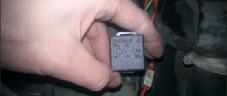
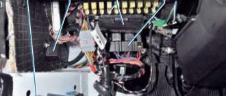
Relays and fuses VAZ 2114
F1 for 10 Amps (A) rear fog lights and rear fog light warning lamp. F2 for 10 A turn signal lamps, turn signal relay, hazard lights, hazard warning lights. F3 7.5 A lamps for interior lighting (both) and trunk, ignition lighting, powertrain control system control lamp, brake lamps, computer, if available. F4 20 A carrier, relay and rear window heating element. F5 20 A horn and its relay, cooling fan. F6 30 A power windows and their relays F7 30 A motor heater, headlight cleaner, windshield washer, cigarette lighter, glove compartment light bulb, rear window heating relay winding. F8 7.5 A right fog lamp. F9 7.5 A left fog lamp. F10 at 7.5 A left side marker, lamp signaling the inclusion of the side light, lamps for illuminating the sign, engine compartment, illumination of switches and instruments, instrument lighting switch. F11 at 7.5 A right side. F12 at 7.5 A right low beam. F13 at 7.5 A left low beam. F14 for 7.5 A left high beam and a light indicating that the high beam headlights are on. F15 at 7.5 A right far. F16 30 A - a light indicating insufficient oil pressure, brake fluid level, engagement of the parking brake, low battery, instrument cluster, relay for monitoring the health of lamps, indication of control systems, reversing lamps, turn indicators and their relays, as well as an alarm if turning mode is turned on, computer, generator excitation winding is turned on at the moment the engine starts.
Heated rear window of VAZ 2109 does not work
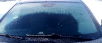
>Heated rear window is a very necessary thing - it protects the rear window from fogging and icing. However, very often it either does not work at all, or only part of the tracks works. I think that many VAZ 2109 owners look at the road through the rear window when reversing. At least that’s how I do it – it’s very convenient. If this glass is foggy or covered in snow, then nothing will be visible. And driving by mirrors, especially when you are used to driving while looking out the rear window, is very inconvenient and scary. And safety when driving a car is important. It’s not very pleasant to drive in reverse, looking at the mirrors and wondering whether you’ll hit someone or not.
Heated rear window of VAZ 2109 does not work
The operating principle of heating the rear window of a VAZ 2109 car is as follows: a conductive mesh is applied to the rear window from inside the passenger compartment. An electric current flowing through this mesh causes it to heat up, and as a result, the rear window of the car also heats up. The heating is turned on by pressing a button on the instrument panel of the VAZ 2109. If the heating of the VAZ 2109 does not work at all, then it is necessary to look for the reason why voltage is not supplied to the rear window mesh. Checking the presence of voltage for heating the rear window of a VAZ 2109 is simple: unplug the two wires connected for heating and measure the voltage between them using a multimeter.
We measure the voltage of the heated rear window of a VAZ 2109
We measure the voltage of the heated rear window of a VAZ 2109
Naturally, before doing this, do not forget to press the heating button on the instrument panel.
Turning on the heated rear window of the VAZ 2109
Turning on the heated rear window of the VAZ 2109
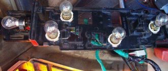
If there is no voltage, then you need to check the heating switch relay in the mounting block, the heating switch button, the condition of the tracks in the mounting block, the integrity of the fuse, and the integrity of the wires to the rear window. If the heating voltage comes on, but the glass still freezes, it means that only part of the tracks are working, or maybe none of them are working at all. To find out which tracks work and which don't, you need to turn on the heating when the rear window fogs up a little. Around tracks that are running, evaporation will disappear. We remember these tracks, or mark them somewhere so as not to forget. The remaining tracks around which the vapors did not dry out are faulty. There is only one problem with more expensive heated rear windows - they are torn. The track can tear spontaneously over time, and the track can also be scratched if something sharp or hard is rubbed on the rear window from the passenger compartment. A broken track can be detected by carefully inspecting each rear window heating track individually.
Broken heating threads VAZ 2109
Heating repair will consist of restoring damaged areas of the paths. That is, it is necessary to eliminate the electrical circuit break and ensure the flow of electric current along all paths on the rear window.
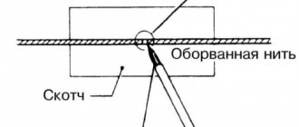
A special conductive adhesive is sold that is perfect for such purposes. It is used as follows: glue adhesive tape on both sides of the break in the track so that the gap between them is no thinner than the track.
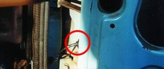
Broken thread. Inside view of the VAZ 2109
Then apply a thin layer of conductive glue at the break point, connecting the track, without waiting for the glue to dry, remove the adhesive tape from the rear window. Remember, if after applying the conductive adhesive the track still doesn't work, there is another break somewhere in that track.
In this simple and clear way you can restore the heated rear glass. Now, even in snow and rain, the rear window will be clean and transparent, providing the driver with excellent visibility.
Rear window heating of VAZ 2109 restored
If you live somewhere in the middle of nowhere and no one in your area has heard of conductive glue, then there are quite a few options for restoring rear window heating: starting from homemade adhesives with copper filings and graphite, and ending with fans for blowing the rear window. You can search the Internet and find what suits you.