Central unit of body electronics Lada Vesta and XRAY (description, reviews)
_x000D_
The electrical circuits of modern LADA cars are very different from previous AvtoVAZ models. Some of the relays have disappeared and instead they are replaced by an electrical package control unit (comfort unit), which is responsible for the operation of the ESP, central locking, turn relays, turn signals, etc.). Lada Vesta and XRAY use a similar CBKE module (central body electronics unit).
_x000D_
Heating, ventilation and air conditioning unit
Removing and installing the heating, ventilation and air conditioning system unit
1. Place the car in the workplace. Open the hood and disconnect the ground wire terminal from the battery (spanner 10).
2. Drain the coolant (see Chapter 7 “Cooling System”).
3. Unload refrigerant for cars with air conditioning, in accordance with the requirements of the equipment instructions.
4. Disconnect the heating system inlet and outlet pipes from the heater core and the air conditioning system piping block from the evaporator (see the corresponding section below in this chapter).
5. Remove the instrument panel frame (see Chapter 19 “Body”).
6. Unscrew bolts 2 securing cross member 1 of the instrument panel to the body (spanner 13).
Instrument panel cross member:
- instrument panel cross member;
- instrument panel cross member mounting bolt;
- housing of the heating, ventilation and air conditioning system
7. Unscrew bolts 2 securing unit 3 of the heating, ventilation and air conditioning system to cross member 1 (replaceable head 10, knob).
Mounting the heating, ventilation and air conditioning system unit:
- instrument panel cross member;
- mounting bolts for the heating, ventilation and air conditioning system unit;
- housing of the heating, ventilation and air conditioning system
Purpose and description
_x000D_
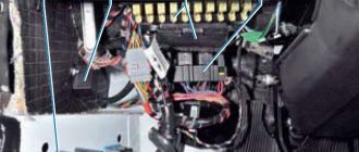
The central body electronics unit (CBEC) came from Renault and is located under the panel behind the glove box. The block is designed to perform the following functions:
_x000D_
- _x000D_
- Access control system functions;
- Starter control;
- Control of relays of additional consumers;
- Control of the rear window heater and electric side mirror heaters;
- Windshield defroster control;
- Control of direction indicator and hazard warning lamps;
- Interior lighting control;
- Control of door sill lamps (for the “Lux” package);
- Trunk lighting control;
- Windshield wiper control (for “Classic” and “Comfort” trim levels);
- Energy saving control of vehicle interior lighting devices;
- Monitoring the state of the brake signal switch (BST);
- Monitoring the state of the clutch pedal position signal switch (CPPS) (for configurations with a manual transmission);
- Indication.
_x000D_
_x000D_
_x000D_
_x000D_
_x000D_
_x000D_
_x000D_
_x000D_
_x000D_
_x000D_
_x000D_
_x000D_
_x000D_
_x000D_
_x000D_
Purpose and replacement of the body electronics unit of the Lada Khrey car
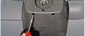
The body electronics unit is installed behind the instrument panel glove box.
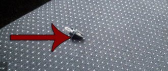
To access the unit, you need to unscrew the five screws securing the glove box.
The body electronics unit performs the following functions:
— access control system functions;
— starter control;
— control of relays of additional consumers;
— control of the rear window heater and electric side mirror heaters;
— control of the windshield heater;
— control of direction indicator and hazard warning lamps;
— control of the interior lamp;
— control of door sill lamps (for the “Lux” package);
— trunk lighting control;
— windshield wiper control (for “Classic” and “Comfort” trim levels);
— energy saving management of vehicle interior lighting devices;
— monitoring the state of the brake signal switch (BST);
— control of the clutch pedal position signal switch (CPPS) (for configurations with a manual transmission);
— indication.
Removal and installation (CBKE) of the central unit of body electronics
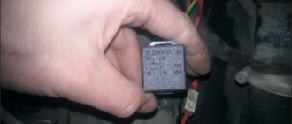
We prepare the car for work. Disconnect the negative terminal of the battery.
We dismantle the housing of the instrument panel glove box
We disconnect from TsBKE 1, Figure 1, four connectors 2 of the instrument panel wiring harness.
Using a socket 8, unscrew the nut 3 securing the TsBKE to the bracket 5 of the cross member of the instrument panel 6.
We disconnect the CBKE unit from the instrument panel cross member bracket and remove it from the car.
Install the TsBKE on the vehicle in the reverse order of removal.
After replacing the TsBKE, in order to restore its functioning, it is necessary, using the Grade-X diagnostic device, to perform the TsBKE training procedure (the procedure for entering parameters into the TsBKE) and perform the procedure for automatically configuring the TsBKE.
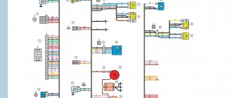
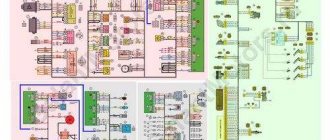
The electrical connection diagram of the TsBKE is shown in Figure 3 and Figure 4.
Functions of CBKE
2.1 Starter control
Power is supplied to the starter solenoid relay winding through the power contacts of the additional starter relay.
The CBKE turns on an additional starter relay when the ignition switch is moved to position “50”, if a signal to remove the engine start blocking has been received from the ECM.
The request to turn on the relay is sent to contact “A39” of the TsBKE from terminal “50” of the ignition switch. The additional starter relay is controlled from contact “B3” of the TsBKE.
The CBKE turns off the additional starter relay after the engine starts (the engine speed has reached 500-1000 rpm depending on the coolant temperature) or 7-20 seconds (depending on the coolant temperature) after the starter starts cranking. The CBKE prohibits the activation of the additional starter relay when the engine is running.
2.2 Control of relays of additional consumers
Power is supplied to the cigarette lighter through the relay contacts of additional consumers.
TsBKE turns on the relay of additional consumers when the ignition switch is moved to the “ACC” or “15” position.
A request to turn on the relay is sent to contact “A28” of the TsBKE from the “ACC” terminal of the ignition switch. The relay of additional consumers is controlled from contact “B4” of the TsBKE.
TsBKE turns off the relay of additional consumers when the ignition switch is moved to position “50” (see paragraph 2.1).
2.3 Control of rear window and side electric mirror heaters
The CBKE turns on the rear window heater relay when a request is received from the air conditioning control panel only when the car engine is running (the CBKE receives information about engine operation via the CAN bus from the ECM) and the vehicle's on-board voltage is not less than (10.8±0.2) V.
When you press the rear window heating switch located on the air conditioning control panel, the request is sent to contact “A14” of the CBKE from contact “A8” of the air conditioning control panel in the “Comfort” configuration, or via the CAN bus (contacts “A23”, “A24” of the CBKE ) in the “Lux” package. The rear window heater relay is controlled from contact “A34” of the TsBKE.
When the rear window defroster is switched on, the warning light in the switch lights up.
When you press the rear window heating switch again or when you stop the engine, the TsBKE turns off the rear window heating relay.
The electric side mirror heaters turn on and off simultaneously with the rear window heater.
2.4 Windshield defroster control
The CBKE turns on the windshield heater relay as well as the rear window heater relay when a request is received from the rear window heating switch (see paragraph 2.3) only when the car engine is running and the car's on-board voltage is not less than (12.8±0.2) V. The windshield heater relays 1 and 2 are controlled from contacts “B9” and “B6” of the TsBKE, respectively.
The on state of the heater is limited by a timer and is no more than (6±0.5) minutes. Pressing the switch again before the specified time has expired turns off the heater.
When the engine is stopped, the heater turns off; the next time the engine is turned on, the heater does not turn on.
Control of turn signal and hazard warning lamps
2.5.1 Control of direction indicators.
The turn indicators are turned on by the steering light switch when it is switched to the “Right turn indicators” or “Left turn indicators” mode.
A request to turn on the right turn indicators comes to contact “A22” of the CBKE from contact “A8” of the light signaling switch, a request to turn on the left turn indicators comes to contact “A1” of the CBKE from contact “A5” of the light signaling switch. The right turn indicators are controlled from contact “C5” of the TsBKE, and the left turn indicators are controlled from contact “C12” of the TsBKE.
The direction indicators only turn on when the ignition is on.
The direction indicator lamps are switched directly by the outputs of the TsBKE.
2.5.1.1 The switching frequency of lamps when in good condition is 90 ± 10 cycles per minute over the entire operating range of temperatures and supply voltage. The lamp duty cycle is 0.5 ± 10%.
2.5.1.2 When one or more lamps with a total power of at least 20 W burn out, the lamp switching frequency is 150 ± 10 cycles per minute on the board where the burnout is detected. The lamp duty cycle is 0.5 ± 10%.
2.5.1.3 When the turn signal is turned on briefly (non-fixed position), the lamps should flash 3 times and go out.
If the turn signal switch was turned on and off before the lamps flashed 3 times, then the lamps should flash 3 times after the steering column switch lever is moved to the “Off” position and go out.
If the turn signal switch was turned off after the 3rd flash of the lamps, then the lamps should go out or flash no more than once after the switch lever is moved to the “Off” position.
2.5.2 The hazard warning light turns on when you press the hazard warning switch, regardless of the state of the ignition switch, and the indicator on the hazard warning switch button flashes. Pressing the hazard warning switch again turns off the hazard warning lights. The hazard warning lights also turn on when the direction indicator is working.
The request to turn on the direction indicators is sent to contact “A8” of the TsBKE from contact “3” of the hazard warning switch.
The operation of the lamps when the alarm is turned on corresponds to clause 2.5.1.1.
2.5.3 Transmitting the state of direction indicators via the CAN bus.
The state of the direction indicators is transmitted via the CAN bus by the corresponding signal as part of the TsBKE message (see paragraph 2.13).
Interior lighting control
TsBKE controls the interior lamp if the lamp switch is set to the “Door control” position.
The interior lamp control is carried out from contact “C6” of the TsBKE.
2.6.1 When the ignition is turned off, as well as when the security mode is turned off from the remote control, the lamp turns on with a smooth dimming for 0.7 seconds for 20 seconds and turns off with a smooth dimming for 2 seconds if no door was opened.
2.6.2 The lamp turns on with a smooth ignition within 0.7 s when any side door is opened, regardless of the position of the ignition key.
2.6.3 After closing the last of the open side doors, the lamp continues to light with a “off delay” for 20 s, after which it goes out smoothly within 2 s, regardless of the position of the ignition key.
2.6.4 If during the “off delay” the alarm system is armed, the lamp will gradually go out within 2 s after the moment of arming.
2.6.5 When turning off the security mode from the remote control, the lamp lights up during the set “off delay” (see paragraph 2.6.3), if no door was opened.
2.7 Control of door sill lamps (for the “Lux” package)
CBKE controls the left threshold lighting lamp and the right threshold lighting lamp. The lamp control algorithm corresponds to the interior lamp control algorithm (see paragraph 2.6.1-2.6.5).
Trunk light control
The trunk light turns on when the trunk lid (tailgate) is opened. The lamp control algorithm corresponds to the interior lamp control algorithm (see paragraph 2.6.1-2.6.5).
2.9 Windshield wiper control (for “Classic” and “Comfort” trim levels)
The CBKE controls the windshield wiper in the “intermittent” mode. Control is only possible when the ignition is on.
When the wiper switch is turned to the intermittent position, the wiper blades begin to move at low speed.
Using the adjustment ring located on the wiper switch lever, you can set the pause duration of the intermittent mode to 1, 5, 10, 15 s.
The request to turn on the “intermittent” mode is sent to contact “A7” of the CBKE from contact “A8” of the wiper switch. The windshield wiper is controlled from contact “C1” of the TsBKE.
When the windshield wiper is turned off, the blades complete the started motion cycle and stop. The movement cycle is the movement of the brushes forward and return to the park position.
When the windshield washer is turned on, the wiper blades begin to move at low speed.
The windshield wiper performs 1 or 4 cycles of movement, depending on the operating time of the windshield washer:
1 cycle - when the windshield washer operates for no more than 1 s;
4 cycles (3 cycles in succession, pause, 1 cycle) - when the windshield washer operates for more than 1 s.
A request to turn on the windshield wiper when the washer is turned on is sent to contact “A15” of the CBKE from contact “A1” of the wiper switch.
The CBKE monitors the functionality of the windshield wiper park position limit switch using a signal that is sent to contact “C2” of the CBKE from contact “1” of the windshield wiper.
If the park position limit switch is faulty, instead of intermittent operation of the windshield wiper, it operates in the “low speed” mode.
2.10 Energy saving control of vehicle interior lighting devices
CBKE controls the supply voltage for interior lighting devices:
— interior lamp;
— individual lamps for the driver and passenger;
- glove box lighting.
The supply voltage of these devices is controlled from contact “C4” of the TsBKE.
When the ignition is turned off, the timing of applying voltage to the output of this circuit begins - the delay of the energy saving circuit.
The delay is 4 minutes if any door is not opened after turning off the ignition. If any door was opened after turning off the ignition, the delay is 2.5 minutes.
At the end of the delay, the voltage at the circuit output is turned off. After a power failure, the delay can be restarted by opening any door or turning the ignition on and off.
2.11 Monitoring the state of the brake signal switch (BST)
The brake signal switch has two groups of contacts, the first of which (contacts 3-4) switches the voltage from contact “C4” of the TsBKE to contact “A26” of the TsBKE, and the second (contacts 1-2) switches the voltage of terminal “30” to contact “D8” » TsBKE and to power the brake light lamp.
In parallel, signals from the VST are sent to the ECM. When the brake pedal is released, the contacts of the first group (3-4) should be normally closed, and the contacts of the second (1-2) should be normally open.
2.12 Monitoring the state of the clutch pedal position signal switch (CPPS) (for configurations with a manual transmission)
The switch switches ground to contact “A21” of the TsBKE. When the clutch pedal is pressed, the contacts are open. The clutch pedal position switch signal is used by the ECM software to improve the vehicle's driving performance.
Information about the status of the VSPPS is sent from the CBKE to the ECM via the CAN bus.
Indication
2.13.1 Indication by direction indicators.
The direction indicators are indicated as follows:
— when the sound and light alarm mode is activated in case of violation of any of the security zones;
— when the doors are locked from the remote control and the security mode is turned on at the same time - two short light signals from the direction indicators;
— when unlocking doors with the remote control and simultaneously turning off the security mode - with a single short light signal from the direction indicators;
2.13.2 Indication by a buzzer in the instrument cluster.
The CBKE transmits the turn signal status signal via the CAN bus to the instrument cluster, which displays it with a buzzer signal (indication by the turn signals is accompanied by buzzer signals).
2.13.3 Indication of direction indicators and hazard warning lights in the instrument cluster.
The CBKE transmits the turn signal status signal via the CAN bus to the instrument cluster, which displays it by flashing the turn signal indicators and hazard warning lights (indication by the turn indicators is accompanied by flashing warning lights).
2.13.4 Indication of high beam headlights in the instrument cluster.
The signal to turn on the high beam headlights is sent to contact “A19” of the TsBKE.
The CBKE transmits a signal via the CAN bus indicating the operation of the high beam headlights to the instrument cluster, which displays it by turning on the high beam headlight indicator.
2.13.5 Indication of low beam headlights in the instrument cluster.
The signal to turn on the low beam headlights is sent to contact “A37” of the TsBKE.
The CBKE transmits a signal via the CAN bus indicating that the low beam headlights are operating to the instrument cluster, which displays it by turning on the low beam headlight indicator.
2.13.6 Indication of side lights by the signaling device in the instrument cluster.
The signal to turn on the side lights is sent to contact “A20” of the TsBKE.
The CBKE transmits a signal via the CAN bus indicating the operation of the side lights to the instrument cluster, which displays it by turning on the side lights indicator.
2.13.7 Indication of rear fog lights by a signaling device in the instrument cluster (for “Classic” and “Comfort” trim levels).
The signal to turn on the rear fog lights is sent to contact “A16” of the TsBKE.
The CBKE transmits a signal via the CAN bus indicating the operation of the rear fog lights to the instrument cluster, which displays it by turning on the rear fog light indicator.
2.13.8 Indication by a signaling device of open doors in the instrument cluster.
The CBKE transmits a signal via the CAN bus indicating that the front passenger door, driver's door and rear passenger doors are open to the instrument cluster, which displays it by turning on the door open indicator.
2.13.9 Indication of an open hood indicator in the instrument cluster.
The CBKE transmits a signal via the CAN bus with a sign of an open hood to the instrument cluster, which displays it by turning on the hood open indicator.
CBKE schemes
_x000D_
_x000D_
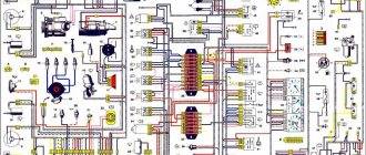
Electrical connection diagram for TsBKE on LADA VESTA: 2 – rechargeable battery; 3 – starter; 4 – rear left outer lamp; 5 – left headlight; 7 – rear window heating relay (K3); 8 – right headlight; 10 – rear outer right lamp; 13 – trunk light; 15 – fuse 60 A (F70); 16 – additional relay (K8); 17 – ignition switch; 26 – alarm switch; 30 – fuse 5 A (F20); 32 – left steering column switch (light alarm switch); 34 – fuse 60 A (F75); 35 – rear window heater; 44 – windshield heating relay 1 (K21); 46 – windshield heater; 47 – lampshade lighting of the glove box; 48 – switch for the glove compartment lamp; 51 – TsBKE (VSM controller); 58 – fuse 30 A (F61); 59 – left threshold lamp (installed on luxury equipment); 60 – right threshold lighting lamp (installed on the “luxury” configuration); 61 – relay of additional consumers (K2); 63 – fuse 10 A (F32); 84 – fuse 3 A (F43); 87 – left outside mirror; 88 – right outside mirror; 120 – additional starter relay (K23); 134 – brake signal switch; 138 – fuse 5 A (F15); 164 – air conditioner control panel (connection diagram for the “comfort” package); 185 – interior lighting unit with ERA-GLONASS interface module; 196 – fuse 5 A (F24); 200 – fuse 15 A (F11); 201 – fuse 15 A (F12); 202 – fuse 10 A (F13); 203 – fuse 10 A (F14); 204 – fuse 5 A (F17); 205 – fuse 5 A (F16); 229 – fuse 3 A (F49); 230 – clutch pedal position signal switch; 231 – windshield heating relay 2 (K22); 233 – fuse 5 A (F80)
_x000D_
- _x000D_
- location of fuses F1-F59 and relays K1-K20 in the interior mounting block;
- location of fuses F60-F80 and relays K21-K28 in the motor mounting block
_x000D_
_x000D_
_x000D_
_x000D_
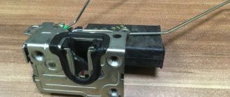
Electrical connection diagram for TsBKE on LADA VESTA car (Comfort package) : 2 – rechargeable battery; 3 – starter; 9 – rear inner left lamp; 15 – fuse 60 A (F70); 16 – additional relay (K8); 17 – ignition switch; 20 – fuse 15 A (F1); 23 – rear inner right lamp; 28 – fuse 5 A (F74); 31 – reverse light switch; 33 – right steering column switch (windshield wiper switch); 51 – TsBKE (VSM controller); 63 – fuse 10 A (F32); 79 – electric motor for windshield wiper; 80 – washer motor; 120 – additional starter relay (K23); 198 – fuse 25 A (F40);
_x000D_
- _x000D_
- location of fuses F1-F59 and relays K1-K20 in the interior mounting block;
- location of fuses F60-F80 and relays K21-K28 in the motor mounting block
_x000D_
_x000D_
_x000D_
After replacing the TsBKE, it is necessary to perform the training procedure (entering parameters) and automatic configuration of the TsBKE using the Grade-X diagnostic device. You can also view error (fault) codes using this device. You can get acquainted with the functionality of the CBKE in more detail, as well as its diagnostics, using the TI (device, fault diagnosis of the CBKE).
_x000D_
On the one hand, this functional device allows you to more finely tune the operation of the electronics. On the other hand, the unit has a complex structure, which makes independent repairs more problematic. If the TsBKE fails, you will have to contact the dealer, because It is unlikely that the necessary equipment for programming or diagnostics will be at hand.
_x000D_
Attention! It is impossible to retrain a CBKE taken from another vehicle.
_x000D_
Which implementation do you like best? The presence of a simple circuit, where there are turn relays, ESP, etc., or the presence of a central electronics control unit? Find other materials on repair, maintenance, modifications and tuning of these cars in the contents (XRAY crossover, Lada Vesta sedan).
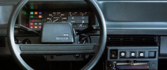
Instrument panel diagram Kalina 2
1,2 – blocks of the instrument panel wiring harness to the blocks of the front wiring harness; 3, 4 — blocks of the instrument panel wiring harness to the blocks of the rear wiring harness; 5 – lighting control module; 6 – ignition switch; 7 – on-board computer mode switch; 8 – windshield wiper switch;
9 – instrument cluster; 10 – light signaling switch; 11 – trunk lock drive switch; 12 – diagnostic block; 13 – block of the instrument panel wiring harness to the block of the wiring harness of the air supply box; 14 – rear window heating switch; 15 – alarm switch;
16 – brake signal switch; 17 – multimedia system; 19 – rotating device; 20 – driver airbag module; 21 – sound signal switch; 22 – mounting block: K1 – relay for the electric fan of the engine cooling system; K2 – door lock relay;
K3 – additional starter relay; K4 – additional relay; K6 – windshield wiper relay; K7 – headlight high beam relay; K8 – sound signal relay; K9 – relay for low beam headlights; K10 – relay for turning on the heated rear window; K11 – main relay; K12 – fuel pump relay; 23 – electric power steering;
24 – cigarette lighter; 25 – lampshade lighting of the glove box; 26 – glove box lighting switch; 27 – block of the instrument panel wiring harness to the block of the ignition system wiring harness; 28 – engine control system controller; 29 – block of the instrument panel wiring harness to the block of the rear wiring harness 4;
Read more: BMW M5 E28 E34 E39 E6061 F10 review of the fifth series price specifications photos and videos test drive
30 – electronic accelerator pedal; 31 – additional resistor; 32 – heater electric motor; 33 – solar radiation sensor; 35 – relay (K13) of the electric fan of the engine cooling system 3; 36 – compressor relay (K16); 37 – relay (K14) for heating the windshield; 38 – relay (K15) for heating the windshield 2;
39 – headlight range control regulator; 40 – clutch pedal position signal switch; 41 – passenger airbag module; 42 – evaporator temperature sensor; 44 – windshield heating element; 46 – windshield heating switch; 47 – central unit of body electronics;
By the way, do you know how to apply these schemes in
All other schemes are suitable for the “norm” and “standard” configurations.
Video about climate control of Lada Vesta
Both Vesta and Xray, as well as other AvtoVAZ models, are equipped with air conditioning or climate control, depending on the configuration. Many people confuse these concepts, or for some they are the same thing. But the truth is a little different than some people think.
Air conditioning is a system capable of supplying cold air to a car. The structure of the air conditioner: compressor, radiator with freon, temperature sensor.
Climate control is a whole system for controlling the air temperature in the cabin. In addition to the fact that it can cool the temperature (a conventional air conditioner), it can also maintain a constantly set temperature by regulating air flows, the speed of the stove fan, and the direction of air flows.
In other words, an air conditioner is a refrigerator that can only cool, while climate control is a whole system that can constantly maintain a set temperature.