During engine operation, natural wear and tear occurs on its rubbing and contacting parts, including valves, rockers, and camshafts. The gap in the camshaft cam-rocker valve drive increases, and knocking and clicking noises appear. They call it “valve knock”. It is clearly distinguishable against the background of other noises, is heard at regular intervals, and its frequency is less than the frequency of any other knock in the engine. Sometimes this valve knocking noise disappears completely after the engine warms up. If you have this clicking noise, it’s time to think about adjusting the thermal gap (later adjusting the valves) between the rocker and the camshaft cam. It is better to time the valve adjustments to coincide with changing the engine oil. Why? Dust, dirt, sand that accidentally gets into the engine during adjustment will be removed along with the old oil and oil filter.
Thermal clearances are checked and adjusted on a cold engine. For the intake valves (2, 3, 6, 7) we set the gap to 0.15 mm, and for the exhaust valves (1, 4, 5, - 0.2 mm. It is not at all necessary to memorize which intake and which exhaust valves, just look on the intake and exhaust manifolds.Intake valves will be located opposite the intake manifold pipes, and exhaust valves will be located opposite the exhaust manifold pipes.
Try to set the gap as accurately as possible. With a large gap, severe wear of the rocker, camshaft cam and valve end occurs, and with a small gap, the valve plates burn out. Before adjusting the valves, you must first check the fastening of the camshaft bearing housing, the alignment of the marks on the crankshaft pulley and the camshaft sprocket, and tighten the chain.
You can adjust it in two ways, using probes or using a special device with a micrometer. Adjusting with feeler gauges is a long and imprecise operation. Uneven surfaces between the rocker and the camshaft cam are not taken into account; accordingly, the gap will be plus or minus a kilometer. Therefore, it is better to give preference to a bar with a micrometer. All eight valves can be adjusted easily, accurately and quickly within 18-22 minutes. It is impossible to make a mistake in the adjustment order, since the valve number is indicated on the bar and at what angle the crankshaft must be turned to adjust it. Even a beginner can easily handle the procedure.
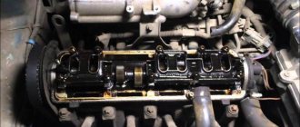
1. Disconnect the crankcase gas hose from the air filter housing. 2. Unfasten the 4 latches and unscrew the nut 10 of the air filter housing cover. 3. Unscrew the 4 nuts 8 securing the air filter housing and remove it. Cover the carburetor with the service cover. 4. Disconnect from the carburetor: the choke cable, the crankcase exhaust hose, the fuel return line, the transverse link from the throttle valve drive lever and the longitudinal link from the return spring lever, removing the mounting bracket. 5. Disconnect the brake vacuum hose from the vacuum booster. 6. Remove the high-voltage wires from the ignition coil and spark plugs. 7. Unfasten the latches of the sensor-distributor cover and remove it along with the wires. 8. Remove the spark plugs. 9. Pull out the oil dipstick. 10. Unscrew the eight nuts 10 securing the valve cover. Remove the brackets and clamp washers. 11. Remove the valve cover. Lift it above the cylinder head so that it is removed from the studs, lift the back, then the front. 12. Check the tightness of the nuts (9 pieces) securing the camshaft bearing housing:
If necessary, tighten them with a torque of 18.3-22.6 N. m. If the thread on the stud is broken, replace the stud. If the threads in the cylinder head are stripped, cold weld the stud and allow time for the stud to harden firmly. 13. Check the alignment of the marks on the crankshaft pulley and the camshaft sprocket. Mark 4 on the crankshaft pulley should be opposite the lower, long mark 3 on the front engine cover, and the mark on the camshaft sprocket should be opposite the boss of the bearing housing, the contact on the rotor is directed towards the electrode of the fourth spark plug on the distributor cover:
A little theory
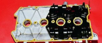
The main difference between rockers for the field “Made in USSR” and “Made in Russia” is the material. According to Soviet metal classification and state standards, cast iron was divided into two large categories. Cast iron of the highest quality, KCH - malleable cast iron. And the rest, the warhead, is white cast iron. These materials differed not only in specific gravity, but also in crystal structure. Frames for machine tools, engine blocks, and gearbox housings were made from CP. From warheads - weights, counterweights, manhole covers.....and other important details))) As you might guess, the old rockers are made from warheads, the new ones from warheads))) Well, since nothing can be done in this case, let's move on to specifics at the moment .
Old and new standard
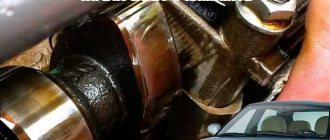
There is only one difference. This is the diameter of the landing ball on the soldier and, as a result, the different diameter of the rocker hole. Old-style rockers were installed on the assembly line somewhere up until 2008-2010. exclusively on engines 21213. Even on the classics at that moment, soldiers and rockers with small balls were installed. The photo clearly shows how different the diameter of the ball is. And one more very important point is the rocker profile. The camshaft lobe should "roll" onto the rocker, not strike. Only in this way can you achieve quiet engine operation and high-quality adjustment.
The “death to hydraulics” kits are equipped with a new type of rockers. That is, the soldier comes with a small ball.
Valve VAZ 2106
Recently I had to adjust the valves again... I'm a little tired of them already, I probably need to replace the rocker and camshaft. But this post is not about that, although soon there will be a post about replacing rockers. And since I had to adjust the valves once again, I want to give good instructions on how to properly adjust the valves on a VAZ 2106. It is worth noting that in this version the adjustment is made using a feeler gauge. The dipstick is a factory option, but on rather worn engines it does not provide the required accuracy. Another thing is the adjustment rail.
Adjustment
To begin with, I will give a list of tools that will be needed to complete this work with the VAZ 2106.
Open-end wrench 13
17 open-end wrench
A set of probes, or rather, we need exactly one probe, 0.15 mm thick
And also a list of tools needed to remove the valve cover
Step-by-step guide to adjusting valve clearances
Before starting this work, it is worth considering that the car engine must be cold, that is, its temperature should be as close to room temperature as possible. It is also worth noting that the timing chain tension should be normal.
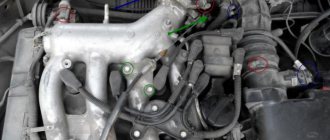
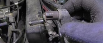
The first step is to remove the valve cover. After this, align the crankshaft and camshaft pulley according to the marks. If the chain was put on correctly, then the marks should match, but it’s still better to check it again. So, the mark on the crankshaft pulley should match the long mark on the front engine cover. This is how everything looks visually:
I specially made it closer so that it could be seen better:
Now we look at the camshaft sprocket and there, too, the mark on the gear should coincide with the protrusion on the cover. The photo below shows everything:
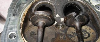
With this position of the crankshaft and camshaft, the piston of the fourth cylinder is at top dead center (TDC). It is at this moment that it is necessary to adjust the clearance of the 6th and 8th valves. If this is your first time, keep in mind that the valve numbers are counted from the left side, that is, from the front of the engine. To understand which valves need to be adjusted in this position, I will show you everything, literally:
Now we take a feeler gauge 0.15 mm thick and insert it between the rocker and the camshaft; the photo below shows all this more clearly using the example of the 8th valve:
If the feeler gauge passes without effort, then the gap is too large and needs to be made smaller. If, on the contrary, the dipstick does not pass between the rocker and the camshaft of the VAZ 2106, then the gap must be reduced to 0.15 mm. The gaps are adjusted using an adjusting bolt and a control nut as follows. First, slightly loosen the locking nut with a 17 wrench, and with a 13 wrench we set the required gap by unscrewing it or, on the contrary, tightening it.
Rocker Pilenga
When Pilenga's rockers went on sale, questions immediately started pouring in. Quote. *I installed a set of rockers, adjusted them several times, everything still rumbles, etc.* End of quote. I explained the secret above. Rocker Pilenga are really good, but they are of the old type, with a hole for a large ball. Naturally, they fit easily on a small one, only the rocker dangles on the ball, like a pencil in a glass. There can simply be no talk of any regulation. But the Fiat cannot be broken so easily and the engine, even with such abuse, continues to work.
Design and principle of operation of rockers
The rocker design is a lever with two arms - short and long. Between them there is an axial hole, relative to which the rocker moves during operation. One end of the lever is connected to the valve stem, the other to the pusher. In the operating cycle, the pusher acts on one arm, and the other arm pushes the valve.
The rocker design also provides for various adjustment mechanisms (screws), technological channels and holes in order to provide lubricant to the moving structures of the timing elements.
Rockers can be made in several ways - casting, stamping or forging. It is believed that forged rockers are stronger and more reliable than others due to the specific technological processing.
Rockers, or rocker arms in a car
- Rockers, or rocker arms in a car
- Rocker device.
- Operating principle of valve rocker arms.
- Common breakdowns.
It happens that when repairing a car, it is necessary to replace or repair the rocker.
Many people, encountering this problem for the first time, do not know what it means. Rockers (or valve rockers as they are also called) are a mechanism used to transfer energy from the camshaft cam to the intake valve stem. Valve rocker arms are part of the gas distribution mechanism (GRM) of a car engine with a “classical” structure. Nowadays, rockers in engines are quite rare. The reason for this is the fact that modern engines have completely moved to overhead camshafts. And, as a rule, the main reason for using rockers in modern engines is the desire to reduce the size of the latter. There may be several reasons for making such a decision, but the first place is occupied by the need to place an internal combustion engine (ICE) under the hood of a small car.
Rocker device.
A rocker is a lever with two “shoulders”, and it is made by forming steel using forging or casting technology. If you choose, the forging method is much better, because forged parts are incomparably stronger. Both “shoulders” of the rocker have a T-shaped section.
Traditionally, there are long and short arms of the rocker arm. At the end of the long arm there is a hardened cylindrical plane - the rocker striker. The striker of the rocker rests against the end end of the valve stem.
At the end of the short arm there is a bolt with which the depth of the gap between the valve itself and the valve drive lever is adjusted. If there is a hydraulic compensator, this gap is adjusted automatically. At the same time, the noise is significantly reduced, and the operation of the timing belt becomes smoother and softer. There is also a special hole in the short arm, which provides access to engine oil for lubricating parts.
The rocker arm is restrained by a coil spring. This is necessary in order to prevent the rocker from moving along the axis. The axle itself, which serves to attach the rockers, is hollow, and the outer side of the axle is hardened, which increases wear resistance.
Operating principle of valve rocker arms.
The principle of operation of the rocker arm is as follows: when the camshaft cam puts pressure on the short arm, lift occurs.
The long arm lowers, while pressing on the valve stem. Auxiliary elements in the rocker structure are bushings that reduce friction.
Common breakdowns.
Since during operation the rocker striker and the rocker itself are subjected to various thermal and mechanical loads, this, in turn, leads to their damage and wear.
If you notice that the output from the internal combustion engine is decreasing in different operating modes, or you hear a characteristic knocking sound in the cylinder head, this means that the rocker is broken.
Also, very often the rocker itself breaks, which means that the valve has failed. External signs of a broken rocker are exactly the same as in the case of a malfunction of any timing part.
Subscribe to our feeds on social networks such as Facebook, Vkontakte, Instagram, Pinterest, Yandex Zen, Twitter and Telegram: all the most interesting automotive events collected in one place.
Maintenance and typical faults of rockers
Rockers do not require frequent maintenance. It is quite enough if, when carrying out service work on other elements of the timing mechanism, their current condition is assessed - the absence of visible mechanical damage and signs of critical wear. If no problems are identified, then they can be used further. But only after thorough cleaning of contaminants.
Rocker failures, although they do not occur very often, can lead to serious problems with other engine components. For example, a broken rocker arm can lead to the failure of the corresponding valve. A sign of a breakdown may be a drop in engine power during normal operation and the appearance of a characteristic knocking sound in the cylinder head.
If you need to install new rockers, you need to select them only according to the original catalog and VIN code. No other catalogs will be suitable, as they cannot guarantee applicability. If buying original rockers seems like an expensive pleasure to you, then when you search by original article number, the system will offer you a set of analogues of various price categories.
We recommend watching:
- Adjusting valves VAZ 21 213
- Setting up Niva Chevrolet valves
- Distributor Breaker Maintenance
- How to adjust the carburetor on oka 1111
Checking valve clearances
There is a knocking sound when starting the car
Valve rocker
SONY DSC
Rocker (valve drive lever) is a structural element of the valve drive mechanism. There is also the name roller lever or rocker arm. The purpose of the rocker is to transfer force from the camshaft cam to the valve stem (rod) with an overhead camshaft position. This solution in the valve drive device provides the timing belt with less weight and reduces friction.
The rocker arm (valve rocker) absorbs the forward movement of the pusher rod and transmits this movement to the valve stem. The initial force is transmitted from the camshaft cam. The rockers are located at the top of the cylinder head. An axle is pressed into the central part of the rocker, the position of which is fixed using two rocker support pins. The support pins are inserted into special racks, which in some design options are made in the cylinder head housing.
The rocker arm, on one side, rests on the valve stem, and on the other, it can rest on the hydraulic compensator. Some designs of the valve drive mechanism provide for the rocker to rest on a special ball joint. The contact point between the rocker and the distribution cam is made in the form of a roller.
Valve rocker arms in modern engines are gradually being eliminated from the timing device due to the active use of overhead camshaft designs. The main purpose of using rockers today is to reduce the size of the engine. This may be necessary to place the internal combustion engine in the engine compartment of a small car.
A rocker is a lever that has two “shoulders” (a double-arm lever). The valve rocker arm is made by forming steel, casting or forging. The latter option is more preferable, since forged elements have increased strength. Forged rockers are installed on powerful power units.
It is customary to distinguish between the long and short arms of the rocker arm. The long arm has a special reinforced cylindrical surface. This surface is commonly called the rocker striker. With its striker, the rocker arm receives emphasis on the end end of the valve stem. At the end of the short arm of the valve rocker arm there is an adjusting bolt, which allows you to adjust the depth of the gap between the valve and the valve drive lever. If there is a hydraulic compensator, then the thermal gap is adjusted automatically, reducing noise and making the timing smoother.
A hydraulic compensator (hydraulic pusher) is a cylinder that is based on a piston with a spring, a check valve and special channels for supplying engine oil from the internal combustion engine lubrication system. If the hydraulic compensator is located on the valve tappet, the device is called a hydraulic tappet (hydraulic tappet).
Additionally, there is a hole in the short arm that provides access to engine oil to lubricate the elements. To prevent the rocker from moving along the axis, the rocker arm is held in place by a coil spring. The rocker arm works on the following principle: when the camshaft cam exerts force on the short arm of the rocker, thereby lifting occurs. The long arm moves down, pressing on the valve stem. Additional elements in the rocker design are bushings to reduce friction.
During operation, the rocker striker, bearings and the rocker itself are subject to mechanical and thermal loads, which leads to wear and damage. The rocker arm may break, which means the valve stops working. If the rocker breaks, then the malfunction manifests itself in the form of a characteristic knocking sound in the cylinder head and a decrease in output from the internal combustion engine in various operating modes.