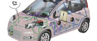
How to check the generator on site
There are main reasons for poor starting of an internal combustion engine; the starter turns poorly if:
- the battery is old or faulty, does not charge and does not hold a load;
- battery cables do not provide reliable contact, for example, due to oxidized terminals;
- there is no reliable mass of the engine with the body;
- the generator does not provide the required charge;
- The drive belt is weakly tensioned, because of this the generator rotor does not rotate at full strength, since the belt slips under load.
There are different types of generator failures, the most typical of which are:
- breakage of wires approaching the node;
- breakdown of the diode bridge;
- malfunction of the relay regulator;
- short circuit (burnout, break) of the rotor or stator winding;
- bearing wear;
- brushes wear out or break.
The worst thing that can happen is that the bearings jam or the windings burn out, but in this case it’s easy to check the generator’s functionality; its condition can be easily determined by external signs:
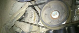
- The generator pulley and shaft do not rotate when the engine is running;
- a specific smell of burnt windings appeared.
The main ways to check a generator on site are an external inspection of the parts of the generator assembly and measuring the voltage (U) with a multimeter (voltmeter). With the engine running under load, the voltage should drop slightly, but only to a certain value; if it is below normal, it is necessary to specifically deal with the generator device.
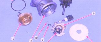
Generator maintenance involves periodically checking and adjusting the drive belt tension, as well as checking the condition of the brushes and slip rings of the generator.
The tension of the alternator drive belt is checked and adjusted during each vehicle maintenance. The condition of the brushes and slip rings should be checked at least every 60,000 km of the vehicle, and when driving on dirty and dusty roads - every 30,000 km. To check the brushes and slip rings, it is necessary to remove the brush holder by unscrewing screw 17 (see Fig. 276). Through the hole in the cover 12, in which the brush holder is located, the slip rings are clearly visible. The brushes should move freely, without jamming, in the brush holder. Their height must be at least 8 mm, counting from the location of the spring. If the brushes are more worn, they should be replaced along with the brush holder. The brush springs must be intact. If there are burns on the rotor slip rings, it is recommended to carefully clean the rings with fine-grained sandpaper.
Periodically check the reliability of the ground connection between the engine and the body (the ground wire is connected to the clutch housing). The fastening of the wire must be reliable, and the flexible wire itself must be intact. You can check the reliability of the connection by connecting a voltmeter between the engine and the negative pole of the battery. With the engine running at medium engine speeds and the headlights on, the voltmeter should not show a voltage drop. Possible malfunctions of the generating set, their causes and solutions are given in table. 28.
Control checks
Testing the generator on a stand allows you to determine the serviceability of the generator and whether its characteristics correspond to the nominal ones. To do this, the generator is installed on a stand along with a pulley.
Rice. 280. Connection diagram of the generator on the stand for recording the output current curve: 1 - generator; 2 - switch; 3 - ammeter; 4 - battery; 5 - rheostat; 6 - voltmeter; 7 - valves; 8 - stator winding; 9 - rotor winding
Rice. 281. Output current curve at steady thermal conditions and voltage 14 V
The stand should have an engine that allows you to change the rotation speed, a tachometer to measure the rotation speed of the generator rotor, an ammeter with a voltmeter, a rheostat to change the load and a battery.
The generator is checked in the following order.
Turn on switch 2 (Fig. 280) and rotate the generator rotor for 30 minutes at a frequency of 5000 rpm and with a load of 42 A at 14 V.
Take the output current curve at a constant voltage of 14 V (the voltage is set by rheostat 5). The current is measured first at 5000, and then at 4000, 3000 and 2000 rpm of the generator rotor, and each time the measurement must be done at the steady-state thermal regime of the generator, when the temperature of the generator housing does not change. To do this, the generator is kept at 5000 rpm for at least 1.5 hours, and at 4000, 3000 and 2000 rpm for at least 20 minutes. Determine the initial rotation speed of the generator rotor at which a voltage of 14 V is reached (the starting point of the curve in Fig. 281). To do this, gradually reduce the rotor speed until the output current reaches 1-2 A. Then open the contacts of switch 2 and, adjusting the speed, bring the voltage to 14 V.
At the stand you can also check the initial recoil voltage at 1000 rpm, which can also be used to judge the serviceability of the generator. For this check, the generator brushes must be well ground to the commutator slip rings, and the rings themselves must be clean. The excitation winding of the generator must be powered from the battery, the load and battery must be disconnected from terminal <30>, and the generator itself must be warmed up. The rotor speed is increased to 1000 rpm and the voltage between clamp <30> and the generator housing is measured. If the measured values of the supplied current are less than the values of the curve shown in Fig. 281, or the initial recoil voltage at 1000 rpm is less than 12.5 V, then this indicates a malfunction in the stator and rotor windings, damage to the valves or wear of the slip rings and brushes. In this case, a thorough check of the windings and valves is necessary to determine the location of the fault.
The serviceability of the valves and stator windings can also be checked by connecting two lamps of 3 W each to the generator: one between the zero point plug and the housing, and the other between this plug and terminal <30> of the generator (see Fig. 279). In a working generator, with serviceable valves and stator windings, both lamps should burn with the same intensity.
Read more about repair and maintenance of VAZ cars...
Checking the generator with a multimeter
The functionality of the generator without removing it from the car is checked according to the same principle, regardless of the car model, be it a foreign car or a VAZ-2106. In this case, it is not necessary to connect a multimeter to the generator connectors; you can measure the voltage directly on the battery. We check the generator with a tester as follows:
- with the engine turned off, connect the multimeter probes to the battery terminals, the black wire to the minus, the red wire to the plus;
- turn on the measuring device - set the switch to measure direct voltage with a maximum limit of 20 Volts;
- on a working battery, the tester should show U from 12.5 to 12.8 V;
- we start the engine, check the voltage readings again, with normal charging it should increase to approximately 14 V (ranging from 13.8 to 14.5 Volts);
- we turn on the additional load (headlights, heater motor at maximum position, radio, etc.), take measurements again;
- when the internal combustion engine is running at idle speed, U should not fall below 13.7-13.9 V; if the voltage is lower, the generator must be removed and more thorough diagnostics carried out.
Connecting the VAZ 2107 generator
The procedure for replacing a generator on a VAZ 2107 consists of its removal, installation, and connection. To dismantle the generator, follow this algorithm:
1. Be sure to turn off the power to the car by removing the negative terminal from the battery.
2. Next, disconnect the connector from the generator.
3. Having removed the protective cover, disconnect the terminal with a “10” key, and then remove the wire.
4. After loosening the generator, remove the drive belt.
5. Using a 17mm wrench, unscrew the nuts and remove the adjusting bar.
6. After unscrewing the lower mounting nut, remove the bolt and bushing.
7. You can dismantle the generator.
Install the new generator in reverse order. Before you begin installing the generator device, we recommend that you familiarize yourself with the electrical connection diagram for the VAZ 2107 generator.
Connection diagram for the VAZ 2107 generator
Numbers from 1 to 6 indicate the main elements of the power supply system:
mounting block with relays and fuses.
measuring device for monitoring voltage.
battery charge indicator lamp.
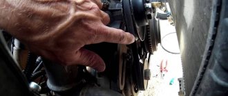
Adjusting the tension of the generator belt
After installation, the belt tension should be adjusted. To do this, loosen the 2 bolts securing the unit. Using a pry bar, tighten the belt and secure it with a nut on the adjustment plate. Next, check the degree of tension by lightly pushing the belt in between the pulleys.
The deflection should be between 10 and 17 mm. Please note that the tension procedure must be repeated until the correct value is obtained. Having optimally tensioned the belt, finally tighten all the fastening nuts. At this point, the connection of the generator can be considered complete.
Checking charging with the terminal removed
Removing the battery terminal while the engine is running is an old, proven method of checking the functionality of the generator; this method was used on Soviet cars. We check like this:
- start the engine;
- disconnect the negative terminal and move it to the side;
- if the engine turns off, it means there is no charging, you need to deal with the generator;
- Without installing the terminals, we add speed, the internal combustion engine should not stall.
You should also pay attention to this point - when installing the negative wire in place while the engine is running, the idle speed should not change noticeably. A significant decrease in speed indicates that the battery is quite discharged, and attention should be paid to this. A discharged or faulty battery may fail on the road; it is better not to travel with such a battery.
An important point is that you need to remove the terminal with the engine running very carefully; the wire should not touch live parts of the car (body, engine housing, etc.). On many modern cars, it is generally not recommended to disconnect the terminal while the internal combustion engine is running; if there is insufficient confidence in the test results, it is better not to use this method.
It is worth noting that there is still a way to check with a test light, but we will not consider this method - the lamp only indicates the presence or absence of charging, with its help it is impossible to determine the value of the voltage in the network and its dependence on the load.
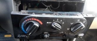
Signs of a weak alternator charge
In order to understand that the generator does not provide normal charging, it is not necessary to take measurements; the malfunction can be determined by various signs:
- while the engine is running, the charging indicator lamp on the instrument panel blinks or lights up;
- under load (turning on headlights, rear window heater, etc.), engine speed drops;
- the headlights burn dimly, this is especially noticeable when the high beams are turned on;
- When the engine speed increases, a whistle is heard, the cause of which is a loose drive belt, so charging also drops.
The on-board power supply indicator lamp must light up when the ignition is turned on and go out when the engine is running. If the instrument panel light does not light up at all, it may be burnt out and need to be replaced. Light indicators are now installed on almost all modern cars; previously, voltmeters were mainly used to monitor the state of the electrical network. These meters have ceased to be used due to the large error in the readings: it is difficult to determine from the voltmeter on the instrument panel exactly what kind of charging the generator is providing, but the warning lamp is difficult not to notice if it lights up.
Causes of battery undercharging
A car battery is an energy storage device: while the engine is running, it is charged from the generator, and then gives its energy to the starter to start the internal combustion engine. If the battery is not fully charged, it cannot provide normal cranking to the starter, causing problems:
- the engine does not start or starts with great difficulty;
- when the headlights or other consumers are turned on, the light on the instrument panel dims;
- the car has to be started by various unpopular methods - from a pusher, from a tow, by lighting it with another battery.
When there is undercharging, the indicator lamp on the instrument panel lights up at half intensity, the main reasons for this phenomenon are as follows:
- there is damage in the diode bridge - one of the diodes is broken;
- the relay-regulator (RR) is faulty;
- The generator brushes are worn out, or they do not fit tightly to the ring at the end of the armature (there is no reliable contact).
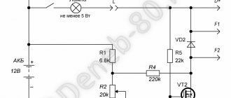
The voltage regulator (relay), more often than other parts, is the cause of this malfunction; it is one of the most vulnerable parts in the electrical part of the machine. To check or replace the relay-regulator, you often have to remove the entire generator assembly, but there are many car models where the removal and replacement of the RR can be done on site, without dismantling the generator assembly.
How to check the serviceability of the VAZ 2107 generator?
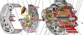
First, let's find out what the generator consists of, in principle. With some exceptions, all car generators have a similar list of components:
- Rotor . This is the part of the generator that rotates.
- Stator . It is also the housing on which the capacitor and contact terminals are mounted. Bearings for the rotor are also firmly mounted in the housing.
- Front and back covers . Removable, provide access to the “insides” of the generator.
- Voltage regulator . It can be built-in (integrated into the design) or replaceable.
- Mounting points.
The main generator malfunctions are of the same type, as are the methods for eliminating them. It is well known that when the charge current is insufficient, when the arrow is in the initial sector of the scale, the first thing to do is check how the generator drive belt is tensioned. If it slips, the pulley will not be able to rotate properly. If the generator fuse is intact and the drive belt is tight, it is worth checking the following points:
is there a break in the conductors from the generator terminal marked “30” to the contact marked “15”;
brush holder mounting screw. A short circuit may occur as a result of wear of the plastic fasteners;
whether the commutator group is dirty, whether the generator brushes are worn out;
Is there a short to ground in the generator excitation winding? It is checked with a tester (multimeter) in the “circuit ringing” mode;
You can also check for an open (or short circuit) of the diode group of the rectifier unit.
If the voltmeter needle is always in the red sector of the maximum current, you need to find out if there is any unwanted contact between the brush bus and the brush holder mounting screw. In addition, it is possible that the generator voltage regulator does not perform its function, which means it requires replacement.