Probably, hardly anyone will argue with the fact that the VAZ “ten” is not the pinnacle of design thought. However, there is nothing surprising here, because this car was designed back in the last century. At the same time, the compensator, and quite a serious one, in this case is the price. In other words, a certain compromise is proposed - the imperfection of the car in exchange for an acceptable cost. Well, the choice is ultimately made by the car owner himself, deciding whether this option is suitable for him.
You can talk about the advantages and disadvantages of this model for quite a long time. However, this is not what we are talking about now. Those who decide that the “ten” is a suitable option in terms of the ratio between price and quality often want to somewhat refine their iron horse during operation, making changes to both the exterior and the interior.
If we talk about tuning the car interior, then one of the main objects of improvement here is the dashboard. Many people simply don’t like the native version, which, frankly, doesn’t look very attractive. Yes, after the “Zhiguli” this is an undoubted step forward, but it’s already the 21st century outside the window, and I want something more beautiful and pleasing to the eye.
Why you should know the pinout
But before you start this kind of upgrade, you need to understand which wire leads where. The pinout of the instrument panel of a VAZ-2110 car is a very important point when “tuning”. Without this, you risk simply getting confused in a fairly large number of wires, buttons and various sensors. The pinout will be useful in any case - both when making minor improvements and when completely replacing the instrument panel.
The process of installation and dismantling itself is quite labor-intensive, but if you know the correct sequence of actions, then there is nothing particularly difficult about it.
For these works you will need a minimum set of tools - a screwdriver and pliers.
For those who are doing this for the first time, it is best to stock up on self-adhesive pieces of paper, like those on which prices are written in stores, and a pen. With their help, at the time of disassembly, you will indicate, firstly, the sequence of dismantling the parts, and secondly, which wire is connected where. At first glance, this may seem time-consuming, but in fact, for beginners, such markings will help them put the panel back together faster.
At the same time, before starting work, it is best to stock up on a pinout diagram - at least conditional. After all, during the work process you need not to confuse anything and correctly understand each wire and connection during the reassembly process. It is worth noting one very important point. By and large, understanding the pinout of the panel of the “tenth” family will not be difficult even for a beginner.
But you need to remember that there are certain differences here, depending on the plant where the car was manufactured and the year of its manufacture. For example, the instrument panel may be an old model, with a mechanical odometer. If the odometer is electronic, then this is a newer version. Accordingly, there are certain differences in pinout between these panels.
Electrical diagram of instruments on the panel
In the VAZ 2109, electrical circuits are placed using a printed circuit board on a board, which is secured by springs with latches on the rear wall of the panel housing. Three groups of plugs can be divided into:
- BSK;
- lighting, dimensions;
- characteristics of the nodes.
The conditional numbering of the nests differs from the standard arrangement. The top plug is numbered 1, then the numbering continues down the right side, and the numbers continue at the top along the left side. BSK terminals have a horizontal position and are numbered from left to right, 2-5 top row, 6-9 bottom.
In instrument circuits with the European version of the torpedo and high, the connector blocks are located horizontally. If you look from the trunk, there are 13 lighting sockets at the top of the BSK, on the right, and operating indicators of the units on the left.
On-board control system
BSK was created on cars with a high modification of the torpedo and the Euro version. Helps monitor the condition of the brake pads and fluid levels in the components while driving. Level sensors are displayed on the panel:
- brake fluid;
- oils;
- coolant;
- washing.
In addition, there is a relay for monitoring the operating condition of the lamps and a sensor indicating the degree of wear of the linings on the brake pads. In normal condition, the indicators do not light up and do not attract attention.
All BSK lights come on when the ignition is turned on for a few seconds and go out. During movement, they begin to glow when the controlled element approaches a critical level, or rather the minimum level for the normal operation of a particular unit. Measures must be taken immediately, since there is no reserve for the signal from the dashboard lamp.
The on-board control system greatly simplifies vehicle maintenance, especially on long routes, and warns of a critical situation. But it does not exclude the need to check oil and brake fluid levels before leaving the garage, regular brake maintenance and changing the linings before they wear out.
Main indicators
The VAZ 2109 has an instrument panel, an electrical circuit on the board, and has different color connectors for the output plugs. Sensors that are most important for safe movement and normal operation of the car are connected to red. These are indicators such as:
- fuel level in the tank;
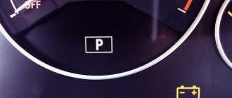
- parking brake condition;
- carburetor choke position;
- emergency pressure in the system;
- battery charge level;
- fuel injection;
- tachometer.
The right turn indicator lamp and resistors are also connected to this group of connectors. In older models before 1995, VAZ 2109, the electrical circuit does not have BSK connectors, so the distribution of lamps is somewhat different and includes some lamps for emergency and control lights, brake fluid level and hazard warning lights.
Lighting fixtures and dimensions
The white connector of the output plugs is connected mainly to sensors that signal the operation of lighting devices, these are lamps:
- outdoor lighting;
- fog lights;
- dimensions;
- emergency lighting;
- high beam;
- turning indicators;
- stops;
- reverse speed headlights;
- heated rear window.
This group of sockets also includes the connection of such indicators as seat belts not fastened and injection toxicity adjustment, indicators for turning left turns on at the moment of starting to move.
Which wire goes where?
First, let's look at the back of the instrument panel. At the top there are:
- fuel level indicator;
- dashboard lighting lamps;
- control of right and left turns (separately);
- tachometer;
- block with many plugs;
- coolant temperature gauge.
As you can see, there is really nothing particularly complicated here. At the bottom of the instrument panel on the back side there are controllers:
- high beam;
- "emergency lights";
- CHECK ENGINE;
- battery charge;
- parking brake;
- oil pressure;
- air damper (for models with a carburetor);
- outdoor lighting work.
Pinout of the dashboard VAZ2108, 2109, 21099
Connection diagram of the instrument cluster before 1996.
1 — relay-interrupter for the parking brake warning lamp; 2 — tachometer with voltage stabilizer; 3 — instrument cluster lighting lamp; 4 — temperature indicator; 5 — BSK control unit; 6 — fuel level indicator; 7 - resistor 50 Ohm, 5 W; 8 — “CHECK ENGINE” control lamp for the toxicity reduction system; 9 — control lamp for high beam headlights; 10 — side light indicator lamp; 11 — backup warning lamp; 12 - warning lamp for unfastened seat belts; 13 — control lamp for left direction indicators; 14 - resistor 470 Ohm, 0.25 W; 15 - electronic voltmeter; 16 — control lamp for right direction indicators; 17 — warning lamp for emergency oil pressure; 18 — fuel reserve warning lamp; 19 — control lamp for the carburetor air damper; 20 — “CHECK ENGINE” warning lamp for the fuel injection system; 21 - parking brake warning lamp.
Instrument cluster wiring diagram after 1996
1 — tachometer; 2 — instrument cluster lighting lamp; 3 — temperature indicator; 4 — BSK control unit; 5 — fuel level indicator; 6 — “CHECK ENGINE” warning lamp for the toxicity reduction system; 7 — control lamp for high beam headlights; 8 — side light indicator lamp; 9 — backup warning lamp; 10 - warning lamp for unfastened seat belts; 11 — control lamp for left direction indicators; 12 — battery charge indicator lamp; 13 — control lamp for right direction indicators; 14 — warning lamp for emergency oil pressure; 15 — fuel reserve warning lamp; 16 — control lamp for the carburetor air damper; 17 — “CHECK ENGINE” warning lamp for the fuel injection system; 18 — parking brake warning lamp; B1 - 91 kOhm resistor; B2 - resistor 50 Ohm, 5 W.
Features of connecting BC
In conclusion, I would like to dwell in more detail on such a point as installing an on-board computer. In the typical pinout diagram shown just above, there is only one wire leading to it - brown. But for the correct operation of this device, this alone will not be enough. Therefore, here is a complete pinout diagram for connecting the on-board computer:
- Green wire – comes from the electronic control unit, needed to obtain information about fuel consumption.
- Orange – goes to the ignition switch, to terminal 15.
- White-red - in the same place, only to terminal 30.
- The common ground wire is black.
- Brown – needed to take speed data.
- Red-green - to the positive circuit of the fuel level sensor.
- White - leads to the light control, which is responsible for the lamps that illuminate the instrument panel.
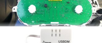
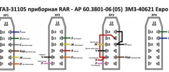
Hello everyone) A new entry is dedicated to the transition from the AutoDevice (AP) panel with one window 2110-3801010-04 to the new VDO Panel 1118-3801010. The devices are completely different, so the modifications affected primarily the pads.
I took a new 32-pin block from the VAZ 2112 harness; I haven’t seen it on sale separately yet.
It’s not possible to get the contacts out of the green block, unlike the old 13-pin ones. Therefore, the wires were cut with a margin. Then they were soldered to the ends of the wires from the white and red blocks, and covered with heat shrink for insulation.
Information that was used during electrical work: Pinout of old-style VAZ 2110 instrument cluster connectors:
Possible faults
The instrument cluster of the VAZ 2115, like any other component of the car, is a device susceptible to various malfunctions.
In this case, there are not so many of them and they are all connected with the electrical part:
- If the instrument panel does not work, there may be several reasons. Either this is poor contact between the device and the ECU, which can be solved by replacing the plug or cleaning the contacts, or a malfunction of the control panel itself, or “glitches” in the operation of the control unit. Typically, the device’s inoperability appears after the PCB has been dismantled and installed in place. In this case, the reason, most likely, is a poor connection of the contacts, so all connectors need to be reconnected, taking into account the pinout.
- Some devices do not work - tachometer, speedometer, fuel level controller. The problem can be either electrical and consist of poor contact, or mechanical (breakage of the speed sensor, fuel level in the gas tank, etc.). Usually replacing the regulators will solve the problem.
- The backlight of the VAZ 2115 instrument panel does not work. If all the bulbs immediately refuse to work, the reason, again, needs to be looked for in the electrical part - maybe a wire has simply come loose somewhere. If only one or several lamps have burned out, then they simply need to be replaced (a video about the installation of a tuned device in a dozen VAZs was made by Pavel Ksenon).
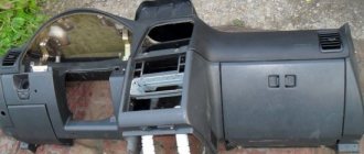
Installation and repair instructions
Replacing the panel, especially if you are installing it on an old VAZ 2112, is a certain difficulty. Older machines do not have some of the functions for which the panel has buttons. The wiring may need to be worked on.
Tools and materials
Standard tools will be required.
But a certain amount of additional materials is needed:
- you will need plugs for extra buttons that are not needed on an old car;
- air duct;
- various inserts, buttons (5 pieces) and pads;
- a new wiring harness suitable for the wiring diagram;
- brackets for mounting the instrument panel;
Algorithm of actions
First you need to remove the old panel. This is done in the same way as on other models of VAZ cars.
When installing, you need to replace the ignition switch with a decimal or Kalinovsky one, depending on how many terminals there are on the block to the lock. You can leave the old one and rearrange the wires, but the new one will work and look better.
The instrument panel wiring needs to be replaced. Also, connect the dimensions with additional two wires in Ш4/13 and Ш3/13 on the mounting block. This applies to older units with 11 relay spaces.
Depending on whether it is an injector or a carburetor, the connection has its own nuances. If you bought a solid factory panel, then instructions should be included with it. Briefly, it can be noted that the injector is not equipped with a speed sensor, please take this into account when installing.
The car's electrical circuit can be of great help. If it is not there, you can find it on the Internet. There are some differences between the VAZ 21124, 2111 and other car variants, so find yours.
If the instrument panel does not work after turning it on, check that the wiring is connected correctly - this is usually the error.
The structure of the instrument console of the VAZ 2115
The standard instrumentation of the VAZ 2115 is the same as on the 2113 and 2114 hatchbacks from the same Samara line. But the sedan body appeared earlier, simultaneously with the VAZ 2110. For the first time, AvtoVAZ began installing panels of a more modern type on cars of that time.
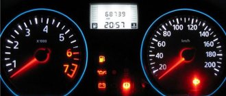
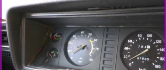
The shield is made according to the model of the manufacturer VDO. Its location is a torpedo, directly behind the steering wheel. It is informative and has 19 elements. Instrument color scheme: red and white light indicators on a black background.
The instrument panel on the VAZ 2115 is conventionally divided into four sectors in width. The left and right extreme parts are scales for coolant temperature and fuel quantity. The most important and voluminous parts of the VAZ 2115 instrument panel are the speedometer and tachometer. The first device shows the speed in kilometers per hour (located to the right). The second is an indicator of the number of crankshaft revolutions per minute (to the left of the center). They are made in the form of scales, the divisions of which are located on a circle.
Directly below the speedometer, the VAZ dashboard has an electronic odometer (mileage indicator). It shows two numbers:
- total vehicle mileage in kilometers;
- mileage from last reference point.
Zeroing is set by the driver using a manual switch, the location of which is under the number 200 on the speedometer. Under the tachometer on the dashboard there is an electronic display with the current time of day, and a button under the “200” indicator of the speedometer allows you to show the temperature outside the window. There are two arrows between the tachometer and speedometer (looking left and right). Each of them flickers green when the corresponding turn signal light is turned on.
The gasoline level scale on the VAZ instrument panel has three main positions. A full tank is designated “1,” and a half-filled tank is designated “1/2.” Next comes the red zone, which indicates a low fuel level. The scale ends with the number “0”. There are three main positions on the coolant level scale: 50, 90 and 130 degrees.
The red zone on the coolant level scale starts at 105 degrees. If the arrow is in this zone, it is necessary to immediately turn off the engine and ensure its normal cooling.
Stages of removing and installing sensors for Lada 2114, the procedure for disassembling and repairing devices for Lada 2113, instructions for assembling the combination of VAZ 2113, VAZ 2115, VAZ 2114. Diagnostics of electrical equipment for Lada 2113. Instructions for repairing electrical equipment, starter, ignition for Lada 2114. Checking instruments, cleaner, lighting Lada 2115
The cars are equipped with an electronic instrument cluster VAZ 2115. It includes a speedometer, a total and daily vehicle mileage meter (odometer) with a liquid crystal display, a tachometer, a fuel level indicator, a coolant temperature indicator, a time and ambient temperature indicator, 12 warning lamps and 6 scale lighting lamps. The car's daily mileage counter can be set to zero using the button located to the right of the indicator. When the ignition is turned off, the daily counter readings do not change, but when the battery is disconnected, its readings are reset. The trip odometer readings are retained when the battery is disconnected. The operation of the devices is controlled by an electronic module, which receives signals from sensors VAZ 2114, VAZ 2115, VAZ 2113. The mechanisms of the temperature and fuel level indicators are of the magnetoelectric type. The tachometer and speedometer needles are driven by stepper motors. The fuel reserve warning lamp is turned on by the electronic module with a resistance of 252 ±2 Ohm on the fuel level sensor, which corresponds to 1/8 of the fuel tank or 5.38 liters of fuel remaining.
Electrical diagram of VAZ 2113, 2114, 2115, Lada Samara 2 (left half): 1 – headlights; 2 – fog lights; 3 – air temperature sensor; 4 – electric motor of the engine cooling system fan; 5 – blocks connected to the wiring harness of the ignition system; 6 – engine compartment lamp switch; 7 – block for connection to a single-wire type audio signal; 8 – sound signal; 9 – washer fluid level sensor; 10 – front brake pad wear sensors; 11 – oil level sensor; 12 – generator; 13 – engine compartment lamp; 14 – coolant temperature indicator sensor; 15 – starter; 16 – battery; 17 – relay for turning on fog lights; 18 – coolant level sensor; 19 – brake fluid level sensor; 20 – reverse light switch; 21 – windshield wiper gearmotor; 22 – oil pressure warning lamp sensor; 23 – block for connecting to the rear window washer electric motor; 24 – electric motor for windshield washer; 25 – instrument cluster; 26 – mounting block. Conventional numbering of plugs in the blocks: A - block headlights; B — electric fuel pump block; C — blocks of the mounting block, ignition switch, windshield wiper gearmotor; D — interior lamp
Addresses of output plugs of the instrument cluster Lada Samara 2. The order of conditional numbering of plugs in the blocks of the VAZ 2114 instrument cluster. The electronic instrument cluster of the VAZ 2113 cannot be repaired, with the exception of replacing indicator lamps and instrument lighting lamps. The components of the instrument cluster are not supplied as spare parts.
Addresses of the output plugs of the instrument cluster
| Plug number | Address (purpose) of the plug |
| White block (X1) | |
| 1 | Housing ("mass") |
| 2 | Low voltage tachometer input |
| 3 | High voltage tachometer input |
| 4 | To fuse F3 of the mounting block (“+” of the battery) |
| 5 | To coolant temperature sensor |
| 6 | To fuse F10 of the mounting block |
| 7 | — |
| 8 | To the motor control controller |
| 9 | To the motor control controller |
| 10 | To fuse F16 (to terminal “15” of the ignition switch) |
| 11 | To the parking brake switch |
| 12 | |
| 13 | To oil pressure warning light sensor |
| Red block (X2) | |
| 1 | To ambient temperature sensor |
| 2 | To fuse F16 (to terminal “15” of the ignition switch) |
| 3 | Housing (weight) |
| 4 | To the instrument lighting control |
| 5 | To turn signal switch (starboard side) |
| 6 | To turn signal switch (left side) |
| 7 | To brake fluid level sensor |
| 8 | To the on-board computer |
| 9 | To speed sensor |
| 10 | To fuel level sensor |
| 11 | To fuse F14 of the mounting block |
| 12 | To hazard warning switch (not used) |
| 13 | To terminal “50” of the ignition switch |