The steering of any vehicle uses many components and parts. One of these important elements is the steering gear. It has been used since the time when the automotive industry was just beginning its path to today's achievements.
The steering gear transmits torque from the steering wheel to the front wheels using a worm gear. The main structural elements are a screw and a gear wheel. Automotive engineers still use this system in most designs.
Diagram and description of the design
The steering gearbox is a separate unit in the steering gear system, the main element of which is the worm shaft. It increases the force applied by the driver to the steered wheels when the steering wheel is rotated.
Typical diagram of a Niva Chevrolet steering gear:
This part has the original serial number: 2123-3400010-20.
The mechanism is put on the market assembled with a bipod in a branded white and blue cardboard package with a quality certificate and an annual guarantee.
The Chevrolet Niva uses a mechanism in which a globoid-type worm (variable shaft diameter) is installed. This design ensures reliable vehicle control at any speed and on different road surfaces.
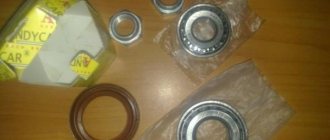
In the steering system gearbox, the worm shaft rests on 2 rolling bearings, the same number of bearings support the rotation of the bipod shaft. Ball bearings serve to reduce friction of the main parts, also making it easier to turn the steering wheel in different directions.
When the steering wheel rotates, torque is transmitted from the steering column shafts to a worm unit, which is engaged with a roller located on the bipod shaft.
Reference! The gear ratio is 16.4.
The bipod connects the steering linkage system through articulated pins. The transmission of movement from the middle rod to the right side rod occurs through a pendulum lever.
The worm steering mechanism used on off-road vehicles is quite shock-resistant. It easily absorbs all vibrations and irregularities from the road surface
Due to the simplicity of its design, it has a high degree of wear resistance, providing the VAZ 2123 with good maneuverability under different road conditions and at any speed.
Useful!
The minor disadvantages of this mechanism include the complexity of manufacturing. Also, due to the large number of moving and rubbing elements, the worm gear must be tightened at certain intervals.
During vehicle operation, moving elements wear out in the worm gear over time and the technological gap increases. As a result, extraneous sounds appear. The first signs of an adjustment violation are a beating and a significant increase in the free play of the steering wheel, and the clarity of vehicle control is lost.
All this directly proportionally affects the safety of driving this car. If you do not adjust and tighten this play of the main pair in time, then due to the resulting runout, scuffs begin to form on the metal of the worm and bipod and the drive completely fails.
Important! Steering is one of the main vehicle systems responsible for safety. Therefore, operating a car with a faulty steering system is prohibited by the Road Traffic Regulations.
Common problems with the steering of Niva and Chevrolet Niva and options for dealing with them
The occurrence of problems in the steering, as a rule, is associated with wear of structural elements in the connections of parts. In this case, characteristic backlashes appear. If the rubber seals are subject to deformation, then during operation sounds from the contact of metal parts are heard.
First of all, when operating a car, the anthers and protective covers are destroyed, preventing dirt and water from entering the joints of the steering control elements. If the rubber boots are damaged, they must be replaced immediately. This way you can have time to preserve the functionality of the part itself.
If certain malfunctions occur, they can be eliminated by making appropriate adjustments:
- adjusting the worm and roller clearance (incorrect clearance can cause noise, increased play when turning the steering wheel, or too tight rotation);
- tightening the ball pin nuts in the steering rods (loosening the nuts also causes an increase in play and also leads to angular vibrations of the wheels);
- adjusting the nut of the pendulum arm axis (noise, tight steering wheel rotation, increased play);
- incorrect alignment of wheel angles (the car pulls to the side).
In case of deformation and violation of the geometric characteristics of parts, as well as their mechanical wear, replacement is necessary. For me, replacing the entire steering linkage, taking into account the price of spare parts, costs only 2,600 rubles, and is done within 1.5 hours. Also, any steering element can be replaced in the shortest possible time at a cost lower than at most service stations in the city.
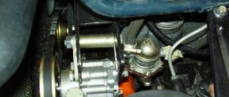
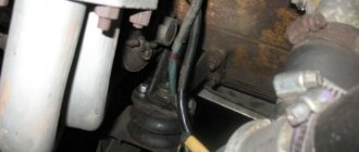
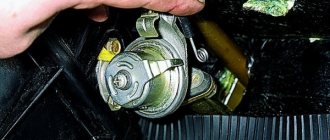
The power steering pump is mounted on a bracket on the left side of the engine.
Replacing the power steering gear oil seal
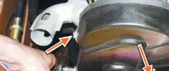
The safety of the Chevrolet Niva steering system is ensured by folding the steering shaft due to universal joints and special fastening of the steering shaft bracket. Niva models were not equipped with an amplifier.
% discount on spare parts and accessories for foreign cars in Academy Plus stores.
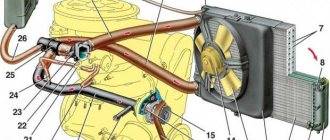
Power steering Chevrolet Niva 1 - power steering pump; 2 - sealing washer; 3 — bolt fitting; 4 — high pressure hose; 5 — pump supply hose; 6 — power steering radiator Chevy Niva; 7 — hose for draining fluid from the radiator; 8 — tank cover; 9 — tank; 10 - clamp; 11 — hose for supplying fluid to the radiator; 12 - steering mechanism The Chevrolet Niva steering shaft is a two-link shaft, consisting of an upper steering shaft and an intermediate one.
Do-it-yourself removal, installation and repair
To repair or replace a switchgear element, it is necessary to dismantle the worm assembly.
You will need:
- locksmith's key to "17";
- tool set 1/2 with ratchet and sockets;
- slotted screwdriver.
- portable lamp to illuminate the repair area.
Dismantling sequence:
- Place the Niva on a lift or inspection ditch. To ensure safety, we use wheel chocks.
- Remove all working fluid from the system.
- Unscrew the fastening bolt of the lower end of the universal joint.
- Jack up the front part of the car and remove the left wheel.
- We remove the hinge joints of the middle and side rods from the mounting holes of the bipod. For the convenience of further work, we recommend moving the side rod to the side.
- Using the head at “19” we unscrew the high pressure hose.
- Remove the sealing copper washers.
- Using a socket set to “22”, unscrew the bolt-fitting of the tip of the fluid supply hose to the radiator.
- Next, loosen the nuts of the bolts securing the steering gear housing to the spar. Remove all mounting bolts.
- Carefully remove the thrust washers that are located between the steering gear housing and the left side member of the vehicle body. When reassembling in reverse order, be sure to put them back in place.
- After this, you should remove and unfasten the middle thrust ball pin from the bipod.
- Remove the steering gear.
- Assembling the steering mechanism should be done in the reverse order. Without fully tightening the fasteners, check that the entire system is working and that there are no distortions.
- Required tightening torques for steering gear nuts:
- worm gear housing mounting nut: 33.3-41.2 Nm;
- steering link ball pin nut: 42.1-63 Nm;
- bipod nut: 199.9-247 Nm.
After assembling all the parts and tightening the fasteners, it is necessary to bleed the power steering.
Note! Before tightening the worm gear housing mounting bolts, adjust the position of the steering gear so that the angle “a” indicated in the figure below is 28°.
The worm drive oil seal is installed in the steering gear cover itself on the passenger compartment side of the car. When servicing and repairing the drive unit with your own hands, you must:
- Replace all O-ring seals of the support bearings in the housing.
- replace the worm seal.
The oil seal has dimensions: 20*30*7 mm. The selection of a new oil seal must be done in an auto shop according to the old model.
Replacing power steering Lada 2131 (VAZ 2131)
Installation of the steering gearbox on NIVU
The lack of power steering is somehow very outdated. Especially in the future the installation of wheels of non-standard size. Therefore, immediately after purchasing the car, it was decided to install power steering. I did not consider the EUR because my steering gearbox (hereinafter referred to as RR) was leaking oil and was very loose, in general, it had to be replaced.
The next day I bought a RR, power steering pump from a Mitsubishi Galant (80s)
Galant pump
That same day in the evening I came across an article on the Internet about installing such a RR in 2121, which contains a template for cutting a hole in the engine shield for this RR (since it is slightly larger than the original one). The template, by the way, is not life-size, so I had to draw it again.
sample
Since I work in an advertising agency, I printed a template on self-adhesive film and stuck it on the engine shield.
Template on film
I cut it out using a small grinder and a drill. Use discs with a thickness of 0.8 or 1 mm, although they wear off faster than thick ones, they are a pleasure to cut; they cut very quickly.
Manufacturing a power steering pump bracket and installing an adjustable steering column from 2110 at NIVU
I bought the missing items:
1. Power steering belt 21214
2. Power steering pulley for crankshaft (includes ratchet nut and spacer washer
3. Plastic tank for power steering gas 31105.
4. High pressure hose (fortunately the hose fits both the rail and the pump, although it’s a bit long, but I didn’t have to choose.
5. 2 liters of power steering oil (there is about a liter in the system, but I spilled half of one can while I was experimenting with the steering).
I started by installing the pulley. I did not use a spacer washer, since with it the power steering pulley moves very far away from the main pulley. I don’t know whether this is how it should be, or whether in 21214 the main pulley has a different shape. In general, I threw out the washer, but the nut had to be modified, or rather, it had to cut the thread in it to the end, shorten it (to the width of the washer) and grind off the chamfer that should fit into the washer.
Next is the bracket for attaching the power steering pump to the engine block. I won’t describe this, because I doubt that anyone will, like me, install a power steering pump from a Galant. I'll just attach a few photos.
The bracket was made from a plate 5 mm thick.
It needed to be painted with something, but the cans were all practically empty. in the end it turned out like this.
I installed it, connected all the hoses, filled it with fluid, and turned the steering wheel. The liquid has leaked. I poured more. I started it up and a fountain of 50 centimeters came out of the tank (an unpumped system leads to this result). I added more fluid and thoroughly bled the entire system. Started it up...and HURRAY! everything is working! True, there are still some movements in the tank, in my opinion, this should not be the case, this is not the case in the UAZ.
Guide to installing power steering on NIVA type vehicles and its modifications
This manual describes the installation sequence of the power steering, the requirements for its installation and filling with hydraulic fluid, for vehicles such as VAZ-21213, 21214, 2131 and their modifications, with injection and carburetor engines.
1. General requirements
Before starting installation work, check the power steering installation kit in accordance with the attached list. After installation, hydraulic system hoses must be routed freely and with small bends (with as large bend radii as possible). Sealing copper washers must be soft, i.e. in an annealed state; if necessary, additional annealing must be done by heating. Before starting work, place the car on a horizontal, level area and brake with the parking brake and additional blocks under the wheels.
2. Preparing the car for installation of the hydraulic booster - removing the car components 2.1. Having opened the hood, remove the negative terminal from the battery (tool: wrench 10) 2.2. Remove the spare wheel and spare wheel mounting bracket (tool; socket wrench 13, socket wrench 10) 2.3. Remove the windshield washer reservoir by disconnecting the tubes and wires from the electric washer motors 2.4. For a car with an injection engine, remove the fuel filter on the left mudguard of the car by unscrewing the nuts securing it and moving it to the side without disconnecting the fuel lines (tool: socket wrench 10) 2.5. Remove the upper and lower steering shaft casings by unscrewing the fastening screws (tool: Phillips screwdriver) 2.6. Remove the wiring harness connectors from the ignition switch, from the hazard warning switch, from the three-lever switch, from the brake light switch 2.7. Unscrew the bolt securing the lower end of the intermediate steering wheel driveshaft (tool: socket wrench 13, wrench 13) 2.8. Remove the steering shaft bracket with the steering wheel and intermediate propeller shaft by unscrewing two nuts and two bolts securing it (socket wrench 13 with extension, chisel, hammer) 2.9. Remove the intermediate steering driveshaft. unscrewing the bolt securing its upper end (tool: socket wrench 13. wrench 13) 2.10. Remove the brake booster rod by removing the mounting bracket (tool: flat-head screwdriver, pliers) 2.11. Remove the master brake cylinder from the vacuum booster by unscrewing the nuts securing it and moving it up and to the side without disconnecting the brake pipes (tool: spanner 17) 2.12. Remove the vacuum brake booster by unscrewing the four nuts securing it (tool: socket wrench 13 with extension) 2.13. Remove the clutch drive cylinder and its expansion tank by unscrewing the two nuts securing it and moving it to the side without disconnecting the supply hose from the tank (tool: socket wrench 13 with extension, socket wrench 10 with extension) 2.14. Remove the pedal mounting bracket 2.15. Press the ball pins of the middle and left tie rods out of the holes in the steering gear bipod. why unscrew and unscrew the nuts securing the rods (tools: pliers, socket wrench 22 with extension, puller) 2.16. Remove the steering mechanism with the bipod by unscrewing the nuts and removing the bots that secure it to the spar (tool: socket wrench 17 with extension, socket wrench 17) 2.17. Unscrew the nut securing the bipod of the steering mechanism, having first straightened the lock washer, and remove the bipod from the steering mechanism shaft with a puller, securing the mechanism body in a vice through spacers (tool: vice, socket wrench 30 with extension, puller) 2.18. For a car with an injection engine, remove the ignition module with the bracket assembly by disconnecting the high voltage wires and the wiring harness block, and unscrewing the bracket fastening nuts (tool: socket wrench 13 with extension) 2.19. For a car with an injection engine, remove the adsorber with bracket assembly from the left mudguard by unscrewing the nuts securing the bracket (tool: socket wrench 10) 2.20. Unscrew the upper left M6 stud securing the timing cover from the front of the cylinder block, having first unscrewed the nut (tool: socket wrench 10, wrench 10) 2.21. Unscrew the M8x45 bolt securing the cylinder head from the front left (tool; socket wrench 13 with extension)
3. Modification of the body for installation of hydraulic booster 3.1. Enlarge the hole in the bulkhead by cutting using the supplied full-size hole outline template in FIG. 1. Sharp edges and burrs should be dulled after cutting (tool: template according to fig. 1. electric drill, D9 mm drill, jigsaw, chisel, hammer, flat file)
Note. In this article, clicking on the pictures opens their full-size versions in new windows.
3.2. Make a groove in the pedal block bracket, marking it according to the sketch shown in FIGURE 2, blunt the sharp edges and burrs after cutting (tool: caliper, electric circular saw, flat file)
3.3. Touch up the primer along the contour of the edge of the hole in the front panel and the groove on the pedal unit mounting bracket (tool: brush, automotive primer)
4. Modification of the engine to install a power steering pump 4.1. Mark the center of the side hole on the cylinder block according to FIGURE. 3, installing the power steering pump mounting bracket on the block and securing it with the cylinder head mounting bolt M8x45x1.25 and the M6x25 bolt included in the kit. After marking the center, remove the bracket. unscrewing the previously installed bolts: (tool socket wrench 13, socket wrench 17, hammer, punch)
4.2. Make a threaded hole M8x1.25 with a depth of 12 mm in the cylinder block at the intended center, in accordance with the sketch according to FIGURE 3. Remove chips (tool: electric drill, drill D6.5, tap M8x1.25, tap handle) 4.3. For a car with an injection engine - Make a threaded hole M8x 1.25 with a depth of 12 mm in the boss of the cylinder flare, located in the center left at the top of the block, in accordance with the pattern according to FIGURE 4. Remove chips (tool: hammer, electric drill punch, drill D6.5; tap M8x1.25; tap handle)
4.4. Unscrew the nut securing the engine crankshaft pulley, engaging 4th gear in the gearbox and the handbrake (tool: socket wrench 38, wrench) 4.5. For a car with an injection engine - Modify the ignition module bracket. having first unscrewed the coil block from the bracket, and then unbent and straightened its eye according to FIGURE 4 (tool: socket wrench 10, bench vice, hammer)
5. Installing the bipod on the hydraulic booster 5.1. Cut off the front stop on the steering bipod by 3...5 mm according to the sketch in FIGURE 5 (tool: electric circular saw) 5.2. Install the modified steering bipod onto the lower shaft of the power steering bipod. aligning the double tooth of the spline hole of the bipod with a mark in the form of a mark on the end of the hydraulic booster bipod shaft.
5.3. Install the lock washer and tighten the bipod fastening nut to a torque of 140… 160 Nm. Lock the nut by bending the arms of the lock washer (14...16 kgm) (tools: socket head 32, torque wrench, chisel, hammer)
6. Installation of the hydraulic booster with bipod assembly 6.1 Set the average position of the steering shaft of the hydraulic booster relative to its extreme positions by rotating the shaft, while the mark on the end of the steering shaft of the hydraulic booster should coincide with the mark on its body. 6.2. Install the hydraulic booster onto the body side member and secure it with three bolts and self-locking nuts from the kit. Tighten the nuts of the hydraulic booster mounting bolts to a torque of 35…45 Nm (3.5…4.5 kgf) (tool: socket wrench 17, socket head 17, torque wrench; 6.3. Seal the junction of the hydraulic booster housing and the car body using polyurethane foam or silicone. 6.4. Install ball pins steering rods into the conical holes of the steering bipod, tighten with castle nuts to a torque of 45...55 Nm (4.5...5.5 kgm), cotter (tool: socket head 22, torque wrench, pliers) 7. Installation of the power steering pump and its drive 7.1. Install the pump drive pulley and the spacer bushing from the kit, secure them with a special extended nut with a torque of 110...120 Nm (11...12 kGm). In this case, the pump drive pulley and bushing are centered on the nut (tool: socket head 38, torque wrench) 7.2. Install the power steering pump bracket according to Fig. 3, install and tighten the bolts with locking washers from the kit M6x25 bolt -6...8 Nm (0.6...0.8 kgf); M8x20 bolt -20...25 Nm (2...2.5 kgf). Using an M8x50 bolt, secure the cylinder head through the upper support pad of the bracket, placing a flat spacer washer 2 mm thick under it and tightening the bolt to a torque of 35... 38 Nm (3.5...3.8 kgm) (tool: socket wrench 10, socket wrench 13 with extension) 7.3 . Install the power steering pump on the fixed bracket according to FIGURE 3, without tightening the two M12x1.75x30 bolts securing the pump with flat washers. 7.4. Place the V-belt from the kit onto the pump drive pulley on the crankshaft and onto the pulley of the pump itself. Tension the belt by moving the pump in the grooves of the bracket and tighten the pump mounting bolts to a torque of 20...23 Nm (2...2.3 kgm). The deflection of the upper branch of the pump drive belt in the middle part should be 8. . 12 mm when exposed to a force of 100 N (10 kg), if necessary, tighten the belt (tools: socket head 17. torque wrench, dynamometer, ruler, caliper)
8. Installation of hydraulic hoses 8.1. Remove the transport plugs from the holes of the power steering, pump, power steering reservoir and hoses immediately before installing the hoses, while ensuring that dirt cannot get into the components and assemblies (tool: Phillips screwdriver) 8.2. Install a high-pressure hose, connecting it with one end to the supply hole of the pump, and the other end to the high-pressure hole of the hydraulic booster through a hollow bolt M14x 1.5 and two copper gaskets D14 mm. Tighten the connections hermetically to a torque of 37…40 Nm (3.7…4 kgm) (tool: socket wrench 17 with extension, wrench 13) 8.3. After tightening the M14x1.5 hollow bolts, make a final tightening of the nuts of the hose corner threaded ends, making sure that the hose does not bend or touch the car parts (tool: wrench 19, wrench 17) 8.4. Install the low pressure pipe D12 from the kit onto the drain hole of the hydraulic booster through a hollow bolt M16×1.5 and two copper gaskets D16. Turn the installed pipe on the hydraulic booster so that the hose with the clamp is put on. Tighten the connection hermetically to a torque of 37…40 Nm (3.7…4 kgm) (tool: socket wrench 19 with extension) 8.5. Install the low pressure drain hose D12 onto the low pressure pipe D12 on the hydraulic booster. Tighten the hose with the screw clamp from the kit to a torque of 2Km (0.2kGm) (tool: socket wrench 6) 8.6. Install the low pressure supply hose D16 onto the inlet pump pipe. Tighten the hose with the screw clamp from the kit to a torque of 2 Nm (0.2 kgm) (tool: flat-head screwdriver, socket wrench 6)
9. Installed previously removed components and assemblies and final assembly of power steering systems 9.1. Install and secure the modified pedal unit mounting bracket in the reverse order of removal. 9.2. Install and secure the clutch cylinder, brake master cylinder and brake booster in the reverse order of removal. 9.3. Install the bracket for fastening the power steering oil reservoir so that the center of the circle of the bracket clamp is located between the main brake cylinder and the side member according to FIGURE 6, and secure the bracket with two self-tapping screws, having previously drilled two holes with a diameter of 3 mm on the amplifier of the front panel of the body (tool: electric drill, center punch , drill DZ mm, Phillips screwdriver) 9 4. Install the power steering reservoir so that the reservoir pipes are located parallel to the axis of the main brake cylinder, and tighten the bracket clamp with an M6x25 bolt to a torque of 4 Nm (0.4 kgm) (tool; socket wrench 10) 9.5. Connect the low-pressure drain hose D12 coming from the power steering to the pipe D12 of the power steering reservoir. Tighten the hose with the screw clamp from the kit to a torque of 2 Nm (0.2 kgm), if necessary, adjust the length of the hose to the location (tool: flat-head screwdriver, wrench 6) 9.6. Connect the low pressure supply hose D16 coming from the pump to the pipe D16 of the power steering reservoir. Tighten the hose with the screw clamp from the kit to a torque of 2 Nm (0.2 kgm), if necessary, adjust the length of the hose to the location (tool: flat-head screwdriver, wrench 6) 9.7. Install the intermediate steering propeller shaft from the kit on the steering shaft of the previously removed steering shaft bracket, and tighten the locking bolt with nut and locking washer to a torque of 30…33 Nm (3…3.3 kgm). Attention - the fork locking bolt must pass through the annular groove of the spline shaft (tool: socket head 13, wrench 13, torque wrench) 9.8. Install and secure, without tightening, the steering shaft bracket with the steering wheel using the bolts and locking washers from the kit, replacing the breakaway bolts. At the same time, turn the steering wheel shaft so that the steering wheel spokes are horizontal. It is necessary to ensure that the average position of the power steering shaft is maintained relative to its extreme positions, and that the mark on the end of the power steering shaft matches the mark on its housing. In this position, connect the lower fork of the intermediate propeller steering shaft to the power steering shaft. Tighten the locking bolt with nut and lock washer to a torque of 30…33 Nm (3…3.3 kgm). Attention - the fork locking bolt must pass through the annular groove of the spline shaft (tool; socket wrench 10. socket wrench 13 with extension, wrench 13. torque wrench) 9.9. Install the steering wheel with the steering column and bracket in the axial direction so that there is a gap of 2...3 mm between the plastic thrust washer and the column bearing housing. Tighten the M8 nuts for fastening the bracket to a torque of 27...30 Nm (2.7...3 kGm), tighten the M6 bolts for fastening the bracket to a torque of 7...8 Nm (0.7...0.8 kgm) of the shaft. If necessary, cut the rubber floor mat as follows. so that it does not touch the rotating parts of the intermediate steering propeller shaft (tool: socket socket 10 with extension, socket socket 13 with extension, torque wrench, shoemaker's knife) 9.10. Place the wiring harness blocks on the ignition switch, on the hazard warning switch, on the three-lever switch, to the brake light switch 9.11. Install the upper and lower steering shaft housings by tightening the fastening screws (tool: Phillips screwdriver) 9.12. For a car with an injection engine, install the adsorber with the bracket assembly in the lower part of the left mudguard in place like this. so that it does not touch the pulleys on the engine crankshaft. Drill holes with a diameter of 6.5 mm in place. Secure the adsorber with M6x20 bolts from the kit and bracket fastening nuts with washers (tools: socket head 10, socket wrench 10, electric drill, drill D6.5 mm) 9.13. Modify the windshield washer reservoir in the lower corner on the engine side by first draining the liquid from it. To modify it, you need to heat the corner of the tank with warm air from a hairdryer and, by pressing with a wooden block, deform the corner inside the tank. Try on the reservoir, installing it in place; the corner of the reservoir should not touch the power steering pump pulley. If necessary, repeat the modification (tool: electric hair dryer, wooden block) 9.14. Install the modified windshield washer reservoir by connecting the tubes and wires to the washer motors. 9.15. For a car with an injection engine, install the fuel filter on the left mudguard of the car, tighten the nuts securing it (tool: socket wrench 10) 9.16. For a car with an injection engine - install the ignition module with the bracket assembly, as shown in FIGURE 4, and screw the M8x16 bolt with the lock washer from the kit into the threaded hole previously made in the cylinder block, tighten the bolt to a torque of 25...30 Nm (2.5 ...3 kgm). Connect the high voltage wires and the wiring harness block. If necessary, retie the wiring harness (tool: socket wrench 13 with extension)
10. Filling the power steering hydraulic system with oil 10.1. Attention - it is prohibited to start the engine without oil in the power steering hydraulic system to avoid damage to the power steering pump. 10.2. Unscrew the power steering reservoir cap and add oil to the bottom edge of the reservoir filler neck. For refueling, use ATF oil in accordance with the attached list of recommended oils. The volume of oil for refilling the hydraulic booster system is 1 liter 10.3 Place the front wheels of the car on a jack or lift, having previously braked the rear wheels with a hand brake and pads 10.4. Turn the car wheels from lock to lock several times. adding oil to the tank 10.5. If necessary, remove the remaining air from the power steering system by unscrewing the special fitting on the power steering with a wrench. After draining the liquid with bubbles, tighten the fitting (tool: spanner 10.6. If necessary, repeat the bleeding operation, adding liquid and turning the wheels from stop to stop until liquid flows out of the fitting without bubbles 10.7. Bring the oil level in the tank to the MAX mark dipstick of the tank cap, adding oil. Tighten the tank cap tightly 10.8. Lower the front wheels of the car, put the minus terminal on the battery and tighten it with a bolt (tool: wrench 10) 10.9. Start the engine and check the operation of the hydraulic booster, make sure there are no leaks from system when turning the wheels to their extreme positions, If necessary, eliminate the identified leaks and repeat the procedure for filling and bleeding the hydraulic booster 10.10. Install the spare wheel mounting bracket and the spare wheel (tool: socket wrench 13. socket wrench 10). Close the hood of the car.
11. Recommended brands of oils for filling the power steering Attention: fill the power steering only with oils for automatic transmissions. AGIP DEXRON II D-21103 ARAL OEL RZ19 DEXRON D-20383 AVIA FLUID ATF 77 DEXRON D-20760 BP AUTRAN DX II D-20335 CALTEX TEXAMATIC FLUID DEXRON D-20139 CASTROL TQ DEXRON II D-20815 ESSO ATF DEXRON D-21 065 ESSO ATF DEXRON D-21611 SHELL DEXRON II D-20137 TEXACO TEXAMATIC 9226 D-20112 VEEDOL ATF DEXRON II D-20816 PENTOSIN CHF IIS
Installing power steering from a Chevrolet Niva to the standard location of the Niva generator
Finally, I collected all the missing parts and installed the power steering from the Chevrolet Niva. The fact that the steering wheel has become easier to turn is an understatement! Now I don't know how I drove before. Today I took it for a test drive - everything was fine. Now, even with the rear lock on, the steering wheel can be turned with your finger.
I installed the power steering pump in the regular place of the generator. Since my tractor has long taken root at the top. Well, now the nuances that I encountered.
Purchased the pump, steering gear, reservoir and pump bracket
1) I had to make the pump bracket myself. 2) I purchased a pulley from GUR 21214 with a nut and spacer. 3) I selected the belt, length 670mm 4) I cut a hole for the steering gear according to the template. I foamed the excess, I didn’t have anther. 5) I trimmed the bipod so that the bolt would not interfere with full rotation of the steering wheel. 6) I ordered a high-pressure hose, it was done in 10 minutes. Length 1.1 meters. Goes under engine protection. The ends are 90 degrees. 7) Low pressure hoses Cardan between the steering wheel and the steering wheel. The car came from 21214 Niva with an electric booster, it came without any modifications.
Mounting plates for power steering pump in NIVU
Many people buy a power steering kit from Niva Chevrolet (2123). To install the pump to the power steering bracket, you need these plates; I have never seen them on sale anywhere. Made my own. Completely repeat the factory ones.
Plates securing the power steering pump to the bracket.
I made it with reserve.
GUR NIVA bracket - working on mistakes
I once noticed that when the internal combustion engine is running at idle, the generator along with the bracket moves suspiciously. I turned it off, tugged at the gene, the bracket, the power steering pump, everything sits dead. I start the engine again - no change. I decided to tighten the fastening of the bracket and then everything immediately fell into place, as soon as I touched the bolt with a key, half a bolt breaks off, I touch the next one, the same crap + the same thing happens with the belt tensioner bracket on the gene. Naturally, the broken pieces remain in the block. I started to take it apart.
You can see a break in the cylinder head and block
I removed the radiator because I thought I would have to drill out the broken pieces, but to my surprise, even when they broke by the face, they were unscrewed by hand.
Next, after removing the bracket, I began to find out the cause of this breakdown. Upon closer examination of all the details, it turned out that the original mounting studs for the front cover of the internal combustion engine (which I replaced with longer bolts when installing the bracket) were 6, the holes in the bracket were 8. Well, the material from which they were made played an important role these bolts. To do this, we order adapter pins M6-M8 of the appropriate length from the turner. He turned them out of a drill rod, in short, you'll break the hell out of them.
Left: adapter studs from drill rod. right: original factory stud
We install the bracket on new studs. And in order not to remember this trouble anymore, I decided to secure the bracket with another point that was provided, but was not secured there because... When installing the power steering, I was afraid to drill the block. This point is in the distributor area, here it is:
Drilled, tapped and screwed in the bolt.
Now the bracket, as it should be, is fixed at all 4 points.
I put everything back in place, started it up, checked it - everything is fine. I hope it lasts for a long time
https://www.niva-faq.msk.ru/tehnika/rulevoe/igur.htm, https://www.drive2.ru/l/1660949/, https://www.drive2.ru/l/1712351 /, https://www.drive2.ru/l/5100674/, https://www.drive2.ru/l/6352414/, https://www.drive2.ru/l/4230093/
Source
- https://spike.su/index.php/GUR-NIVA.html
Maintenance and adjustment of the worm unit
Like any other component, the steering gear requires regular maintenance. Our recommendations will help you avoid large costs for repair work and premature replacement of the unit:
- A seasonal visual inspection allows you to timely detect oil leaks through seals and oil seals, mechanical microcracks and other operational defects of the gearbox frame.
- Timely adjustment of the drive worm clearance will help to avoid increased runout of the entire mechanism, increased noise levels during rotation, and avoid the appearance of a “stiff steering wheel” effect.
- Regular monitoring of the required oil level in the worm gear housing and compliance with oil change intervals based on mileage.
The basic steering gearbox is equipped with a worm pair, in which mechanical friction between the worm and the worm gear occurs during operation.
Reference!
To extend the trouble-free operation life of the unit, it is necessary to use only high-quality lubricant in the gearbox and monitor the condition of the working surfaces.
Adjustment
After the procedure of repairing or replacing the steering worm drive, it is necessary to make adjustment settings.
Checking the steering wheel play must be done on a flat horizontal platform with the required pressure in the car tires. The play, measured by the free play of the steering rim, should be within 5°.
How to set up optimal performance:
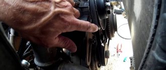
- We open the hood and find the unit we need on the left side of the engine compartment (as the vehicle moves). An adjusting screw and a lock nut are installed on the top of the gearbox cover.
- Loosen the lock nut. Using a slotted screwdriver, rotate the adjusting screw clockwise, and the control backlash should decrease.
If the screw is no longer long enough for adjustment, the unit must be replaced.
Important!
Correct and timely maintenance of the steering gear is the key to long-term trouble-free operation in any conditions.
Servicing the Niva steering gear (Chevrolet, 2121, 21213 and 21214)
Like any other component, the steering gear should be maintained by adhering to three simple rules.
Three simple, but at the same time important rules that should always be followed:
- Timely visual inspection.
- Timely control of the oil level in the gearbox.
- Timely adjustment.
Timely visual inspection allows you to quickly identify and detect oil leaks, mechanical defects and other damage to the gearbox housing.
Oil level monitoring – this also includes timely oil changes.
Some craftsmen got the hang of pouring liquid LITOL into the gearbox, having previously melted it on a tile in a vessel.
Good or bad? Everyone decides for themselves. My personal opinion is that this measure takes place in the maintenance of gearboxes whose operational life is approaching sunset. The gaps in the gears can no longer be eliminated by simple adjustment, and the only way out, in order to get rid of the knocking, is to pour liquid lithol into the gearbox housing, thereby leveling the backlash at least a little.
Well, the adjustment allows you to eliminate play in the gearbox gears in a timely manner.
Consistently following the three recommendations above, rest assured that the steering gear in the field will serve you faithfully for more than tens of thousands of kilometers.
Repair and assembly
Correct and timely maintenance of the steering gear is the key to long-lasting and reliable operation, but there are times when breakdowns do occur. In this case, repairs with complete or partial disassembly simply cannot be avoided. When repairing, it is necessary to pay attention to some features and important points, the use of which will increase the reliability of the mechanism and improve its characteristics.
Steering gear repair
To remove and disassemble the gearbox, it is necessary to hang the front of the car and remove the steering rods. From inside, unscrew the bolt securing the supply shaft from the gearbox shaft. Next, we disconnect the gearbox from the spar by unscrewing the three bolts with spanners. In the engine compartment, remove the hoses and parts that are located in the line of the steering rods.
When the gearbox is unscrewed and removed from the shaft in the cabin, we pull it out of the engine compartment by turning the bipod to the left. Particular attention should be paid to the condition of the gaskets, their location and degree of wear. An unreliable seal can lead to loss of lubrication or contamination of internal cavities. The next step is to unscrew the plug and remove the oil from the steering gear housing, after which you need to unscrew the bipod.
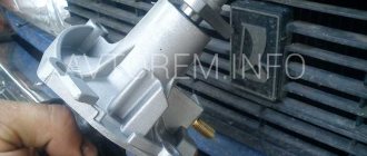
We place the gearbox on a stand made of two boards so as not to damage the shaft splines and unscrew the nut, then remove the bipod. Additionally, you can screw the nut onto the shaft until the ends are mutually aligned. Next, disconnect the steering gear cover by gradually unscrewing the locknut of the adjusting bolt and remove the cover, gradually moving it towards the worm.
In this case, you need to be especially careful with the gaskets if they are in good condition; at the slightest jam or pressing out, the gasket must be replaced. The next step is to remove the bipod shaft, press in the worm shaft and remove the seals. All cavities must be washed and wiped with a rag, checking for dents, chips and any other damage. It is also necessary to check the crankcase for the presence of metal shavings, which indicates wear of certain parts. It is imperative to check the gaps and play in the mating parts and check the wear of the working surfaces. After carrying out a defective inspection of the steering gear, we replace damaged parts if necessary.
We carry out assembly in the reverse order, making sure to lubricate the parts with oil, and all oil seals with grease (lithol). Install a new cover gasket with an adjusting screw. We mount the bipod, tightening the nut as much as possible. Then we install the steering gear in its regular place, special attention must be paid to the connection of the worm with the intermediate shaft; distortions and misalignments are not allowed here.
It is also necessary to align the direction of the bipod and the steering wheel. The average position of the bipod can be determined by counting the number of shaft revolutions and dividing by two. Next, tighten the gearbox mounting nuts (it is advisable to install new ones), attach the steering rods to the bipod. Fill the gear housing with oil and use the adjusting bolt to select the play in the steering gear. In order to avoid damage to wheel tires and loss of controllability of the VAZ 2121 car, it is necessary to diagnose the camber (toe) on a stand.